Color Sensor TCS34725 library
This is a 6 pin chip with filtered sensors for red, green, blue and white light, it has a huge dynamic range.
This library includes all the functionality of the chip and the library do not include delays to wait for conversions, there are other ways to handle that. My initial plan was to use the Adafruit library, but I had trouble with use non-I2C pins and it included a lot of delays, not what I want.
Contents
Color Sensor TCS34725 library
The sensor and module
Requirements
The library functions
Includes
Constants
Structures
RGBC
LightValues
All functions
Constructor
Integration time
Wait time
Gain setting
Starting and stopping conversion
Interrupt value configuration
Interrupts
Conversion ready
Reading values
Advanced functions
Miscellaneous
Examples
Reading sensor at any time
Reading after a conversion
Using interrupt
Using interrupt pin, but not interrupt
Detecting colors
Estimating lux and color temperature (CT)
My test setup
Conclusion
Notes and download
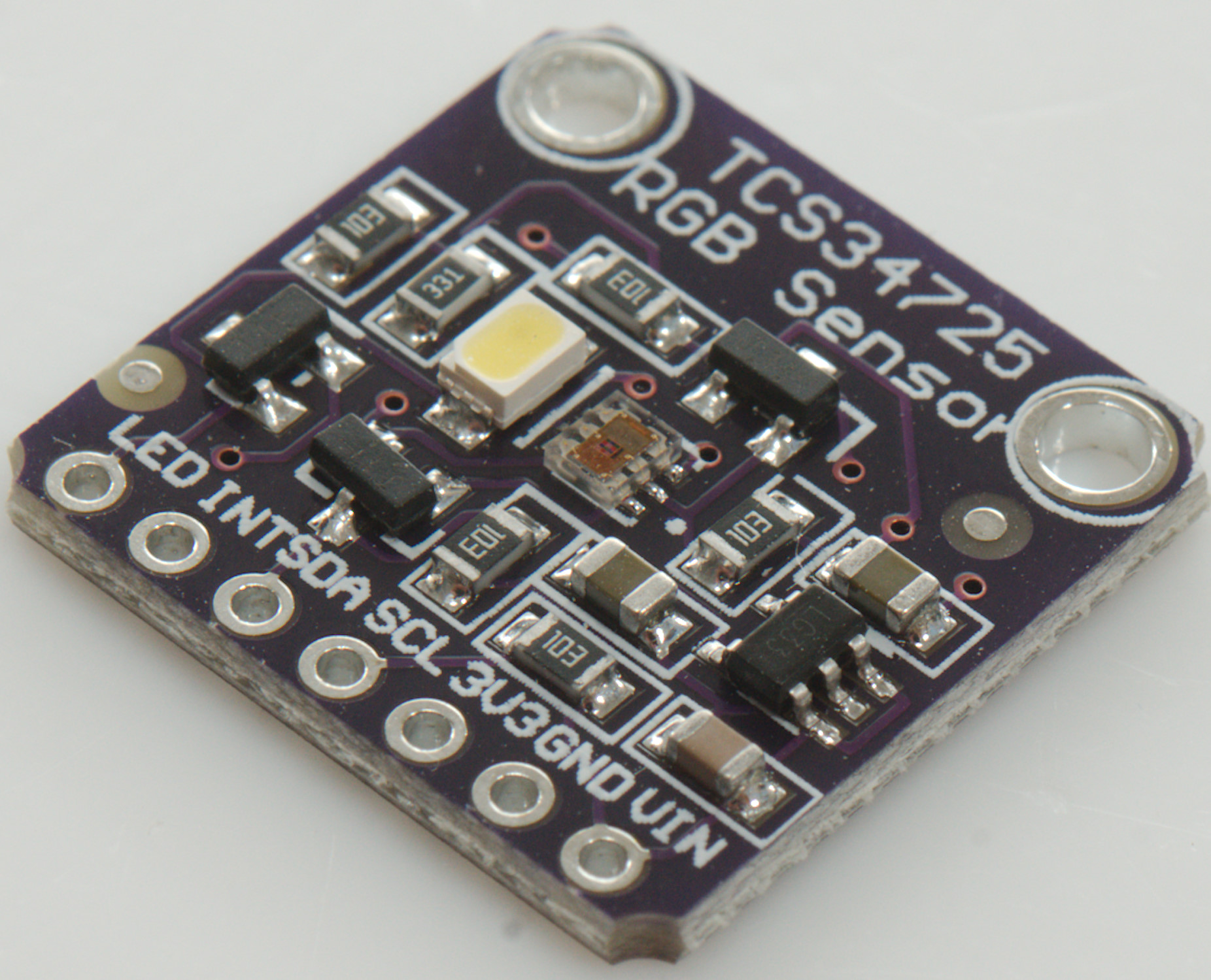
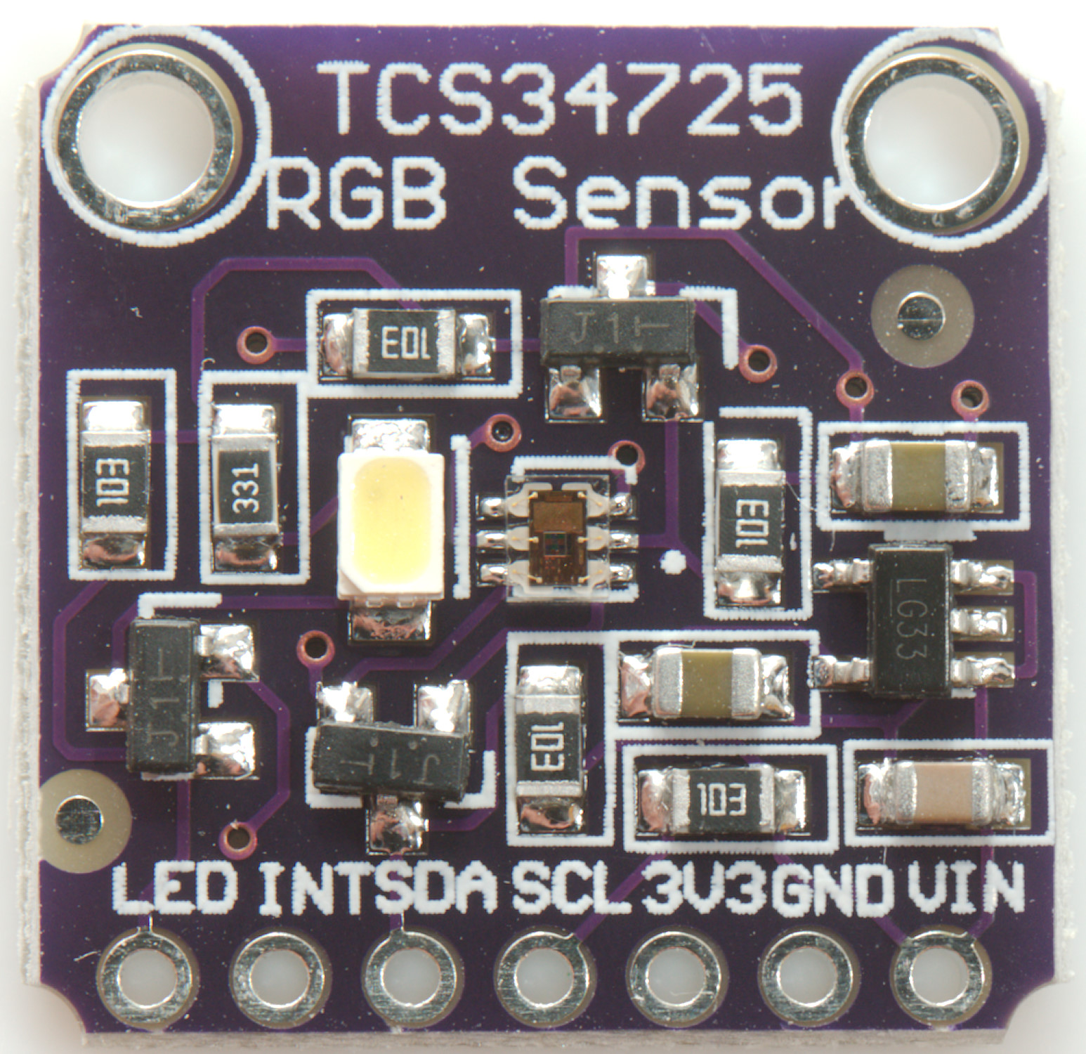
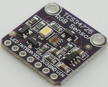
The sensor and module
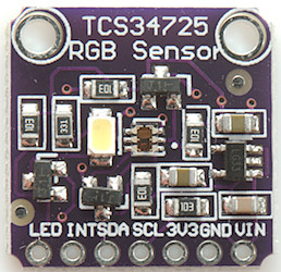
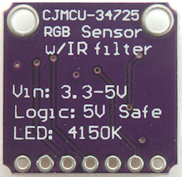
This is one module with the TCS34725 sensor and 3.3V to 5V conversion.
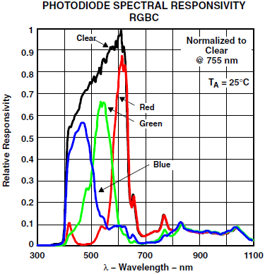
The 3 color sensors only has a small overlap, the clear (white) sensor covers the full range. The range matches the eyes range fairly well, but the eye do not split color the same way.
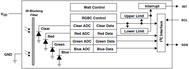
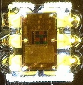
The chip has four inputs and four counters for the sensors, the final results depends on the gain and the integration time in addition to the light on the sensor.
The chip works in 2.4ms steps and for each step it can add a maximum of 1024 to the result, this means that the sample time must be 154ms before it can reach full range.
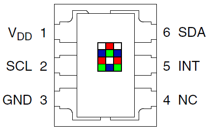
The chip is in a very small 6 pin package and is designed for 3.3V. Most modules has interface to 5V and some white LEDS to illuminate a surface.
The chip exist in four different versions:
- TCS34721: I2C address is 0x39, chip is for 3.3V operation.
- TCS34723: I2C address is 0x39, chip is for 3V operation with 1.8V communication.
- TCS34725: I2C address is 0x29, chip is for 3.3V operation.
- TCS34726: I2C address is 0x29, chip is for 3V operation with 1.8V communication.
I have only seen the TCS34725 chip and has hard coded the 0x29 address.
Requirements
- Can use any pins for communications, i.e. do not use the wire library.
- Do not use delay, but allows the sensor to work in the background.
- Easy configuration, basically time settings are done in milliseconds not with a couple of constants.
- Simple and fast way to read all RGBC values.
That was my initial requirements.
- A way to check for conversion done (There are two).
- Support all functions in the sensor.
- Conversion from RGB to a single color value (hue).
I added a couple more points during development
The library functions
Includes
Code:
#include <ColorSensorTCS34725.h>
The library is named after the chip with ColorSensor before the name.
Constants
- CS_GAIN_1: Input gain is 1
- CS_GAIN_4: Input gain is about 4 (3.8 - 4)
- CS_GAIN_16: Input gain is about 16 (15 - 16.8)
- CS_GAIN_60: Input gain is 60 (58 - 63)
The constants are defined as 0 to 3.
There are other constants, but they are for internal use.
Structures
RGBC
Code:
struct RGBC {
  uint16_t r;
  uint16_t g;
  uint16_t b;
  uint16_t c;
};
For returning values a structure is defined, this makes it possible to handle all values simultaneous.
LightValues
Code:
struct LightValues {
  uint16_t IR;
  double lux;
  uint16_t ct;
};
It is possible to estimate lux and color temperture using data from the sensor, this is done with the calcLight() function. It will return the above structure. The IR is how much light is outside the RGB bands.
All functions
Constructor
Code:
ColorSensorTCS34725(byte sda, byte scl);
The sensor uses I2C, but I have implemented it in software, this means any two pins can be used for it.
Integration time
Code:
  void setIntegrationTime(uint16_t ms);
  uint16_t  getIntegrationTime();
Integration time is how long it takes to read the light level, using longer time will make it more sensitive. This is linear, i.e. if a integration time of 200ms gives 500, then a integration time of 400ms will give 1000.
The actual setting is in 2.4ms step, the specified value will be rounded to nearest setting.
Lowest value is 3ms and below 154ms the maximum color values is limited.
Between 154ms and 614ms it is possible to reach 65535 for a channel.
When used with mains powered light it is a good idea to select the integration time as a number of full cycles, i.e. for 50Hz use n*20 and for 60Hz use n*16.67 to find a integration time (300 works for both)
Wait time
Code:
  void setWaitTime(uint16_t ms);
  uint16_t getWaitTime();
Between each integration the sensor can wait some time, this is to save power. The sensor has very low power consumption, this means this is seldom relevant.
The actual setting is in 2.4ms or 28.8ms steps, the specified value will be rounded to nearest setting.
Using 0 will disable the wait time and make the sensor do continuous integrations.
Below 610ms a 2.4ms resolution will be used and above a 28.8ms resolution will be used.
The maximum wait time is 7237ms, i.e. a bit above 7 seconds between each integration.
Average power consumption when running continuous is about 0.3mA dropping to 0.07mA at longest wait. This is for the sensor, any support circuit and leds will add to this.
Gain setting
Code:
  void setGain(byte gain);
  byte getGain();
  byte getGainFactor();
  void setArbitraryGain(uint16 gain);
  uint16_t getArbitraryGain();
The gain can be used to adjust sensitivity in four steps. setGain/getGain works with the CS_GAIN_n constants, to get the actual gain factor use getGainFactor() it will return 1, 4, 16 or 60.
The arbitrary gain uses both gain and integration time to set a gain between 1 (gain==1, integration time=154) to 240 (gain=60, integration time=614) in steps of 1.
Starting and stopping conversion
Code:
  boolean begin();
  void sleep();
Before the sensor can be used it must be started, this is done with "begin()". This will turn the converter on and start conversion cycles. It is possible to define integration time, wait time and gain before calling begin.
To turn the converter off use "sleep()", this reduces power consumption to about 0.003mA.
Interrupt value configuration
Code:
  void setInterruptFilter(byte samples);
  uint16_t getInterruptFilter();
  void setInterruptLow(uint16_t clearValue);
  uint16_t getInterruptLow();
  void setInterruptHigh(uint16_t clearValue);
  uint16_t getInterruptHigh();
To use the interrupt pin or the interrupt status bit there is 3 values to define.
The filter samples defines how many samples must be in range before interrupting:
0: Ignore low/high value and interrupt each time a conversion is done.
1-60: Require this number of samples with interrupt condition before interrupting (Values above 3 are rounded to nearest 5).
If the measured value on the clear channel is below "low" or above "high" it is a interrupt condition.
If "high" is below "low" the "high" value is disabled.
Interrupts
Code:
  void interruptPinEnable(boolean enable);
  boolean isInterrupt();
  void clearInterrupt();
The internal interrupt flags is always active and can be read and cleared with cs.isInterrupt() and cs.clearInterrupt(). To use the interrupt pin it must first be enabled with interruptPinEnable(true).
The interrupt signal can only be cleared by a special command, i.e. clearInterrupt(), this works both for the internal flag and the pin.
This library do not have any synchronization, i.e. be careful with using part of it from interrupt routines, it is better to set a flag and the handle it from loop().
Interrupt must be configured after begin has been called.
Checking isInterrupt() takes about 0.6ms on a 16MHz Arduino, use physical interrupt to avoid this delay.
Conversion ready
Code:
    boolean isReady();
    void clearReady();
The sensor has a flag to show when the first conversion is done and there is a valid value. To clear this flag the conversion must be stopped and restarted. This is not the most elegant way, an alternative is interrupt with filter==0, this can be used from software only or with interrupt.
Checking isReady() takes about 0.6ms on a 16MHz Arduino
Reading values
Code:
  RGBC readRGBC();
  uint16_t maxValue();
This call will read all four sensors and return a structure with the values. This function do not wait for any conversion, but will directly read the registers on the sensor. Conversions will update the registers in the background, use interrupt or isReady to detect when.
If any value reaches maxValue the sensor is overloaded and a lower gain setting is recommended. The maxValue will be 65535 if integration time is 154ms or above.
Advanced functions
Code:
  RGBC readRGBCRelative(RGBC ref);
  LightValues calcLight(RGBC values);
  int calcHue(RGBC values)
The readRGBCRelative() uses a previous measurement and calculates relative to that, when values are the same RGBC will all be 10000, lower values means they are lower and higher means they are higher. This can be used to save a calibration value from white light, then the relative values can be used to see how the actual color of the light with the calcHue() function.
The calcLight() will estimate lux and color temperature from a measurement, the values are returned in a struct.
The calcHue() will return the hue as a number between 0 and 360, this works best with relative values. If the difference between RGB values is very small it will return -1 instead of a hue value.
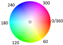
The hue is a rough match to the above color wheel.
Miscellaneous
Code:
  boolean isOnline()
  byte readReg(byte reg);
  void writeReg(byte reg, byte value);
  void serialPrintAllRegisters();
The isOnline function check if initialization worked and the status of the ACK flag from the last communication with the chip.
The other routines is mostly for testing and debugging, all functions in the sensor is covered by the other function in the library.
Examples
Examples are fairly short. The four fist is different ways to read the values, the two last shows some ways to use the values.
Reading sensor at any time
After initial startup time the sensor will always read valid values.
Code:
#include <ColorSensorTCS34725.h>

#define COLOR_SDA_PIN  12
#define COLOR_SCL_PIN  11

ColorSensorTCS34725 colorSensor(COLOR_SDA_PIN, COLOR_SCL_PIN);

void setup() {
  Serial.begin(9600);
  colorSensor.setWaitTime(0);
  colorSensor.setIntegrationTime(200);
  colorSensor.setGain(CS_GAIN_16);
  colorSensor.begin();
}

void loop() {
    RGBC v = colorSensor.readRGBC();
    Serial.print("Red: ");
    Serial.print(v.r);
    Serial.print("   Green: ");
    Serial.print(v.g);
    Serial.print("   Blue: ");
    Serial.print(v.b);
    Serial.print("   Clear: ");
    Serial.print(v.c);
    Serial.println();
    delay(2000);

}
Before starting the sensor it is best to define waiting time between conversion, integration time and gain, the values shown above is the default values.
Using waiting time will reduce the power consumption, but due to the low power consumption it will seldom be required.
Reading after a conversion
Use the isReady and setWaitTime functions to limit the read rate without blocking the Arduino.
Code:
#include <ColorSensorTCS34725.h>

#define COLOR_SDA_PIN  12
#define COLOR_SCL_PIN  11


ColorSensorTCS34725 colorSensor(COLOR_SDA_PIN, COLOR_SCL_PIN);

void setup() {
  Serial.begin(9600);
  colorSensor.setWaitTime(1000);  // Slow down conversion
  colorSensor.setIntegrationTime(1000); // Library will limit to maximum possible time
  colorSensor.setGain(CS_GAIN_16);
  colorSensor.begin();
}

long loopCount = 0;

void loop() {
  loopCount++;
  if (colorSensor.isReady()) {
    colorSensor.clearReady();
    RGBC v = colorSensor.readRGBC();
    Serial.print("Red: ");
    Serial.print(v.r);
    Serial.print("   Green: ");
    Serial.print(v.g);
    Serial.print("   Blue: ");
    Serial.print(v.b);
    Serial.print("   Clear: ");
    Serial.print(v.c);
    Serial.print("     loop was run: ");
    Serial.print(loopCount);
    Serial.println(" times");
    loopCount = 0;
  }
}
Before starting the sensor it is best to define waiting time between conversion, integration time and gain.
Using interrupt
Using interrupt means the processor uses no time on checking the ready state.
Code:
#include <ColorSensorTCS34725.h>

#define COLOR_SDA_PIN  12
#define COLOR_SCL_PIN  11
#define COLOR_INTERRUPT_PIN 2

ColorSensorTCS34725 colorSensor(COLOR_SDA_PIN, COLOR_SCL_PIN);
boolean colorReady = false;

void colorInterrupt() {
  colorReady = true;
}

void setup() {
  Serial.begin(9600);
  colorSensor.setWaitTime(1000);  // Slow down conversion
  colorSensor.setIntegrationTime(1000); // Library will limit to maximum possible time
  colorSensor.setGain(CS_GAIN_16);
  colorSensor.begin();
  pinMode(COLOR_INTERRUPT_PIN, INPUT_PULLUP);
  attachInterrupt(digitalPinToInterrupt(COLOR_INTERRUPT_PIN), colorInterrupt, FALLING);
  colorSensor.interruptPinEnable(true);
}

long loopCount = 0;

void loop() {
  loopCount++;
  if (colorReady) {
    colorSensor.clearInterrupt();
    colorReady = false;
    RGBC v = colorSensor.readRGBC();
    Serial.print("Red: ");
    Serial.print(v.r);
    Serial.print("   Green: ");
    Serial.print(v.g);
    Serial.print("   Blue: ");
    Serial.print(v.b);
    Serial.print("   Clear: ");
    Serial.print(v.c);
    Serial.print("     loop was run: ");
    Serial.print(loopCount);
    Serial.println(" times");
    loopCount = 0;
  }
}
Using interrupt pin, but not interrupt
Using the interrupt pin is nearly as fast as using interrupt and this means any digital input pin on the Arduino can be used.
Code:
#include <ColorSensorTCS34725.h>

#define COLOR_SDA_PIN  12
#define COLOR_SCL_PIN  11
#define COLOR_INTERRUPT_PIN 2

ColorSensorTCS34725 colorSensor(COLOR_SDA_PIN, COLOR_SCL_PIN);

void setup() {
  Serial.begin(9600);
  colorSensor.setWaitTime(1000);  // Slow down conversion
  colorSensor.setIntegrationTime(1000); // Library will limit to maximum possible time
  colorSensor.setGain(CS_GAIN_16);
  colorSensor.begin();
  pinMode(COLOR_INTERRUPT_PIN, INPUT_PULLUP);
  colorSensor.interruptPinEnable(true);
}

long loopCount = 0;

void loop() {
  loopCount++;
  if (!digitalRead(COLOR_INTERRUPT_PIN)) {
    colorSensor.clearInterrupt();
    RGBC v = colorSensor.readRGBC();
    Serial.print("Red: ");
    Serial.print(v.r);
    Serial.print("   Green: ");
    Serial.print(v.g);
    Serial.print("   Blue: ");
    Serial.print(v.b);
    Serial.print("   Clear: ");
    Serial.print(v.c);
    Serial.print("     loop was run: ");
    Serial.print(loopCount);
    Serial.println(" times");
    loopCount = 0;
  }
}
Detecting colors
Code:
#include <ColorSensorTCS34725.h>

/*
  To use in reflective mode (Works best with low ambient light):
  White led must be on (LED module pin unconnected or connected to a HIGH Arduino pin)
  Place white paper over sensor
  Reset Arduino
  Serial terminal will start listing values around 10000 (8000-12000)
  Remove white paper
  Place any color item above the sensor and it will measure the color

To measure light color
  White led must be off (LED module pin connected to GND or a LOW Arduino pin)
  Illuminate sensor with white light at about same brightness as lists to test.
  Reset Arduino
  Serial terminal will start listing values around 10000 (8000-12000)
  Remove white light
  Aim colored light at sensor and it will measure the color
*/

#define COLOR_SDA_PIN  12
#define COLOR_SCL_PIN  11

ColorSensorTCS34725 colorSensor(COLOR_SDA_PIN, COLOR_SCL_PIN);

RGBC colorRef;

void setup() {
  Serial.begin(9600);
  colorSensor.setWaitTime(0);
  colorSensor.setIntegrationTime(200);
  colorSensor.setGain(CS_GAIN_16);
  colorSensor.begin();

  delay(2000);
  colorRef = colorSensor.readRGBC();
}

void loop() {
  if (colorSensor.isReady()) {
    colorSensor.clearReady();
    RGBC v = colorSensor.readRGBCRelative(colorRef);
    Serial.print("Red: ");
    Serial.print(v.r);
    Serial.print("   Green: ");
    Serial.print(v.g);
    Serial.print("   Blue: ");
    Serial.print(v.b);
    Serial.print("   Clear: ");
    Serial.print(v.c);
    Serial.print("   Hue: ");
    int hue = colorSensor.calcHue(v);
    Serial.print(hue);
    if (hue >= 330 || hue < 30) Serial.print(" red");
    if (hue >= 30 && hue < 90) Serial.print(" yellow");
    if (hue >= 90 && hue < 150) Serial.print(" green");
    if (hue >= 150 && hue < 210) Serial.print(" cyan");
    if (hue >= 210 && hue < 270) Serial.print(" blue");
    if (hue >= 270 && hue < 330) Serial.print(" magenta");
    Serial.println();
    delay(2000);
  }
}
Estimating lux and color temperature (CT)
Code:
#include <ColorSensorTCS34725.h>

#define COLOR_SDA_PIN  12
#define COLOR_SCL_PIN  11

ColorSensorTCS34725 colorSensor(COLOR_SDA_PIN, COLOR_SCL_PIN);

void setup() {
  Serial.begin(9600);
  colorSensor.setWaitTime(1000);  // Slow down conversion
  colorSensor.setIntegrationTime(1000); // Library will limit to maximum possible time
  colorSensor.setGain(CS_GAIN_16);
  colorSensor.begin();
}

void loop() {
  if (colorSensor.isReady()) {
    colorSensor.clearReady();
    RGBC v = colorSensor.readRGBC();
    LightValues lv = colorSensor.calcLight(v);
    Serial.print("Lux: ");
    Serial.println(lv.lux, 0);
    Serial.print("CT: ");
    Serial.println(lv.ct);
    Serial.println();
    delay(2000);
  }
}
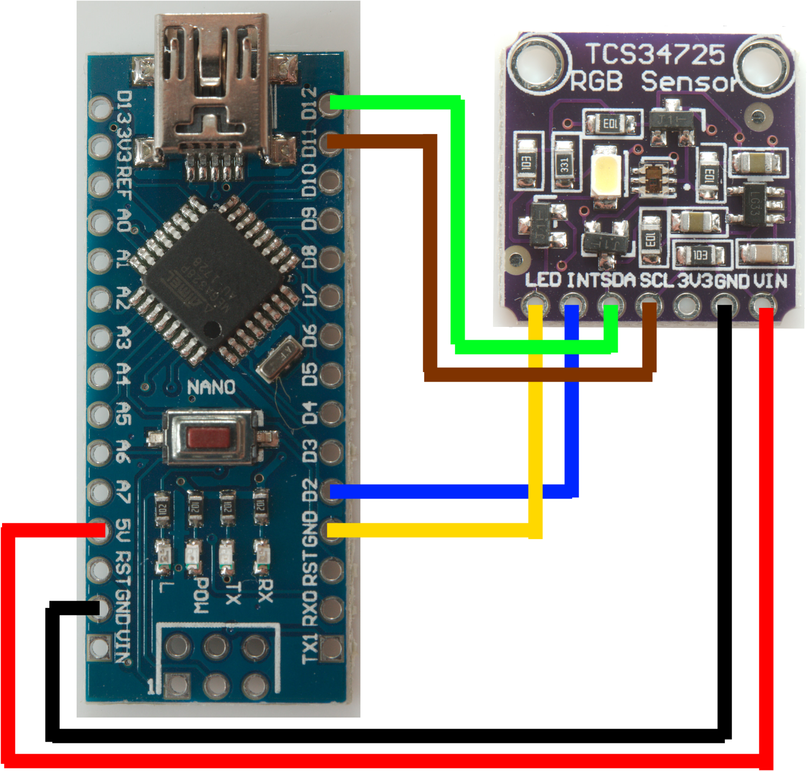
My test setup

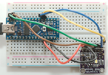
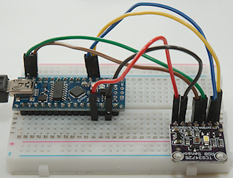
The yellow wire is only connected when I want the LED off. It could be controlled from a Arduino pin (This is not part of the library).
Conclusion
With this library I can easily use the MAX34725 sensor for a couple of different applications and modules will work with 2, 3 or 4 wire connections (SDA, SCL, Interrupt, LED).
Notes and download
I have used this library with Nano, Nano Every and ProMicro, but I expect it to work with any Arduino
Download library