Digital Relay 4 Channels 12V
I needed to turn on/off some devices from a 3.3V microprocessor, but the devices needed 12V and much more current than the microprocessor can deliver. The simplest way to do that is with a MOSFET that turns on below 3.3V gate voltage. I did not want to do that, I wanted to use any standard MOSFET and to turn it fully on for lowest power loss.
Contents
Requirements
Design/Schematic
PCB
Testing
Applications
Conclusion
Notes and downloads
Requirements
- Must work with 12V
- Easy connection for thicker wires on the 12V side, both input and output (i.e. screw terminals).
- Input must be controllable from 3.3V and 5V microprocessors.
- Must be able to handle inductive loads.
- Must be able to handle a couple of amperes.
- Output must not turn on during power on or if unconnected.
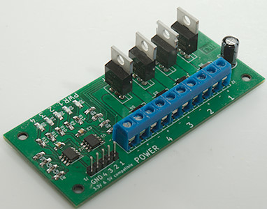
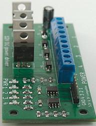
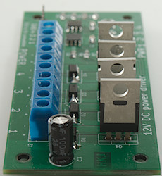
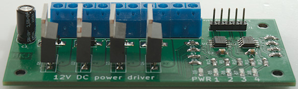
- I needed 4 channels.
- Indicator lights.
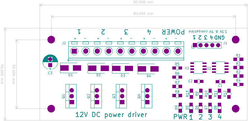
Design/Schematic
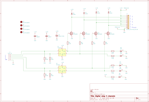
It was fairly simple to design, a standard MOSFET driver do the level translation from 3.3V to 12V. I placed the indicator leds after the drives, i.e. the leds will only turn on when the MOSFET have gate voltage. I also added a led for indicating that 12V was connected. To handle inductive loads I placed diodes.
The different component in the schematic, the actual values is not very important:
- R1..R4: Pulldown, this can be anything from a few kOhm to Mohm.
- R5..R8: Gate resistor, a low value means fast turn on/off and lot of radio noise, increasing the value will slow down the on/off, increase the heat during transition and reduce the radio noise.
- R9..R13: Led resistors, values from 1kOhm and up can be used, it defines the brightness of the led.
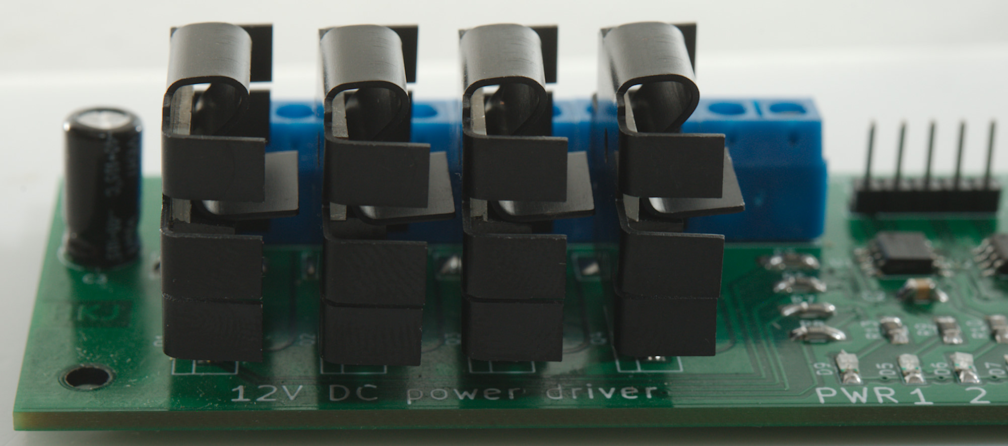
- Q1..Q4: MOSFET transistors, any standard N-Channel TO220 will work.
- C1..C2: Decoupling for the drivers, they provide power for the driver to switch output in less than a 0.1 microsecond
- C3: Power decoupling, will stabilise the voltage a bit during transitions and keep inductive spikes from supply cables down.
- U1..U2: The drivers, the important part is the pinout and that they are non-inverting.
- D1..D4: Fast diodes that can handle a couple of amperes.
- D5..D9: Standard leds, any color will work.
Resistors, 100nF capacitor and leds are all 0805 size parts. For the diodes I have used a SMB footprint.
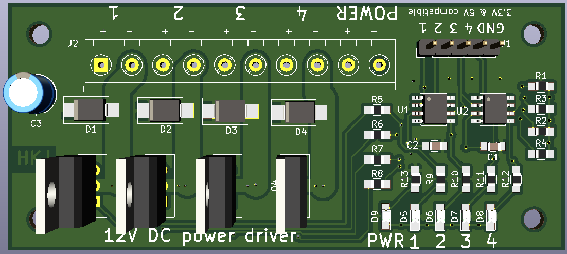
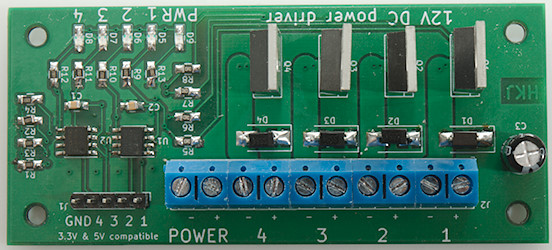
PCB

I did not make the PCB really compact, I wanted space for writing the channel numbers and other information.

The different functions are grouped together: All pullup resistors are in line, all gate resistors are in line, all led resistors are in line, etc.. To handle high current I made the top side a +12V plane and the bottom a GND plane. The output from the MOSFET is done with very thick tracks and connected on both sides of the circuit board.
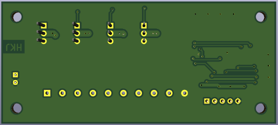
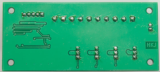
I tried to route most stuff on the topside to get a good GND around the MOSFET transistors.
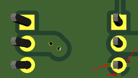
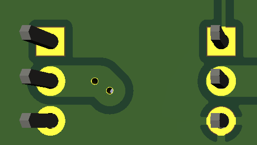
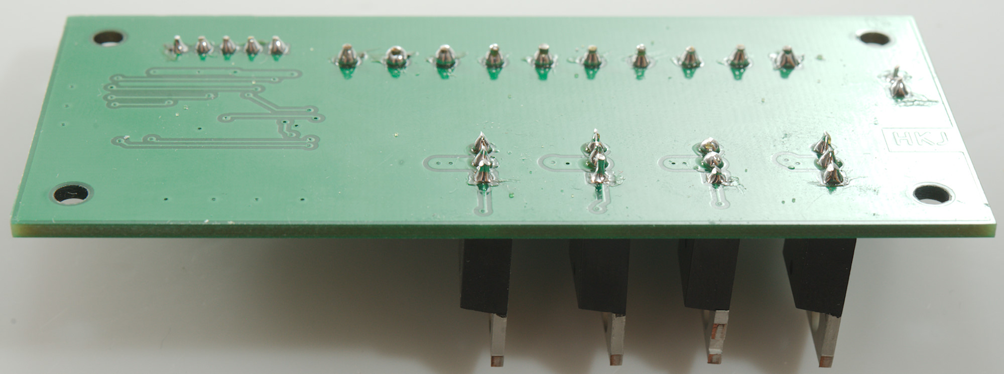
I did make one mistake in the layout, my PCB was with thermal relief (This is the default). This means that only a couple of thin connection are made to the MOSFET pin. I have changed that, it makes it a bit harder to solder, but is better for high current.
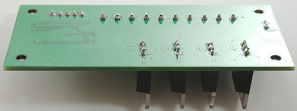
Oops, I can see a bad solder joint.
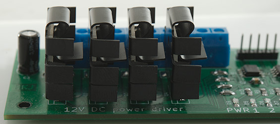
It is possible to use small heatsinks on the MOSFETS, but it is a bit risky* because they will touch the next MOSFET if the legs bends.
*Nothing will blow up, but it may link outputs together.
Testing
A was curious about the MOSFET transistors, they are marked IRF3205, but are from EBAY. I measured the RDSon to about 26mOhm (Supposed to be 8mOhm) with 12V on gate at 5A, this means they are NOT IRF3205.
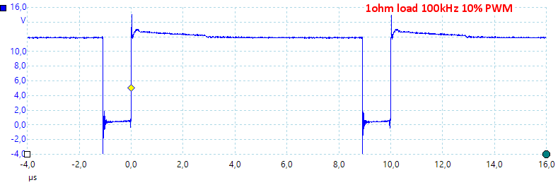
Using 100kHz 10% PWM with a 1ohm load on a 12V supply. The PWM signal is from a 3.3V processor. The raise and fall times (turn on/turn off) times are fast and I get some inductive kickback from the wires and from my 1ohm resistor. The resistor is not 1ohm at this frequency, average current is only 0.5A.
Note: The current is running when the signal is low.
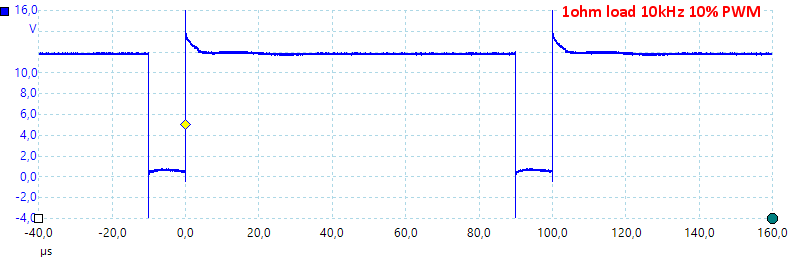
Reducing the PWM frequency to 1kHz bought the current to 0.9A, this is more realistic (There is some resistance in my test wires and alligator clips, the MOSFET and the circuit board).
For the above two test I used a 70000uF capacitor over the supply voltage close to the PCB.
Applications
It will work safely with up to 15V supply voltage and may work down to 5V, but it depends on the used MOSFETs.
Input can be from either a 5V or 3.3V microprocessor.
Output can be used to driver small DC motors, relays or 12V LED-Strips.
With motors and leds it is possible to use PWM from a microprocessor to regulate.
Conclusion
I got the driver I wanted and it works nicely.
Notes and downloads
Gerber
KiCad project