| Reference | Number of | Component |
|---|---|---|
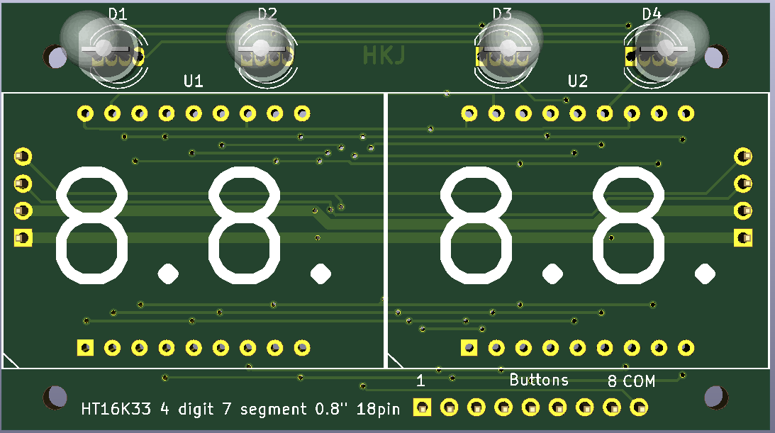
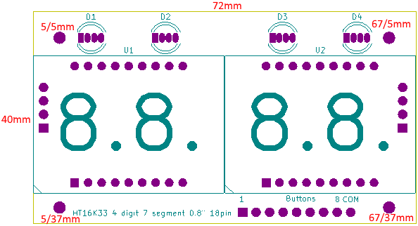
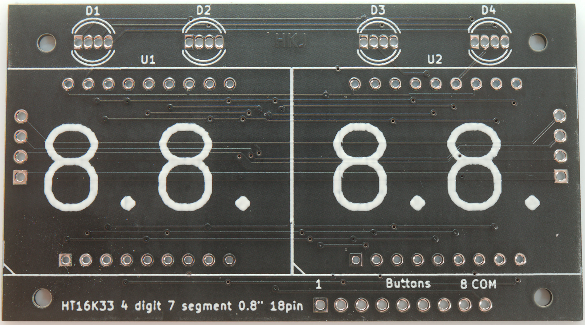
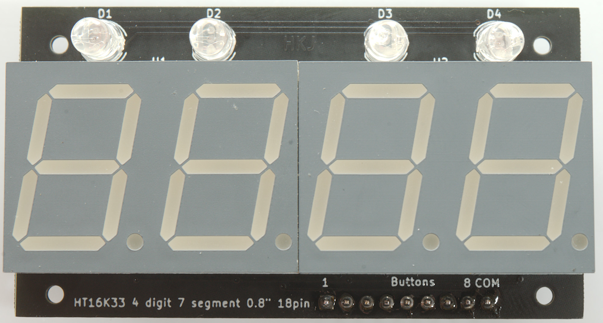
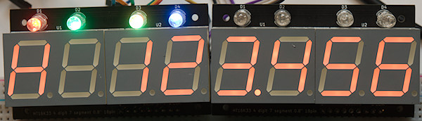
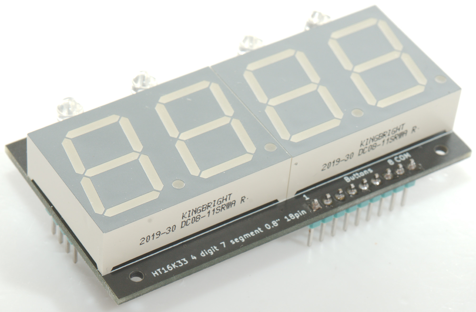
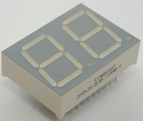
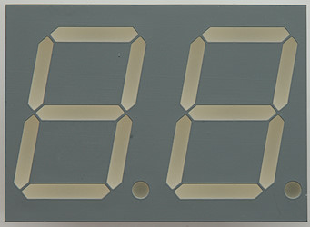
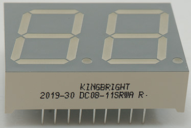
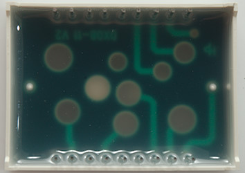
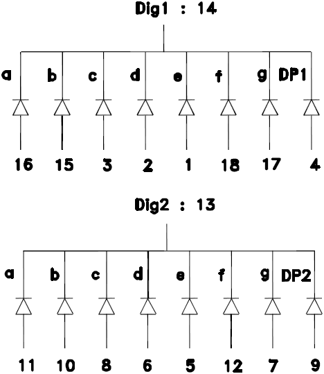
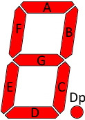
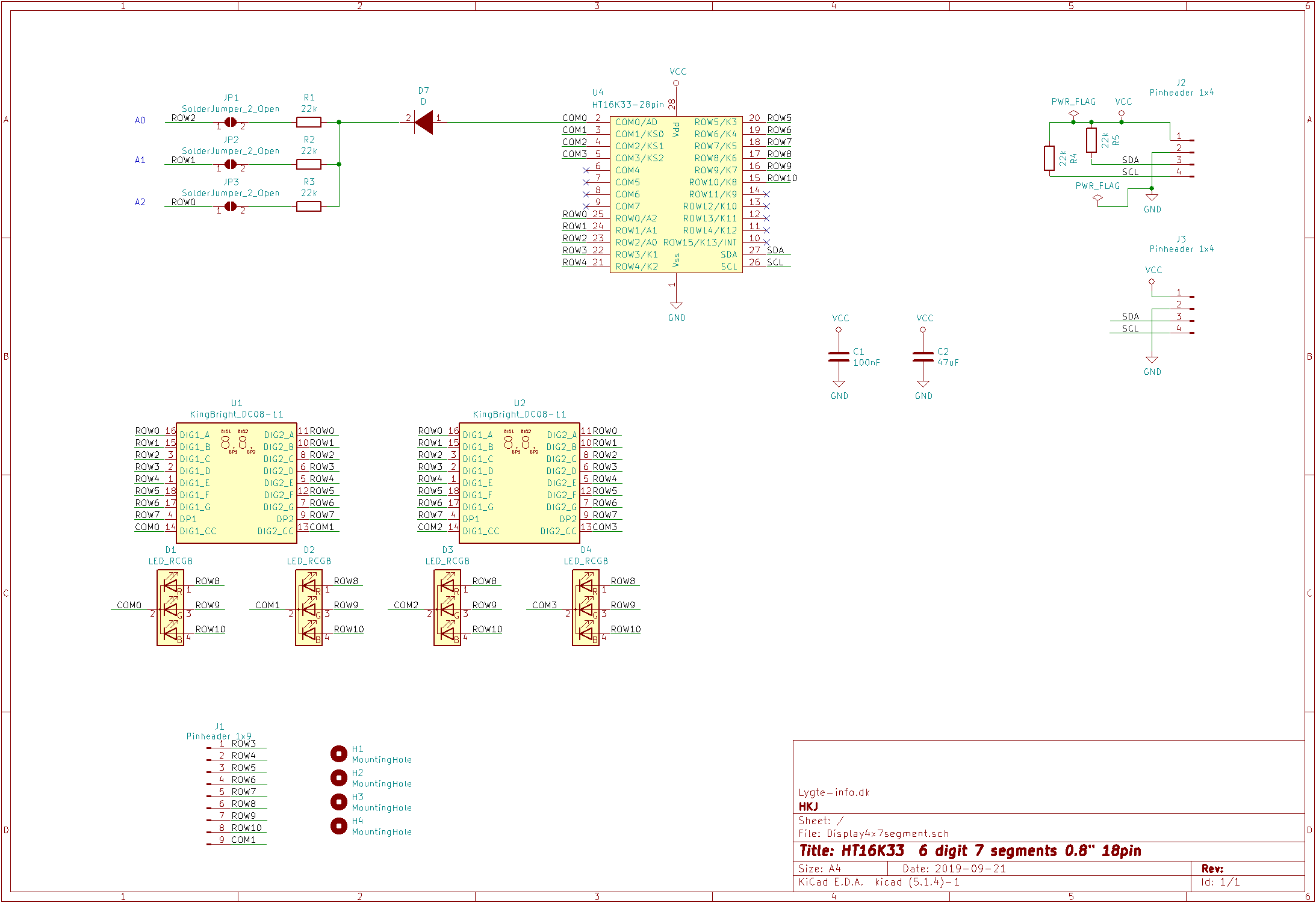
| U1, U2 | 2 | KingBright DC08-11 any color or similar (pinout is fairly standard) |
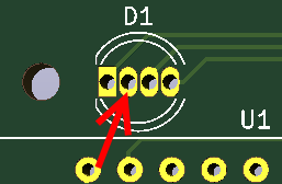
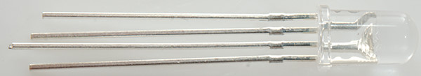
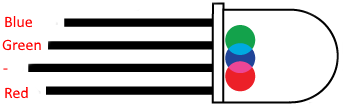
| D1, D2, D3, D4 | 4 | RGB 5mm led |
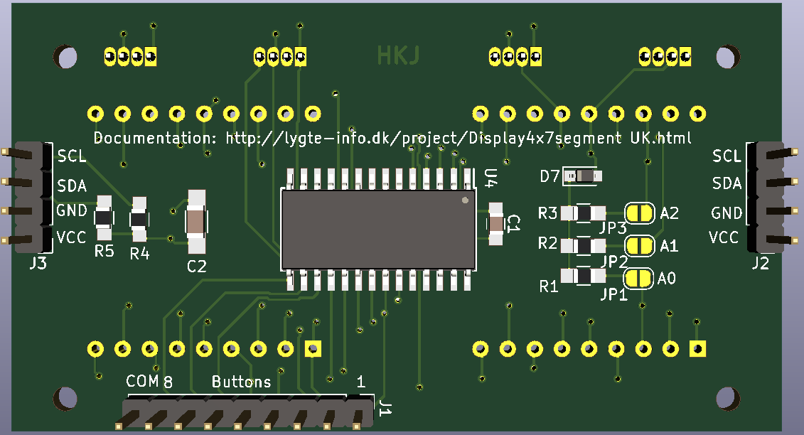
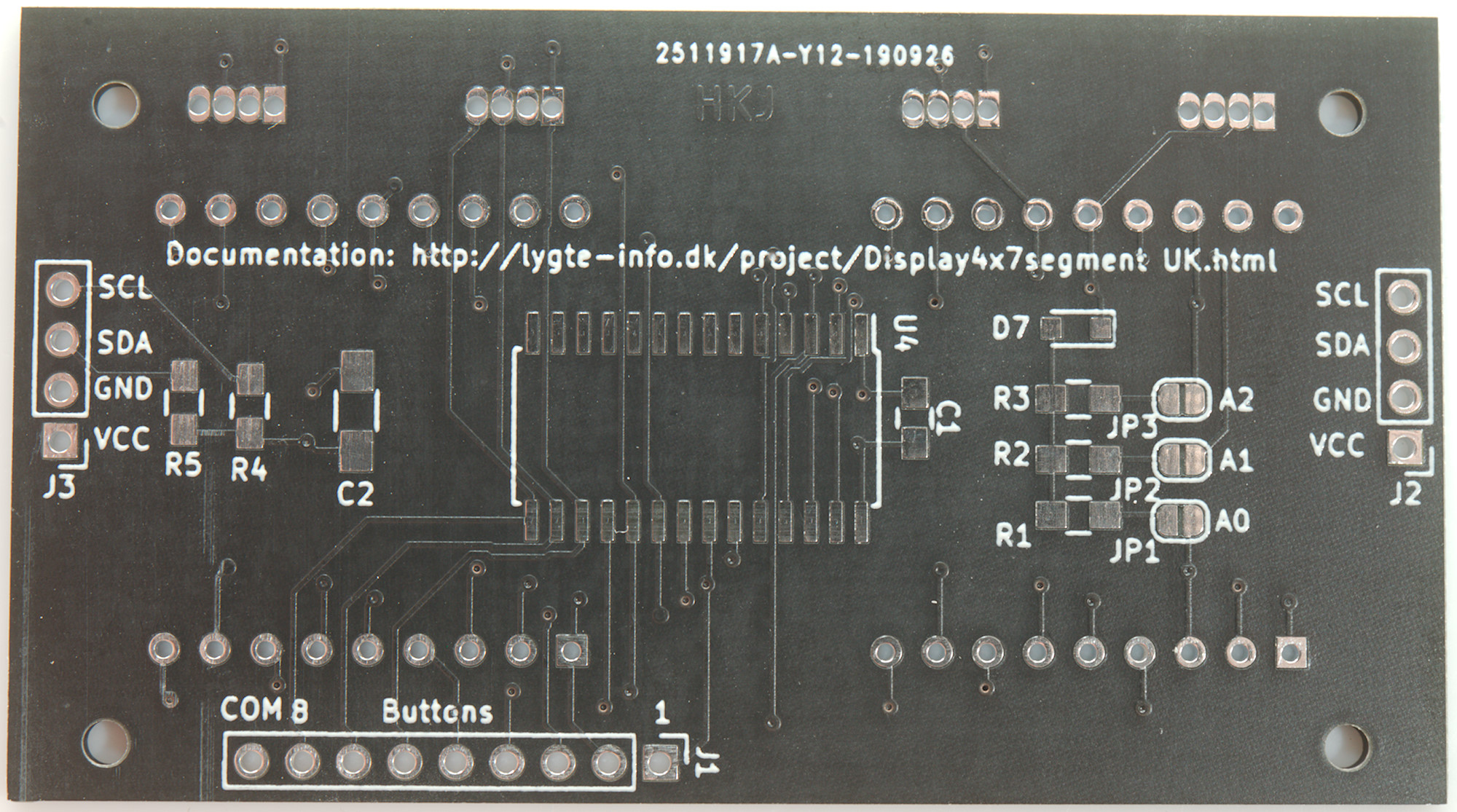
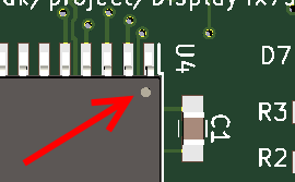
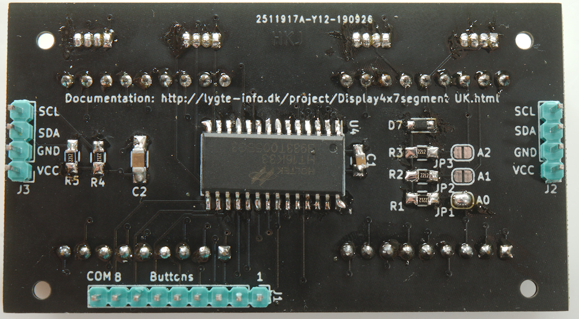
| U4 | 1 | HT16K33 28 pin |
| R1, R2, R3, R4, R5 | 5 | 22kohm 0805 |
| C1 | 1 | 100nF 0805 |
| C2 | 1 | 47uF 1206 (Smaller capacity can be used) |
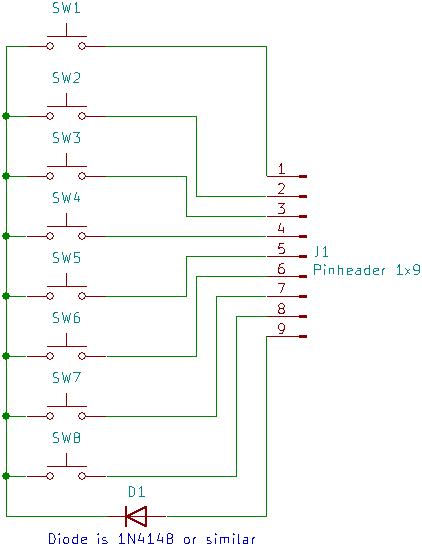
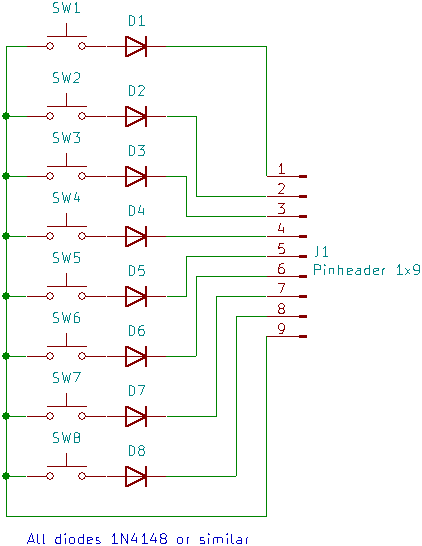
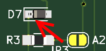
| D7 | 1 | 1N4148 diode SOD323 or other small diode. |
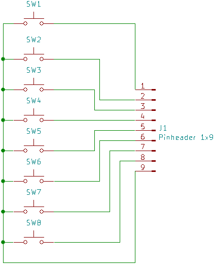
| J1 | 1 | 9 pin strip |
| J2, J3 | 2 | 4 pin strip |