Electronic Load XY-FZ25
In this project I make a small electronic load for battery testing where the curves can be logged on a computer. The project consist of connecting a electronic load module to a serial to USB cable and putting it into a box. There is a little bit of soldering involved.
I expect this will work on Windows, Linux and Mac computers, but have only tested on Windows.
Contents
Parts needed
Electronic load XY-FX25 module
Serial to USB cable
Enclosure
TestController
Some testing on the module
Conclusion
Notes & Download
Parts needed
- Electronic load XY-FX25, can be found on Aliexpress or Ebay for less than $15
- A 3.3V serial to USB cable, can be found on Aliexpress or Ebay for less than $15
- Two binding posts. Box is made with 6.5mm mounting holes.
- A 3D printed box.
- Four self tappers, ø3mm x 30mm.
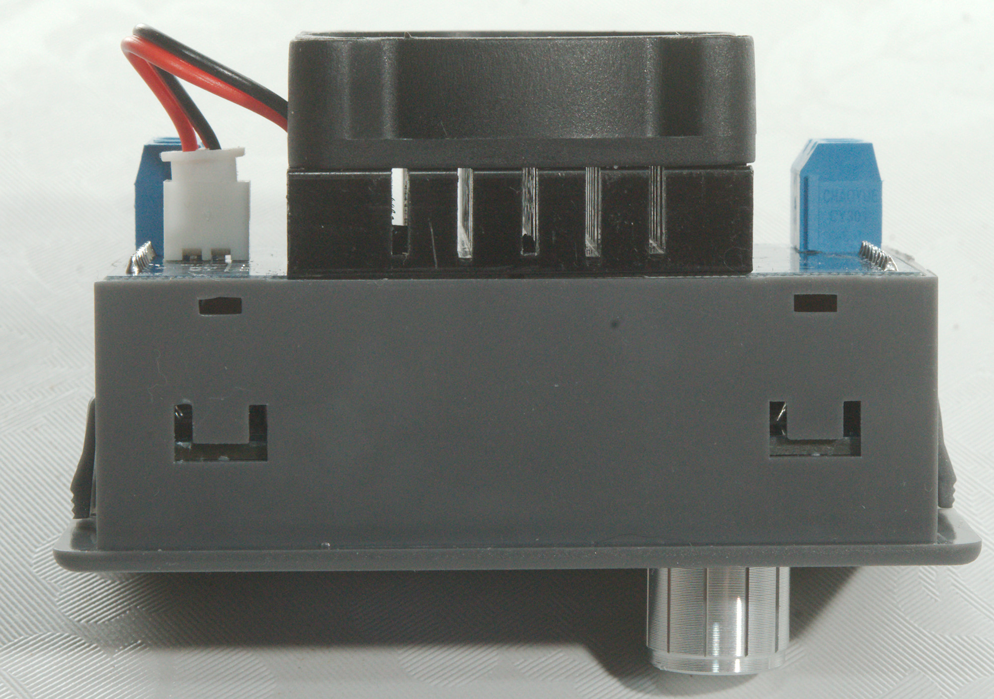
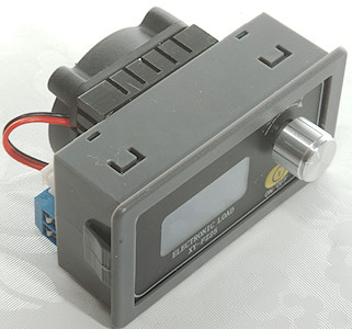
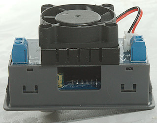
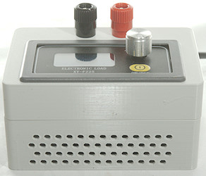
Electronic load XY-FX25 module
This model exist in both FX25 & FX35 version, the FX35 has a better fan and is rated for slightly higher power and and current.
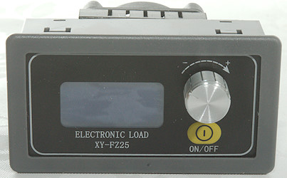
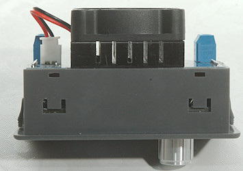


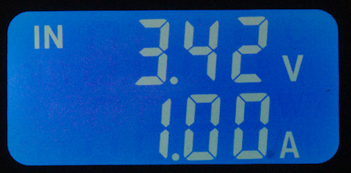
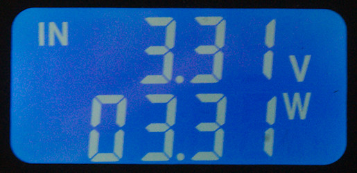
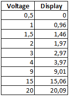
The display is fairly simple with two lines of text, the top line shows voltage, the bottom line can be switches between different readings by pressing the knob.
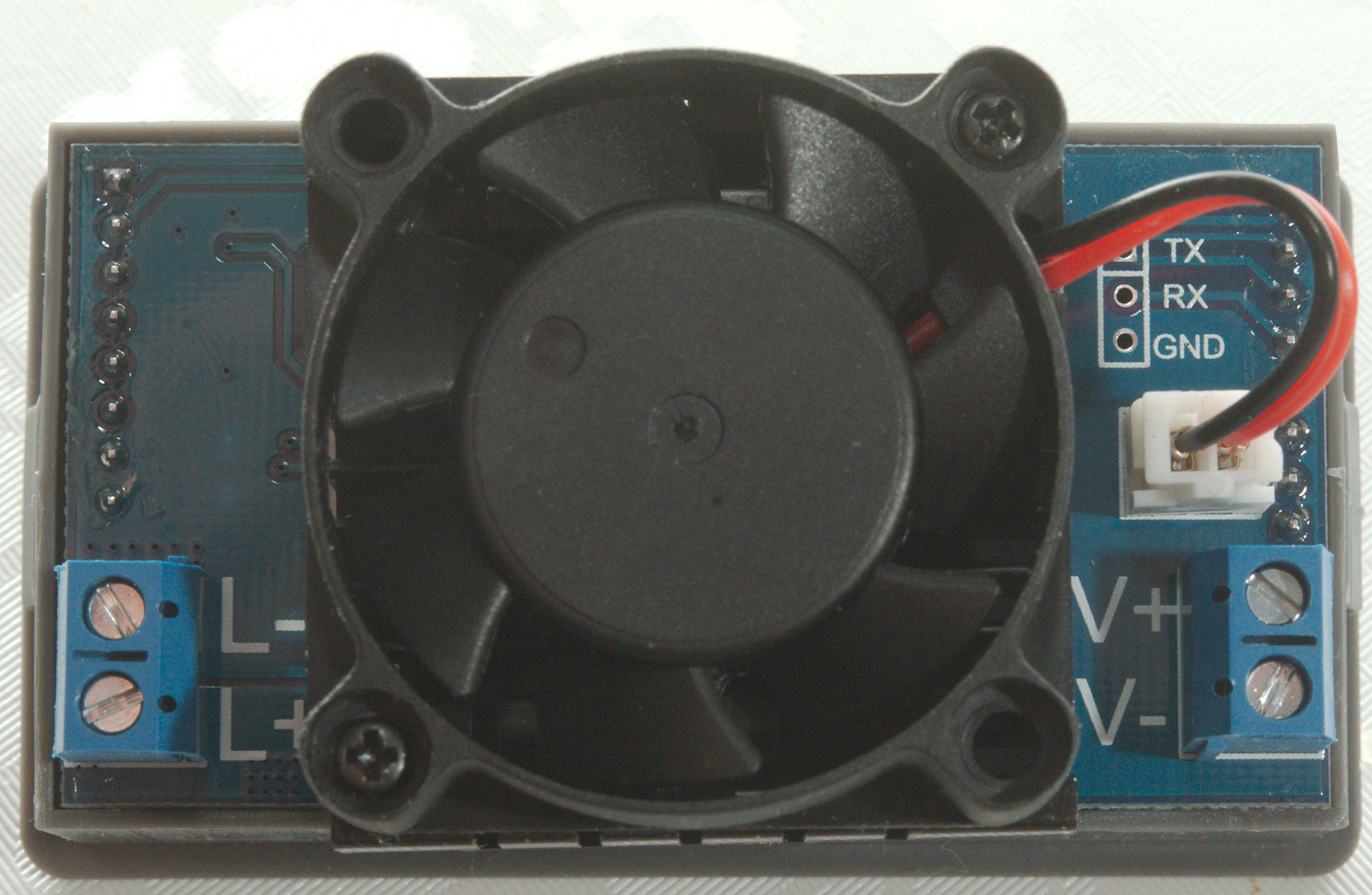
Serial to USB cable
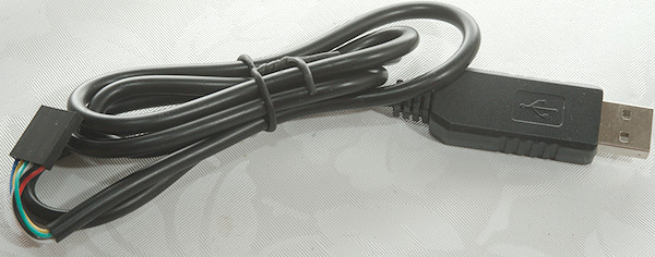
The USB conversion is a standard 3.3V serial to USB cable with 6 wires (I only need to use 4 of them).
The cable outputs 5V on the supply line and 3.3V on the serial line.
If the cable outputs 5V on the signal line a 10kOhm resistor between the cable and the RX point on the module will fix it.
Search for something like "6Pin FTDI FT232RL Modul" on ebay will show lots of these cables.
I use it to supply power to the module in addition to the computer connection.
Due to the fan power it is best to connect the USB directly to the PC or to a powered USB hub.
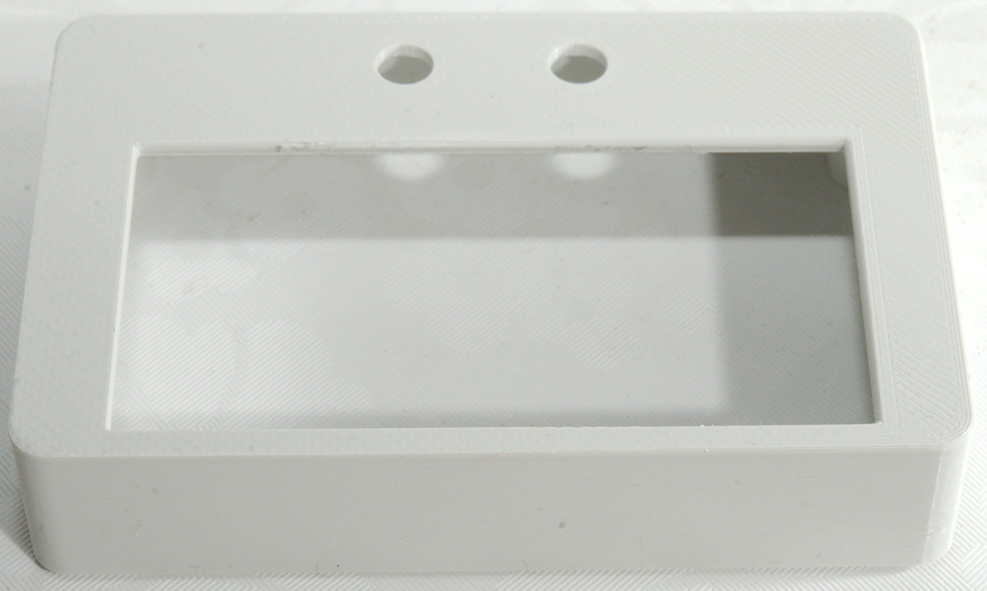
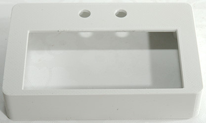
Enclosure
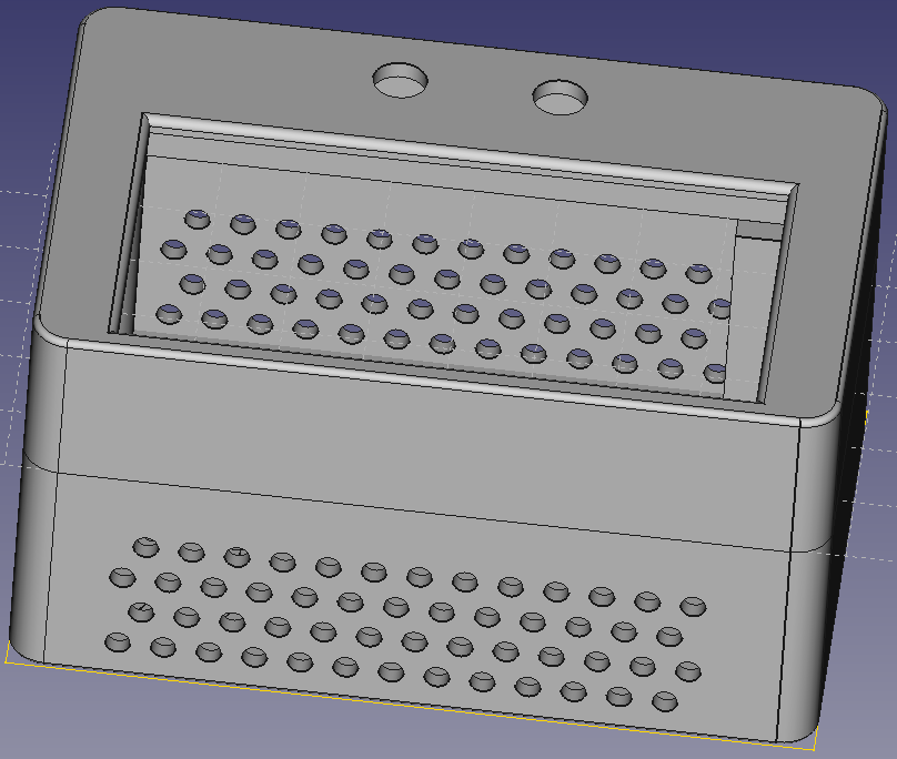
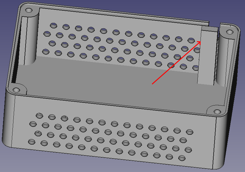
The box is a fairly simple design with holes for the module and for two binding posts. The bottom is perforated to allow some cooling, it is not good enough to handle the full power of the load, but it is good enough for testing small batteries.
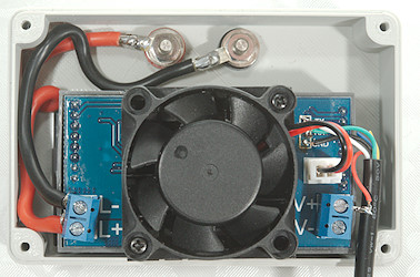
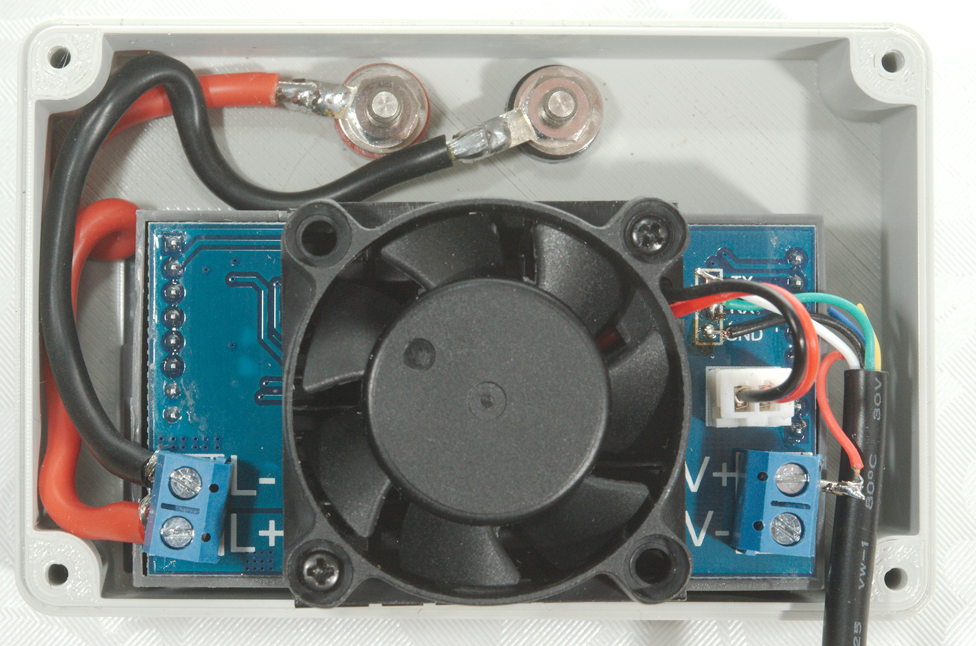
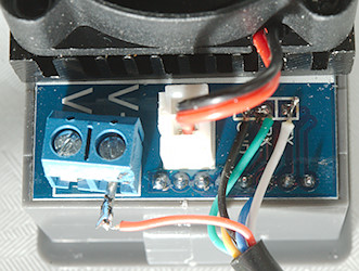
The module clicks into the box (The fan & heatsink was a bit tight to push in), the binding post screws in and wires are mounded from them to the L marked terminals.
The pillar in the box is a simple strain relief for the USB cable
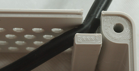
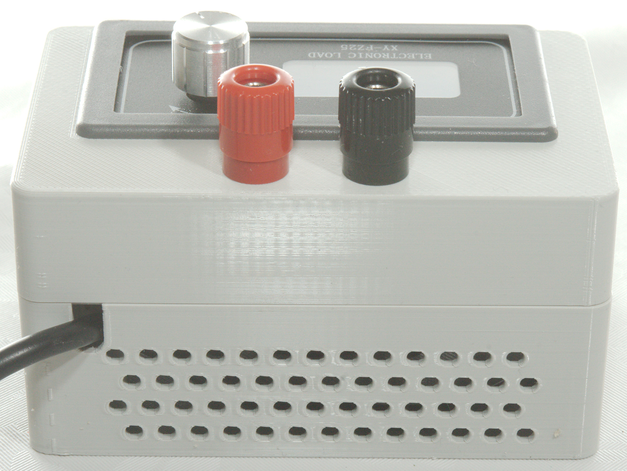
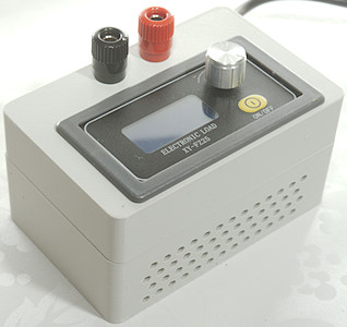
As can be seen here.
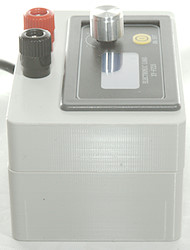


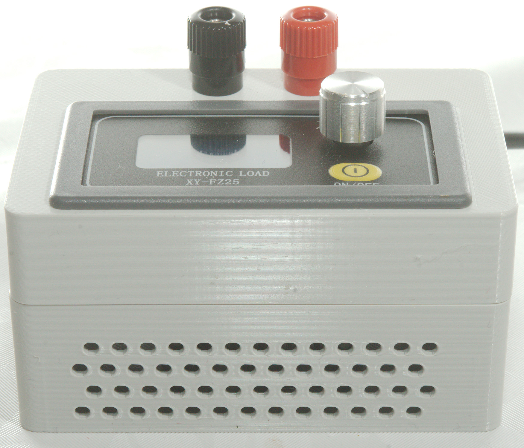
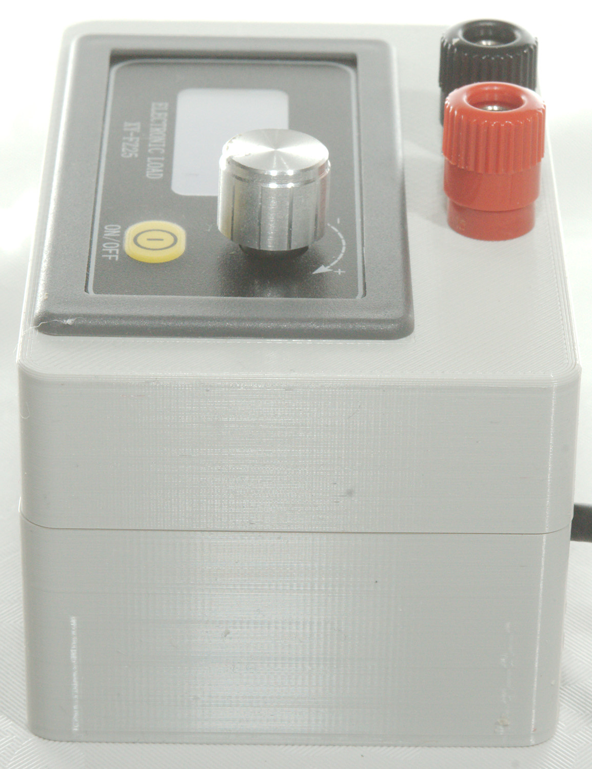
The finished load.
TestController
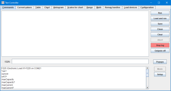
To use the load from a computer I uses TestController, it supports lots of different devices and I have added support for FZ25 & FZ35.
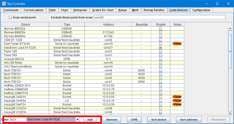
To use the load select the "Load devices" page and type "FZ25" in the filter box. This will select the load (If another FZ25 devices is shown in the combobox, change it to the load), then it can be added with the Add button.
In the list above type the com port for the load in the address field. To get a list of com ports, press F2 to enter edit mode, then use the right mouse button to show a list of possible com ports.
Finally press "Reconnect" and the load is ready for use.
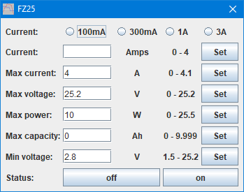
Using the Setup button it is possible to configure the load. I have reduced the maximum power to 10 Watt and adjusted the minimum voltage to 2.8V for a LiIon test.
The load do not have read back of selected current, for this reason this panel will not show selected current.
Due to the way the load works the connection is not 100% reliable, sometimes a field may be be filled or a request to change a parameter may fail.
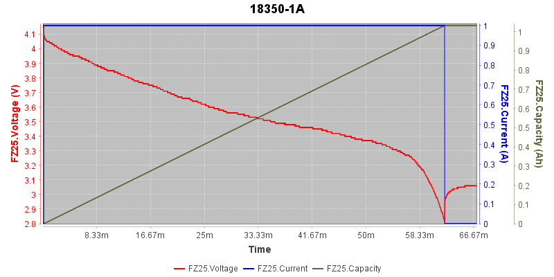
A discharge of a 18350 at 1A.
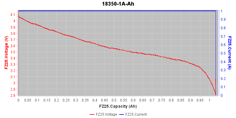
Same discharge, but viewed with capacity Y-scale.
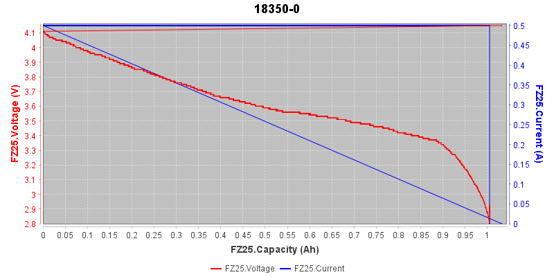
0.5A discharge with capacity scale.
Some testing on the module
- Current consumption idle: 5V 24mA
- Current consumption on: 5V 160mA, peak about 210mA when starting fan.
- Load current when load is off is about 0.1mA at 10V, i.e. about 10kOhm.
- Fan has a low noise level.
- Fan is partly temperature controlled.
Due to the fan power consumption this load is best connected directly to a computer or to a powered USB hub.
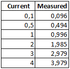
It is not a precise load, but good enough for checking batteries (Do not expect a analyzing charger to be better) in the range 0.1A to a few A (max 5W in PLA box).
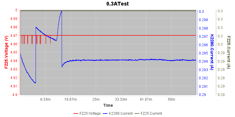
A 0.3A test, the variation is about 9mA or 3%, the average is 6mA too low or 2% (Note: The current scales range are 10mA from top to bottom).
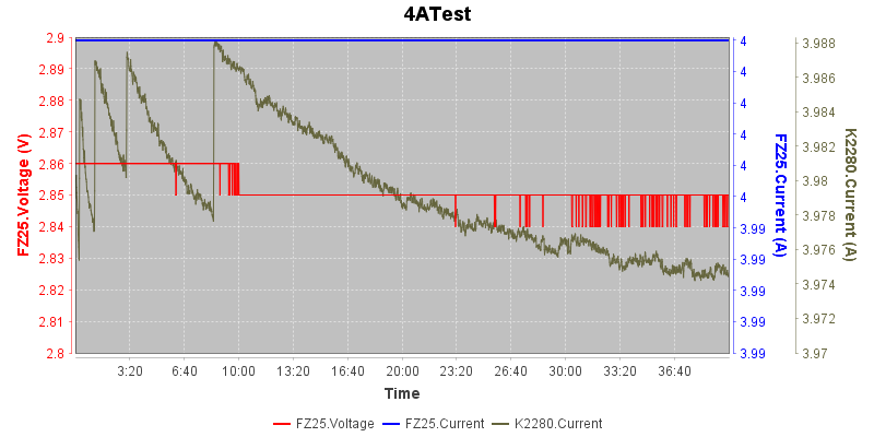
A 4A test, the load terminated shortly after the 40 minutes, probably due to over temperature.
The total current variation is 14mA or 0.35%. Average is 20mA low or 0.5%.
The power level (12 watt) and heat was too high for the PLA box, it was deformed.
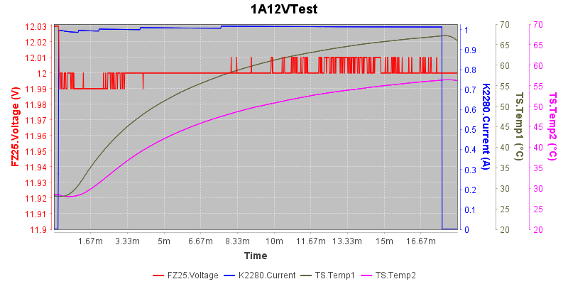
A temperature test, I uses two thermocouplers, one inside the heatsink and on in a bottom corner of the box. I used 1A and 12V i.e. 12W and the load disabled itself after 17 minutes with a over temperature warning. Generally it is not recommended to use PLA above 50°C and as can be seen on the two temperature curves the temperature was way higher.
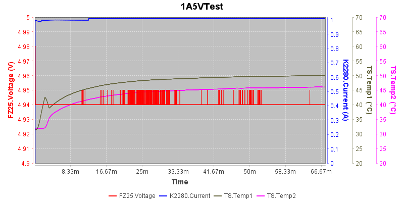
Same test as above, but with 1A and 5V, i.e. 5W, the temperature inside the heatsink reaches 50° and the box is a bit cooler, this is fairly safe for a PLA box.
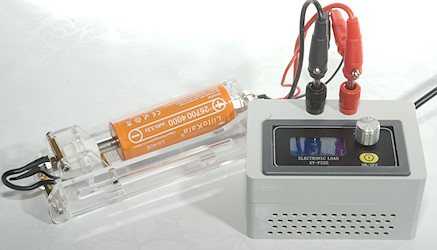
This battery holder is very nice, but a bit over kill for this load, because it cannot use the 4-terminal connection.
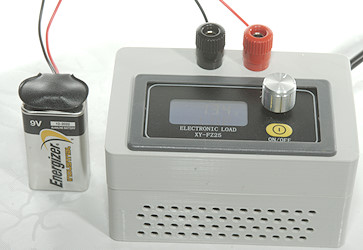
Any battery with wire connections can easily be test when using binding post, here it is a 9V battery with a standard clip.
Conclusion
This load can be made for about $30, a finished electronic load (that is much better) is $150 or more (TestController supports some fairly cheap modes: Kunkin KP184, Korad KEL103).
For getting a cheap way to test batteries and log the result on a computer this load is feasible.
Besides the computer logging it have some other advantage compare to a analyzing charger:
- It is possible to adjust current (This is also possible on a many chargers, but seldom as flexible).
- It is possible to adjust termination voltage.
- It can handle many more batteries sizes and voltages, most chargers are limited to 4.35V as maximum.
The disadvantage is that it cannot charge batteries and the fairly low power level it can handle (About 5W continuous in the PLA box).
Notes & Download
TestController
STL files for box
I printed the box in PLA, this has a fairly low limit on temperature, i.e. power the load can handle. To use the full power the load can handle make a box in wood or aluminium (i.e. not 3D printed) with lot of ventilation.