Thermo coupler library (MAX31856)
I needed to use some thermocouplers and the MAX31856 looked like the right chip for it. First I checked the existing Arduino library, but gave it up fairly fast when I saw a delay(250) in it. I prefer libraries that do not block for a long time.
This means I wrote my own library with nearly full support for all functions in the chip.
Contents
Thermo coupler library (MAX31856)
Thermocouplers
The chip
Requirements
The library functions
Includes
Constants & types
MaxTCType
All functions
Constructor
Initialization
Thermocoupler
Cold junction
Averaging result
Alarms and warnings
Debug
Connection Arduino and MAX31856 module
Conclusion
Notes and software download
Thermocouplers
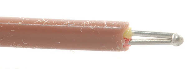
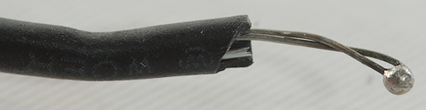
They consist of two wires that are usually welded together in the sensitive end. The other end is bare wires, banana plugs or special thermocoupler connectors. Precision depends on the exact alloys used, not on the thickness of the wires.
They output a very small voltage depending on the temperature difference between the connections. The connector at the other end will often affect precision.
The chip
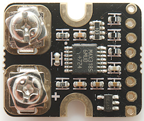

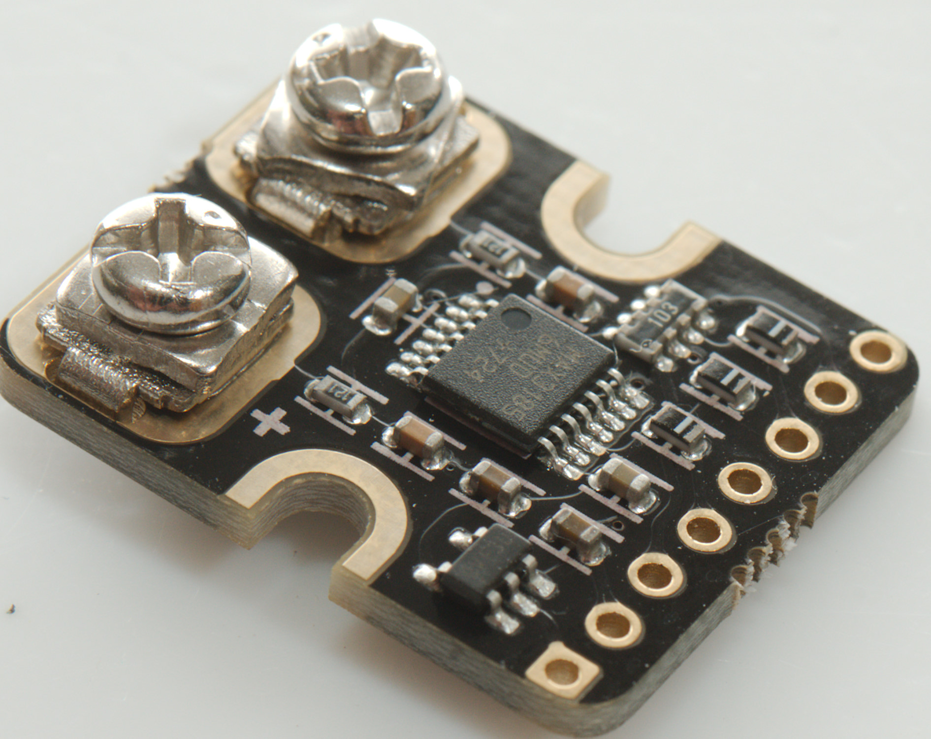
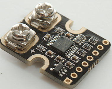
One module with the MAX31856, I uses this module because it has 5V conversion.
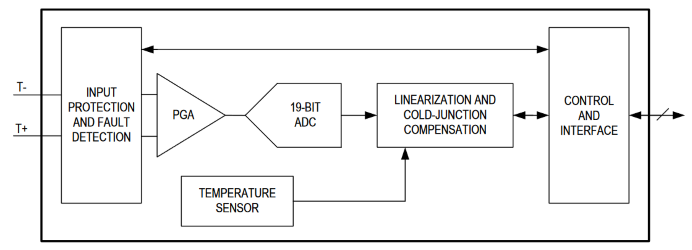
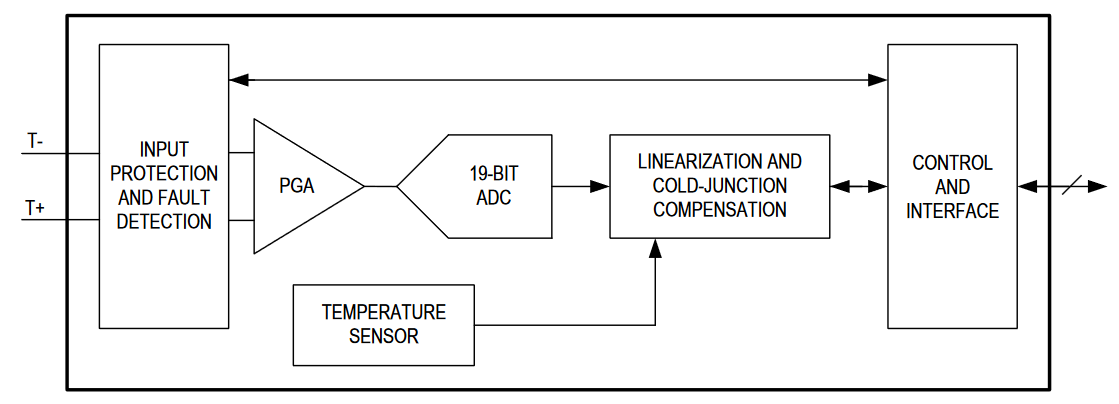
The chip basically has everything inside:
- Input protection, it can handle up to +/- 45V on the thermocoupler inputs.
- High resolution ADC, 19 bits resolution, this means considerable better than 0.1°C resolution.
- Cold junction compensation, a thermocoupler is relative, something is needed to compensate for ambient.
- Can also works as a uV/mV meter
- Alarm/error/out_of_range comparators, it is possible to get warning when temperate is outside a specified range.
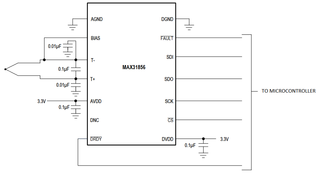
- Digital computer interface, it uses SPI interface.
- Uses 3.3V and requires 3.3V interface.
It looks good, except the 3.3V part may require some interfacing.
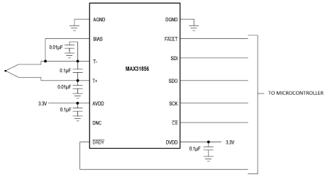
Very little support is needed for the chip, except maybe a 3.3V to 5V interface. It has two extra pins in addition to SPI interface, one is a FAULT pin and the other is a DRDY (Data ready) pin. The FAULT pin is available in software, both to configure and to read, but the data ready cannot be read from software, i.e. the chip do not have any software indication when a new value is available, not exactly user friendly when I want to limit the number of pins used.
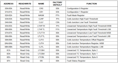
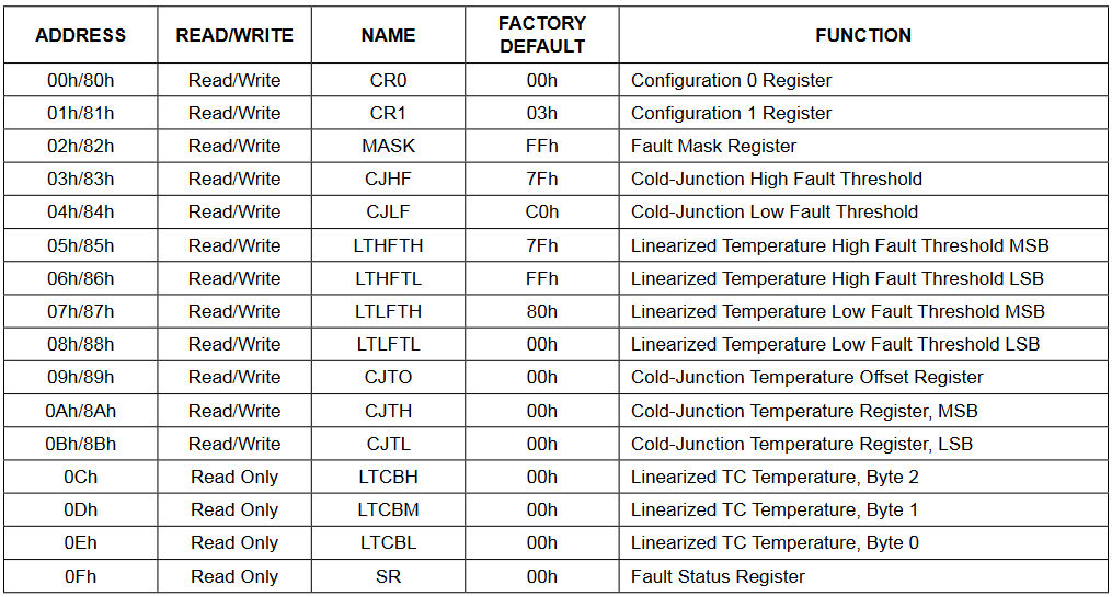
From software the chip is just a number of registers, some can both be read and written, other are read only. MPU SPI either transmit a address and one or more values or a transmit a address and read one or more values (Address defines if it is reading or writing).
Requirements
- Must work with only SPI interface without DRDY
- Allow use of multiple instances of library on same or different pins.
- Do not use the SPI library (It could be added later).
- Non blocking interface.
- Support most functions in the chip.
- Debug printout of registers
The library functions
Includes
Code:
#include <MAX31836.h>
Constants & types
These constants are matches values in the MAX31856 datasheet
- TC_FAULT_CJ_RANGE: Bitmask for cold junction range fault
- TC_FAULT_TC_RANGE: Bitmask for thermocoupler junction range fault
- TC_FAULT_CJ_HIGH: Bitmask for cold junction to high fault, this value is user definable.
- TC_FAULT_CJ_LOW: Bitmask for cold junction to low fault, this value is user definable.
- TC_FAULT_TC_HIGH: Bitmask for cold thermocoupler to high fault, this value is user definable.
- TC_FAULT_TC_LOW: Bitmask for cold thermocoupler to low fault, this value is user definable.
- TC_FAULT_VOLT: Voltage detected on thermocoupler input.
- TC_FAULT_OPEN: No thermocoupler detected on thermocoupler input.
These fault can be enabled/disabled (Except the _RANGE faults).
- TC_SAMPLES_1: Return each measured value, this is the fastest conversion.
- TC_SAMPLES_2: Average two measurement, this do not take double time.
- TC_SAMPLES_4: Average 4 measurements.
- TC_SAMPLES_8: Average 8 measurements.
- TC_SAMPLES_16: Average 16 measurements.
The chip can automatic do an average of multiple values.
MaxTCType
This chip support a couple of different thermocouplers and also directly reading voltage, these are defined as a enum:
TC_B, TC_E, TC_J, TC_K, TC_N, TC_R, TC_S, TC_T: Thermocoupler type from B E J K N R S T
TC_G8: Voltage mode with input amplifier at x8, this has a offset up to 16uV, in addition to any thermo voltage.
TC_G32: Voltage modes with input amplifier at x32, this has a offset up to 4uV, in addition to any thermo voltage.
For the two voltage modes I convert the output to millivolt, most faults can be ignored in these modes.
Note than the constant TC_G32 is not 1 higher than TC_G8, but takes a jump from ordinal value 8 to 12.
All functions
Constructor
Code:
MAX31856(byte sdiPin, byte sdoPin, byte sckPin, byte csPin);
MAX31856(byte sdiPin, byte sdoPin, byte sckPin, byte csPin, byte drdyPin);
The pin names are from MAX31856, this means sdiPin is the Arduino output pin and sdoPin is the Arduino input pin.
Except csPin and drdyPin all pins can be shared between multiple instances of this class.
When the drdyPin is used the thermocoupler must be read first, then the cold junction temperature.
Code:
#include <MAX31856.h>

#define SDIPIN 8
#define SCKPIN 9
#define SDOPIN 10
#define CSPIN 11

MAX31856 tc(SDIPIN, SDOPIN, SCKPIN, CSPIN);
With four wire connection and using millis() to time conversion
Code:
#include <MAX31856.h>

#define SDIPIN 8
#define SCKPIN 9
#define SDOPIN 10
#define CSPIN 11
#define DRDYPIN 12

MAX31856 tc(SDIPIN, SDOPIN, SCKPIN, CSPIN, DRDYPIN);
With five wire connection and using the data ready pin to see when a new value is ready.
Initialization
Code:
void begin();
void setTCType(MaxTCType type);
MaxTCType getTCType();
void setMainsFreq60Hz(boolean yes); // Use this before starting any conversions
inline boolean isVoltMode();
The begin() is placed in setup and will initialize the ports and MAX31856 and configure it for K type thermocouples and 50Hz mains frequency.
Use setTCType() and setMainsFreq60Hz() if required.
The setTCType() is also used to switch into volt mode (TC_G8 & TC_G32).
Use setMainsFreq60Hz() depending on the mains frequency, this will select the best filtering to get rid of mains noise.
The isVoltMode() will be true in x8 and x32 mode when output is in millivolt.
In x8 mode it is possible to measure from -35mV to 110mV
In x32 mode it is possible to measure from -8.8mV to 27mV
The input voltage cannot be referenced to GND on the MAX or Arduino, but must be floating.
Code:
#include <MAX31856.h>

#define SDIPIN 8
#define SCKPIN 9
#define SDOPIN 10
#define CSPIN 11

MAX31856 tc(SDIPIN, SDOPIN, SCKPIN, CSPIN);

void setup() {
  tc.begin();
  tc.setTCType(TC_K);
  tc.setMainsFreq60Hz(false);
}
Thermocoupler
Code:
void setAuto();
boolean isAuto();
float readTCTemp();
void start();
boolean isReady();
This conversion can either run continuous or on demand.
In auto mode, that is the default or can be started with setAuto() the converter will start a new conversion when the last one is finished, using readTCTemp() will always return the latest converted temperature. When drdyPin is used readTCTemp() will wait for next conversion. isReady() will reflect the state of the drdyPin.
With drdyPin connected readTCTemp() must be used before readCJTemp() to get best performance.
Using start() will switch to on-demand conversion and start a new conversion. The isReady() function will be false until enough time has passed or drdyPin goes low for the conversion to be done. Calling readTCTemp() will stall until isReady().
Code:
#include <MAX31856.h>

#define SDIPIN 8
#define SCKPIN 9
#define SDOPIN 10
#define CSPIN 11

MAX31856 tc(SDIPIN, SDOPIN, SCKPIN, CSPIN);

void setup() {
  Serial.begin(9600);
  tc.begin();
  tc.start();
}

void loop() {
  if (tc.isReady()) {
    Serial.print("Temperature is: ");
    Serial.print(tc.readTCTemp());
    Serial.println("*C");
    tc.start();
  }
}
Without drdy connected
Code:
#include <MAX31856.h>

#define SDIPIN 8
#define SCKPIN 9
#define SDOPIN 10
#define CSPIN 11
#define DRDYPIN 12

MAX31856 tc(SDIPIN, SDOPIN, SCKPIN, CSPIN, DRDYPIN);

void setup() {
  Serial.begin(9600);
  tc.begin();
  tc.setSamples(TC_SAMPLES_16);
  tc.setAuto();
}

void loop() {
  if (tc.isReady()) {
    Serial.print("Temperature is: ");
    Serial.print(tc.readTCTemp());
    Serial.println("*C");
  }
}
With drdy pin connected and using 16 samples for each reading
Code:
#include <MAX31856.h>

#define SDIPIN 8
#define SCKPIN 9
#define SDOPIN 10
#define CSPIN 11

MAX31856 tc(SDIPIN, SDOPIN, SCKPIN, CSPIN);

void setup() {
  Serial.begin(9600);
  tc.begin();
  tc.setSamples(TC_SAMPLES_16);
  tc.setTCType(TC_G8);
  tc.start();
}

void loop() {
  if (tc.isReady()) {
    Serial.print("Input voltage is: ");
    Serial.print(tc.readTCTemp(),3);
    Serial.println("mV");
    tc.start();
  }
}
Measuring millivolt without drdy connected, range is from -35mV to 110mV
Cold junction
Code:
float readCJTemp();
void setCJOffset(float ofs);
float getCJOffset();
void setCJTemp(float temp);
void setCJAuto(boolean yes = true);
boolean isCJAuto();
A thermocoupler gives relative temperature to its connector. The chip has a internal temperature sensor that is used to get absolute temperature, for this to work the chip must have the same temperature as the connector or connection. This temperature is called the cold junction, in the library I uses CJ for it.
To read the CJ temperature use readCJTemp(), the actual conversion will be done at the same time the thermocoupler temperature is converted, this means that this will only be updated when doing thermocoupler conversions. It is possible to "calibrate" this temperature with setCJOffset(), this will change both the CJ and thermocoupler temperature.
In cases where the cold junction is far from the chip it is possible to use an external temperature sensor and specify the CJ temperature with setCJTemp(), this will disable converting the internal thermocoupler, use setCJAuto() to enable the internal sensor again. It is also possible to do setCJAuto(false) to freeze the current internal temperature reading.
Code:
#include <MAX31856.h>

#define SDIPIN 8
#define SCKPIN 9
#define SDOPIN 10
#define CSPIN 11

MAX31856 tc(SDIPIN, SDOPIN, SCKPIN, CSPIN);

void setup() {
  Serial.begin(9600);
  tc.begin();
  tc.setCJOffset(-0.2);// Apply a small correct to the internal temperature
  tc.setCJAuto();// Start automatic conversion
}

void loop() {
  Serial.print("Internal chip temperature is: ");
  Serial.print(tc.readCJTemp());
  Serial.print("*C inclusive a ");
  Serial.print(tc.readCJOffet());
  Serial.println("*C icorrection");
  delay(1000);
}
Averaging result
Code:
    void setSamples(byte n);
    byte getSamples();
    uint16_t sampleTime();
The chip can average up to 16 samples, but only with a few specified values: 1, 2, 4, 8, 16 and n is the index from this list. To specify the number of samples it is easiest to use the TC_SAMPLES_n constants. The value from getSamples() is the same constants.
When doing more samples the conversion time will be longer, the sampleTime() function will return the maximum conversion time for the current selection, this time is based on on-demand mode and 50Hz mains frequency. In auto mode the sample time is considerable shorter, but once in a while there will be a slow conversion.
Code:
#include <MAX31856.h>

#define SDIPIN 8
#define SCKPIN 9
#define SDOPIN 10
#define CSPIN 11

MAX31856 tc(SDIPIN, SDOPIN, SCKPIN, CSPIN);

void setup() {
  Serial.begin(9600);
  tc.begin();
  tc.setSamples(TC_SAMPLES_4);
  Serial.print("Maximum sample time: ");
  Serial.print(tc.sampleTime());
  Serial.println("ms");
}

void loop() {
}
Specify that each reading must be an average of four samples. Using sampleTime() it can be seen this will take up to 310ms
Alarms and warnings
Code:
byte getFault();
void setFaultMask(byte mask);
void setCJRange(int8_t low, int8_t high);
int8_t readCJRangeLow();
int8_t readCJRangeHigh();
void setTCRange(float low, float high);
float readTCRangeLow();
float readTCRangeHigh();
There is 8 different fault/alarm/error conditions (They are all called fault), these are defined by the TC_FAULT_xxx constants. They can be read by the readFault() function, if they are enabled. The faults will also turn on the fault output pin, that is often used for a red led.
Except the RANGE faults they can be enabled/disabled with the setFaultMask() function, a included value will be disabled.
The HIGH/LOW faults are custom defined and is done with the setCJRange() & setTCRange for cold junction and thermocoupler, the resolution is lower on these than the temperature reading. The chip do also have some hysteresis build in.
The defined values can be read with the four read... functions.
All these faults will only activate after doing a conversion, i.e. either the chip must be in automatic conversion mode or it must be started at regular intervals to detect faults.
Code:
#include <MAX31856.h>

#define SDIPIN 8
#define SCKPIN 9
#define SDOPIN 10
#define CSPIN 11

MAX31856 tc(SDIPIN, SDOPIN, SCKPIN, CSPIN);

void setup() {
  Serial.begin(9600);
  tc.begin();
  tc.setTCRange(20.0, 35.0);// Set temperature limits
  tc.setAuto();// Start automatic conversion
}

void loop() {
  byte fault = tc.getFault();
  if (fault & TC_FAULT_TC_HIGH) Serial.println("Temperature too high");
  if (fault & TC_FAULT_TC_LOW) Serial.println("Temperature too low");
  if (fault & TC_FAULT_OPEN) Serial.println("Thermocoupler not connected");
  if (fault & TC_FAULT_VOLT) Serial.println("Voltage detected on thermocoupler input");
  delay(1000);
}
Debug
Code:
void serialPrintAllRegisters();
For debugging or modifying the code this function can be used to get an idea about the current status of the MAX31856. It requires the datasheet for the chip to use all the data.
Connection Arduino and MAX31856 module
The actual data connections may be easy enough, because any digital and most analog pins on a Arduino can be used, but because the chip is 3.3V it is importance to check if the module has support/conversion for 5V or uses a 3.3V Arduino.
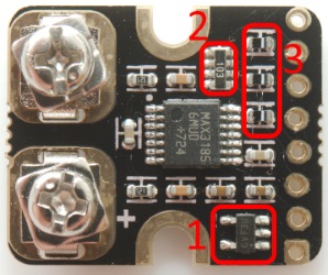
On this board there is a voltage regulator (1) to convert 5V supply to 3V supply. For the datalines there is diodes (3) and resistors (2).
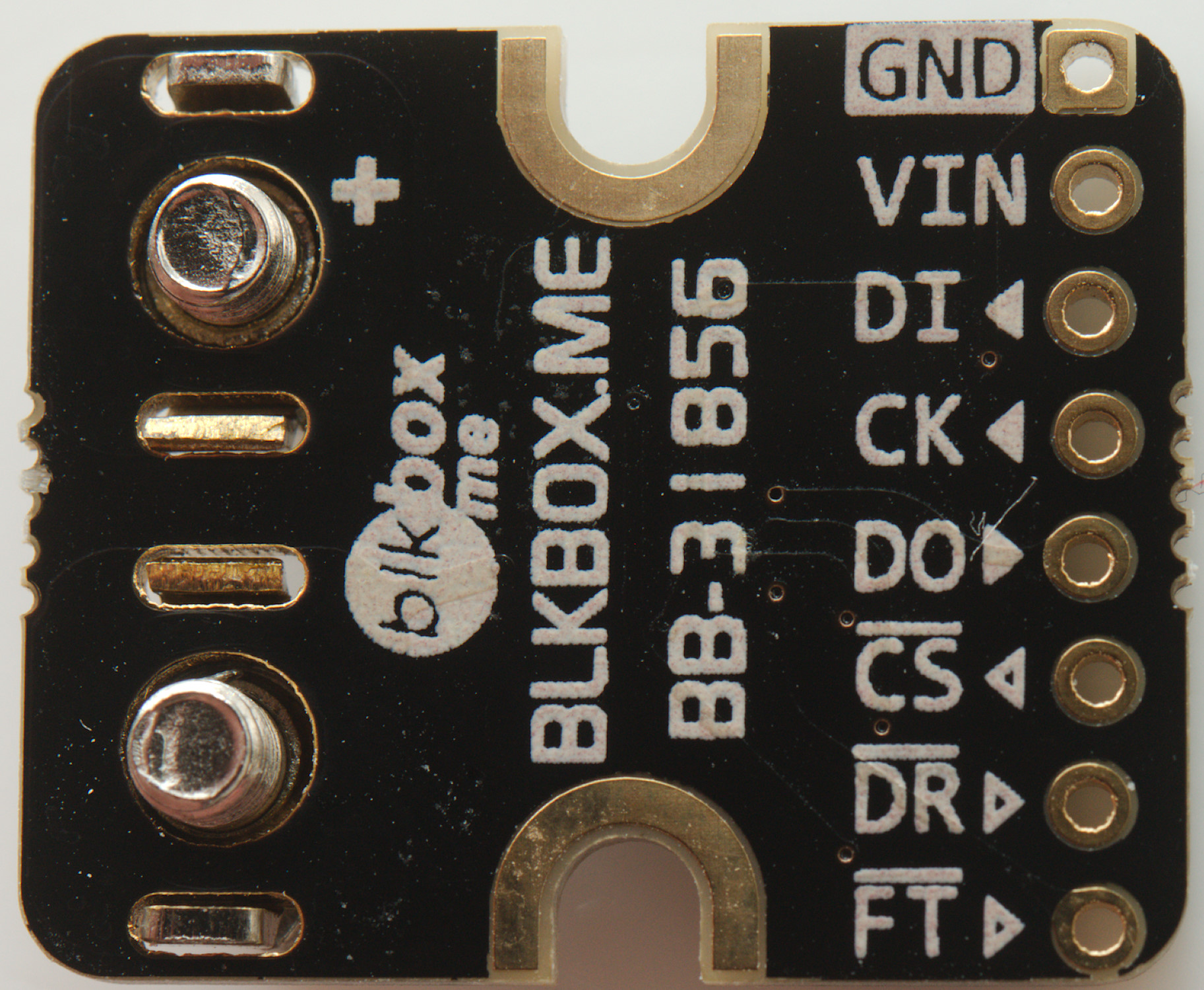
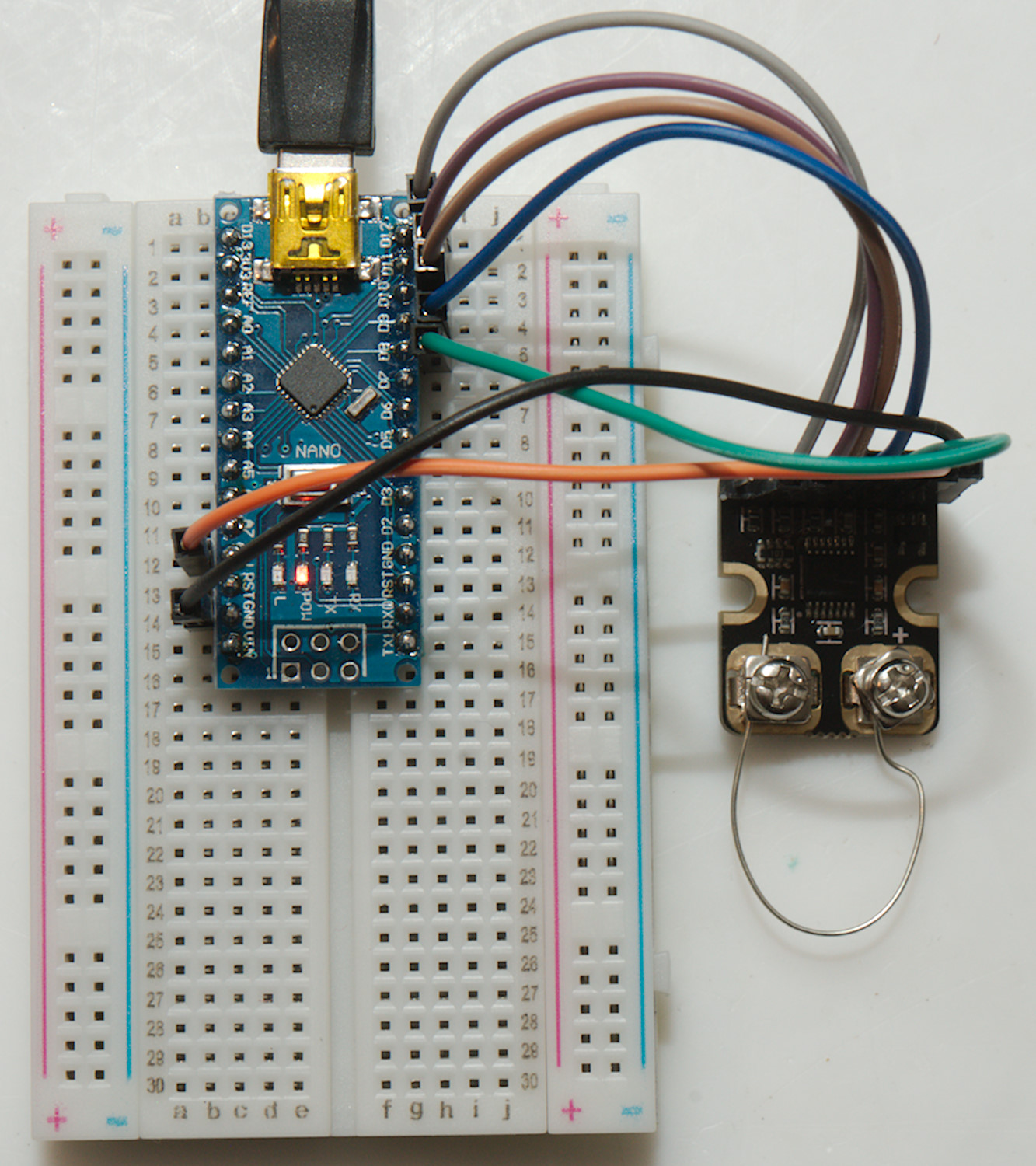
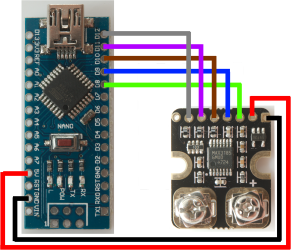
Connect DI->sdiPin, DO->sdoPin, CK->sckPin, CS->csPin, DR->drdyPin (optionally), GND->0V, VIN->5V, the last pin is not used.
Using the drdyPin allows faster conversions (400ms-500ms for 16 sample conversion) while reading each sample once using auto mode. Without drdyPin it is best to use on-demand mode, this means slower conversions (900ms for 16 sample conversion)
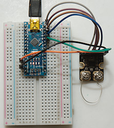
My test setup, here I am using a piece of wire instead of a thermocoupler.
Conclusion
The library makes it easy to use just about any function in the chip and can work both with and without the DRDY connection.
It is possible to use multiple instances of the library to handle multiple thermocouplers, this means a Nano with 18 IO pins (Serial excluded) can handle 7 thermocouplers with drdy or 15 without drdy.
The library includes a couple of simple examples, some similar to the code shown here.
Notes and software download
MAX31856 library