Making Arduino timing more precise
I often see people want a RTC connected to their Arduino to get more precise time, but that is not always necessary. Here I will look at how precise the Arduino is and how to get the best possible time precision.
Contents
Making Arduino timing more precise
Specifying time precision
What is a RTC and where to use it
What is a RTC
Where to use it
Examples on RTC chips
How to calibrate the time on Arduino
Crystals
How to apply adjustment
How to measure amount of adjustment to apply
Is the Arduino time now precise?
Software
The library (PrecisionTime)
Using the library
Interrupt handler and second counter
Interrupt configuration and routine
Clock with seconds, minutes, hours, date, month, year
PC calibration interface
Checking for calibration
The Arduino sketch
PC program
Testing RTC's
Supported processors
Arduino UNO (Mega328)
Arduino Mega (Mega2560)
Arduino Nano (Mega168 & Mega328)
Seeeduino Nano (Mega328)
ProMicro simulating Arduino Leonardo (Mega32U4)
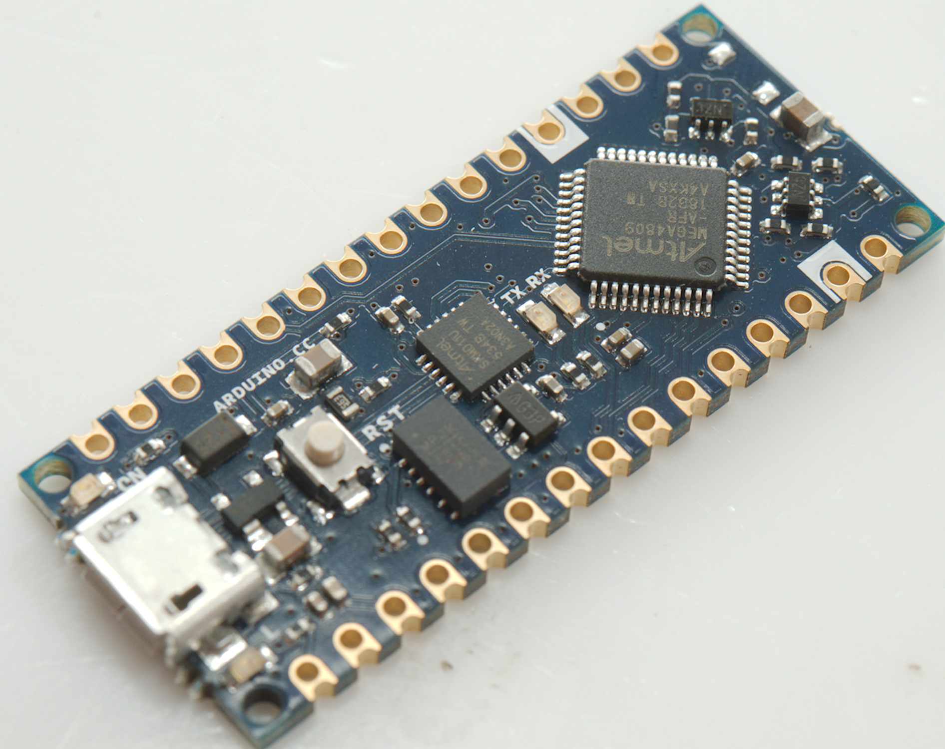
Nano Every (ATMega4809)
Other
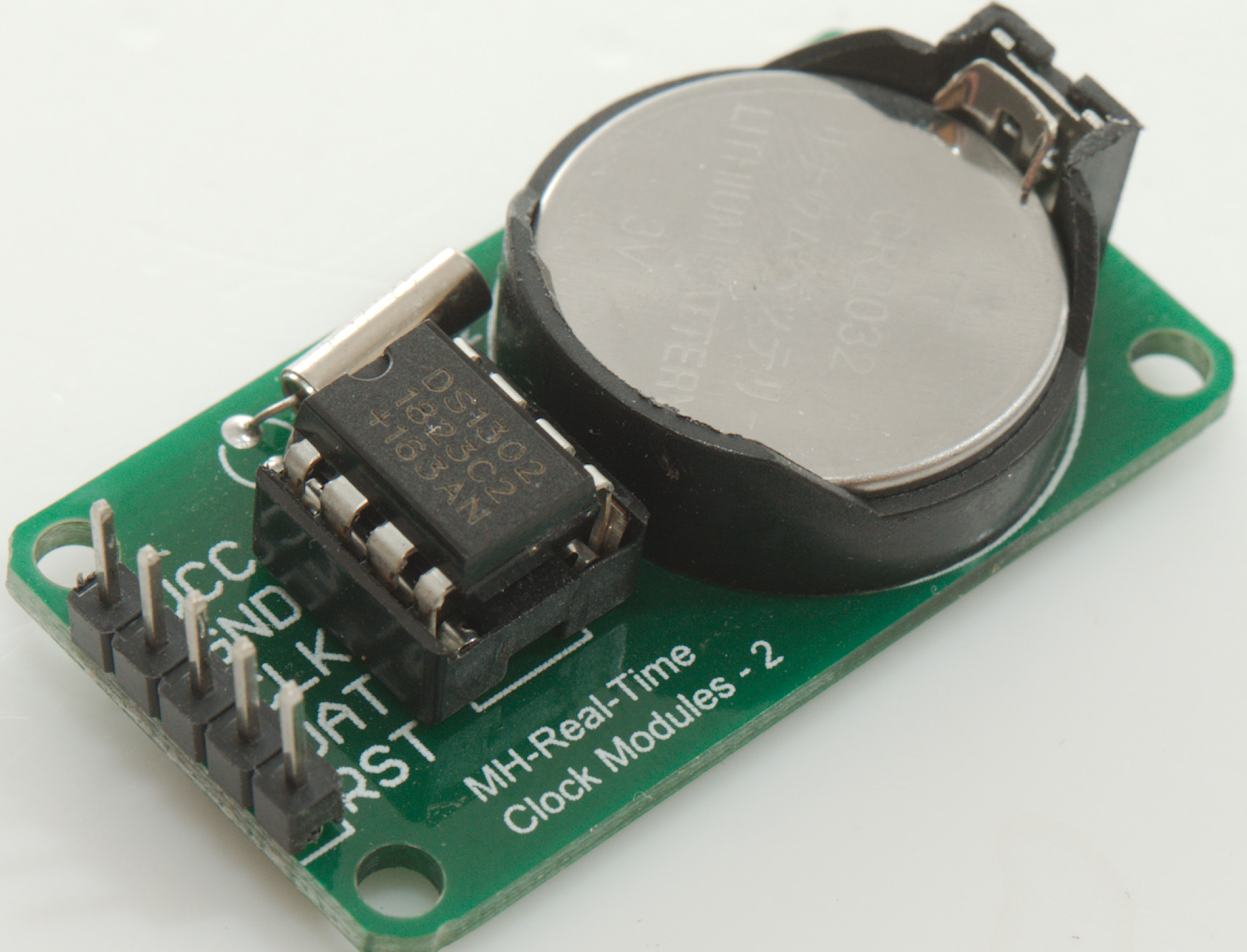
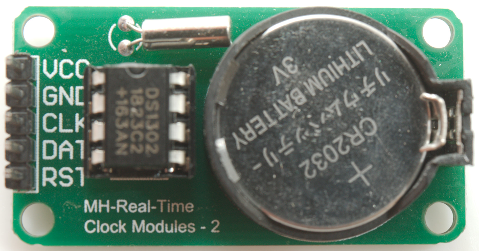
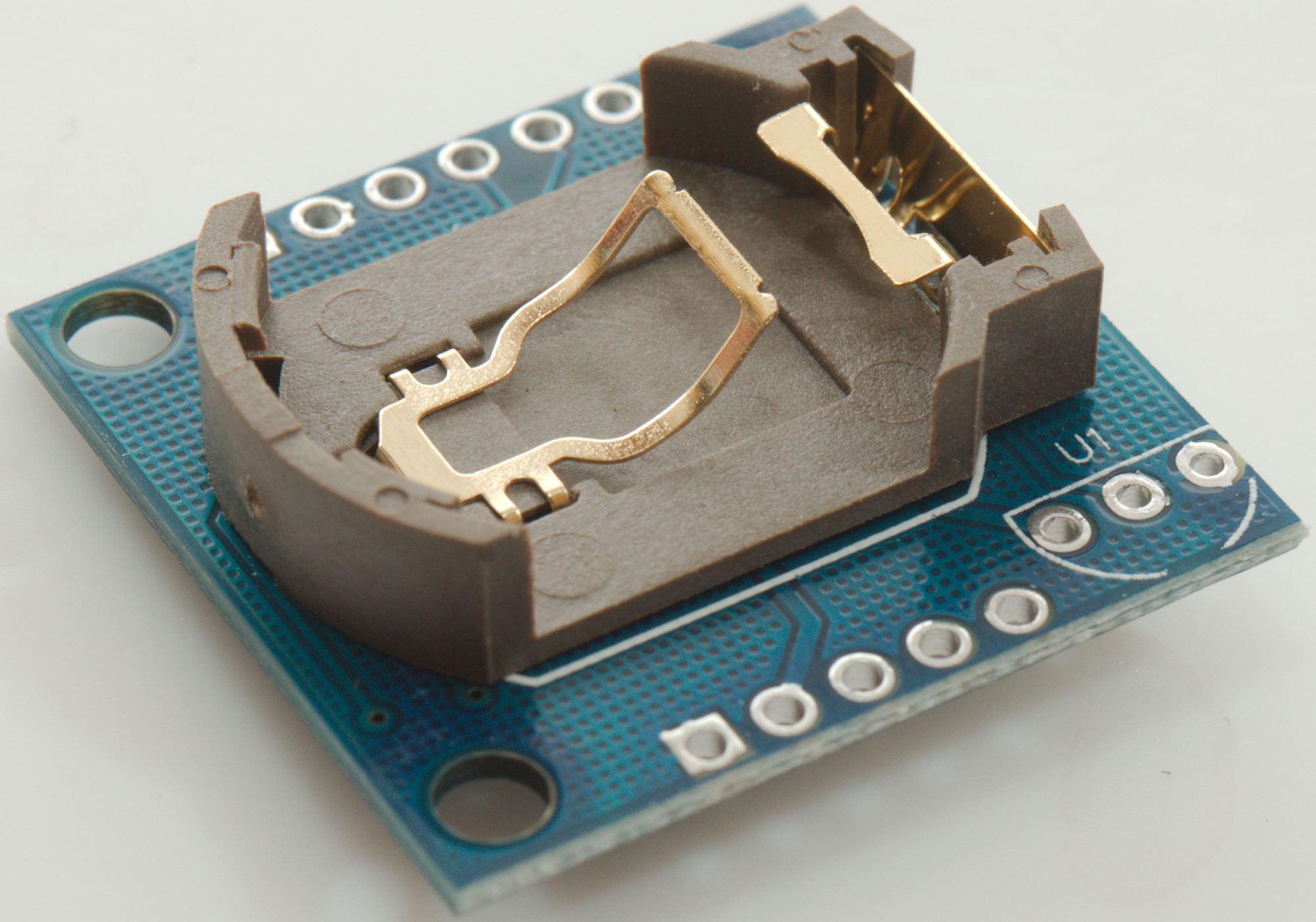
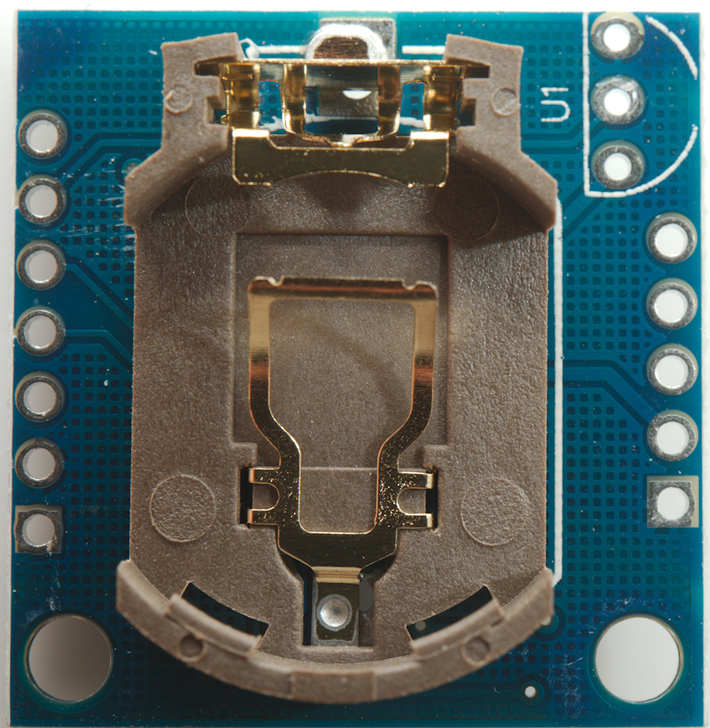
Tested RTC's
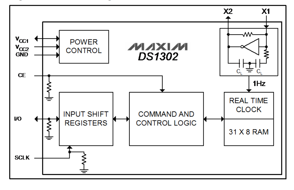
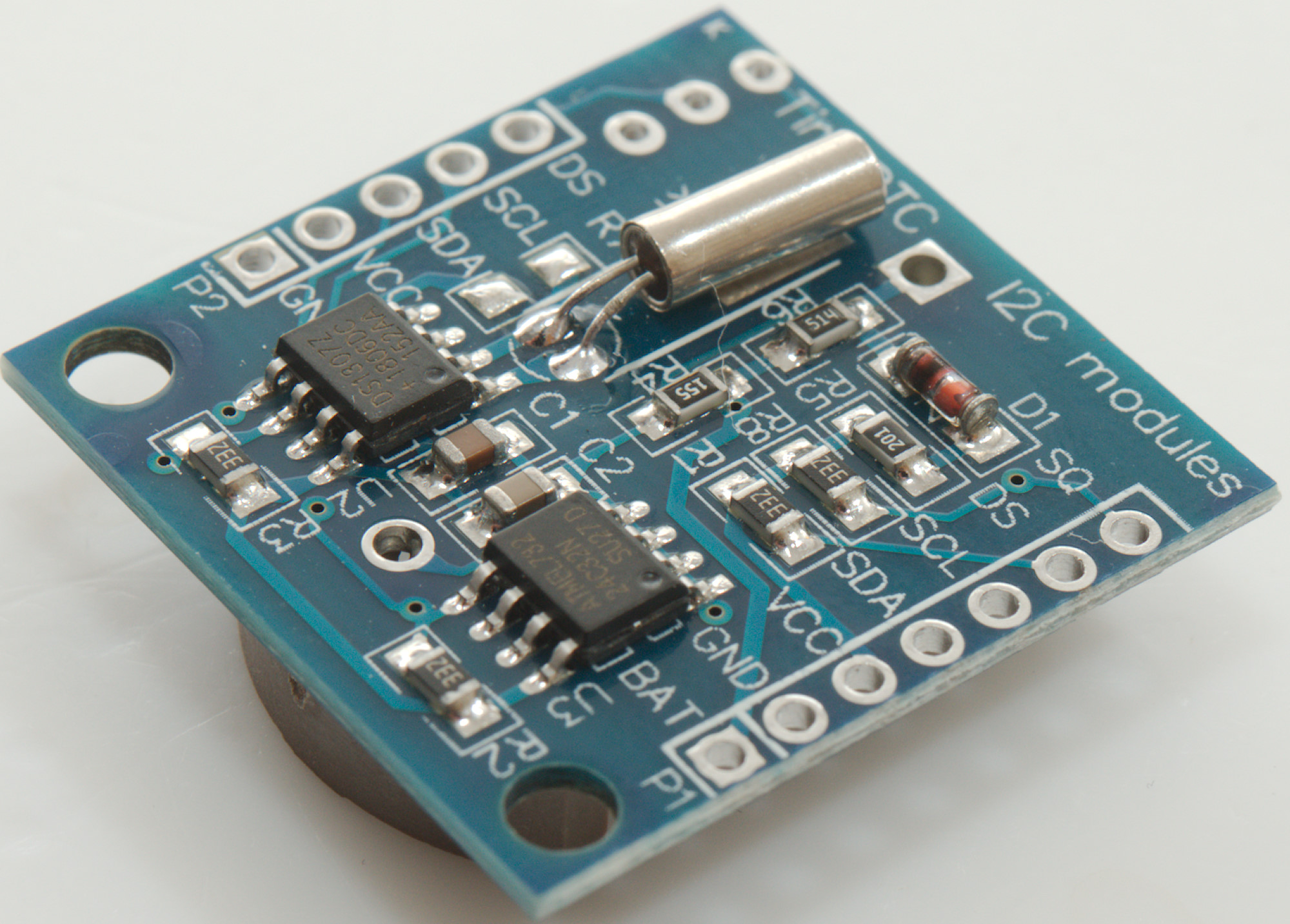
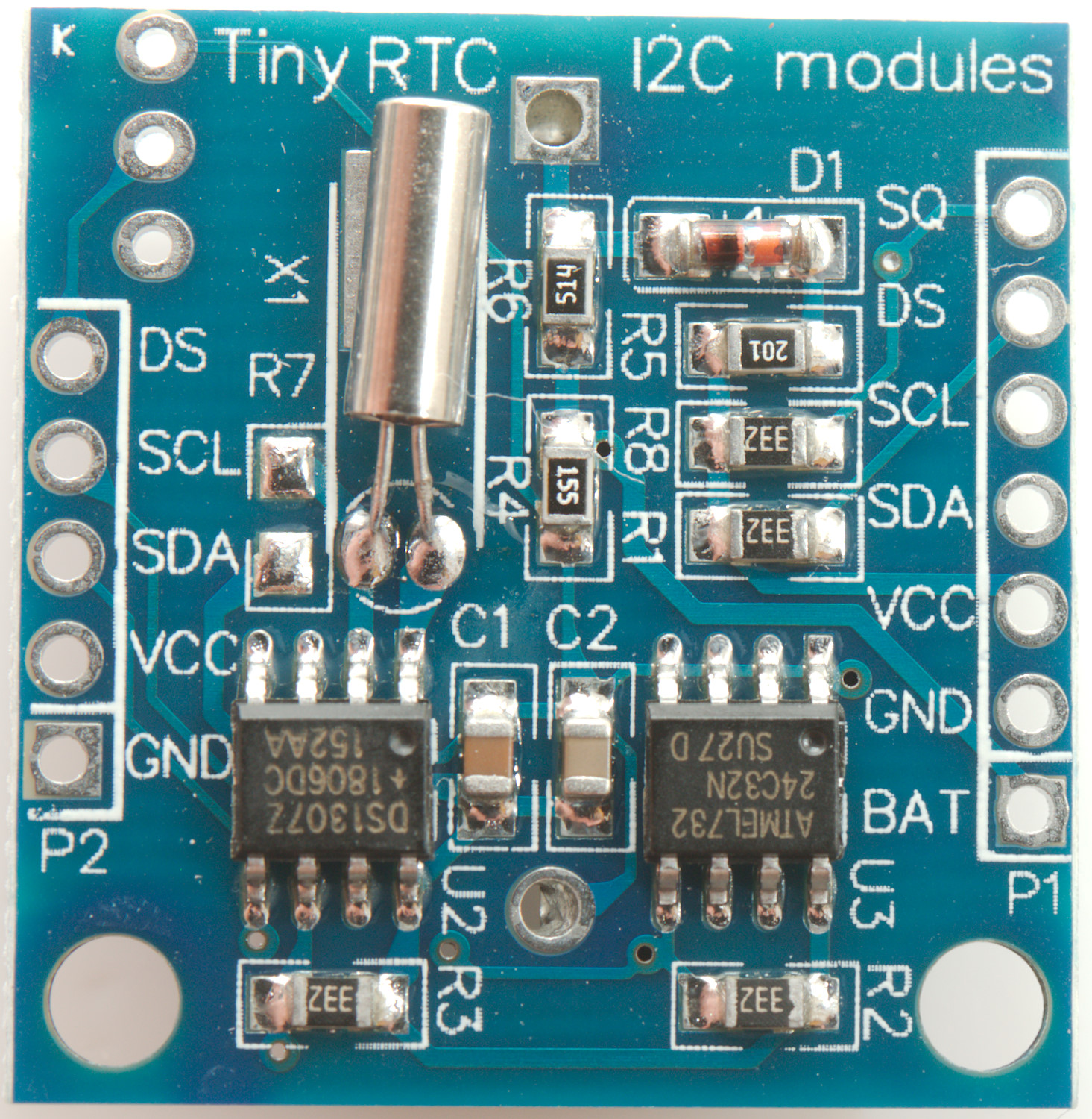
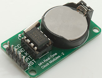
DS1302
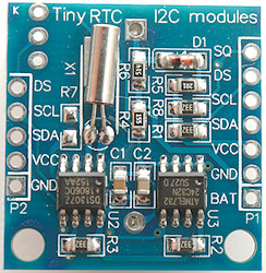
DS1307
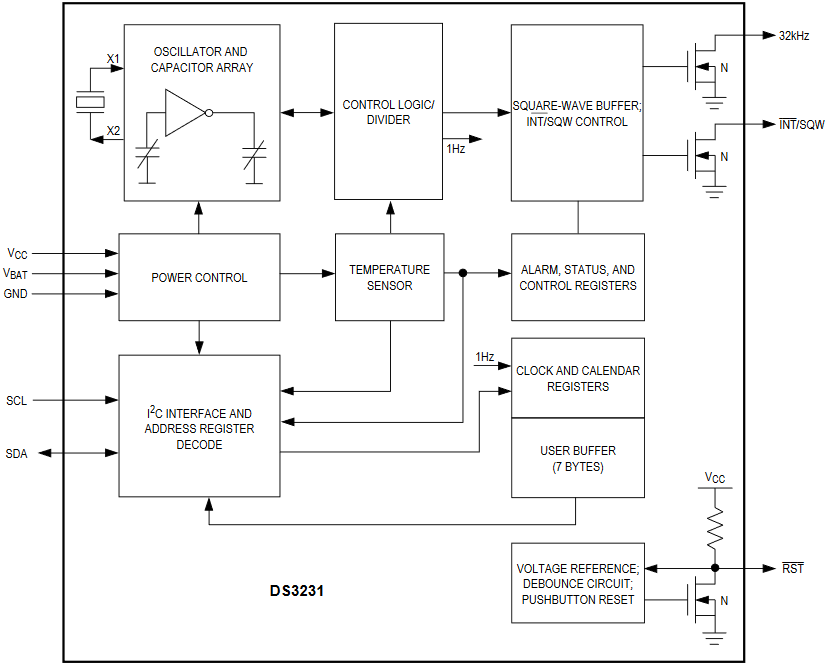
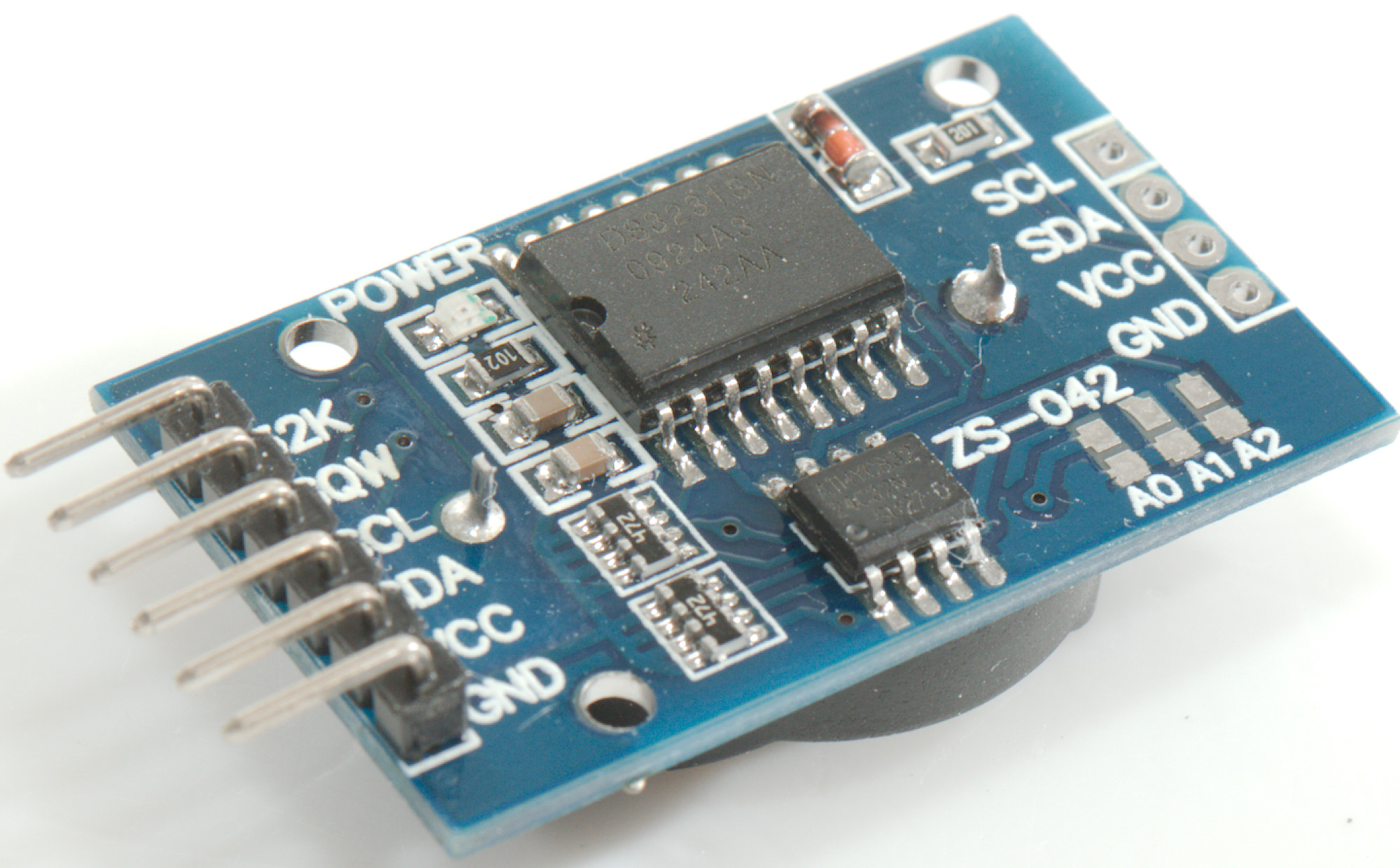
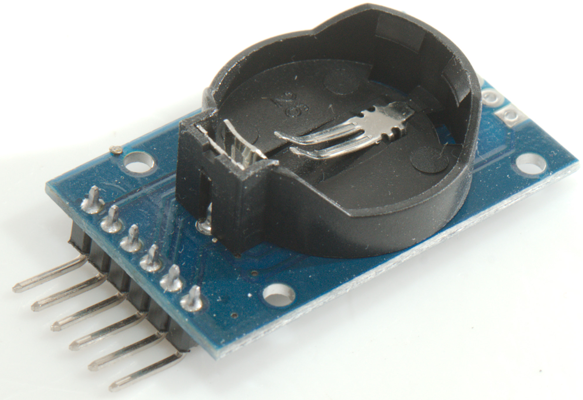
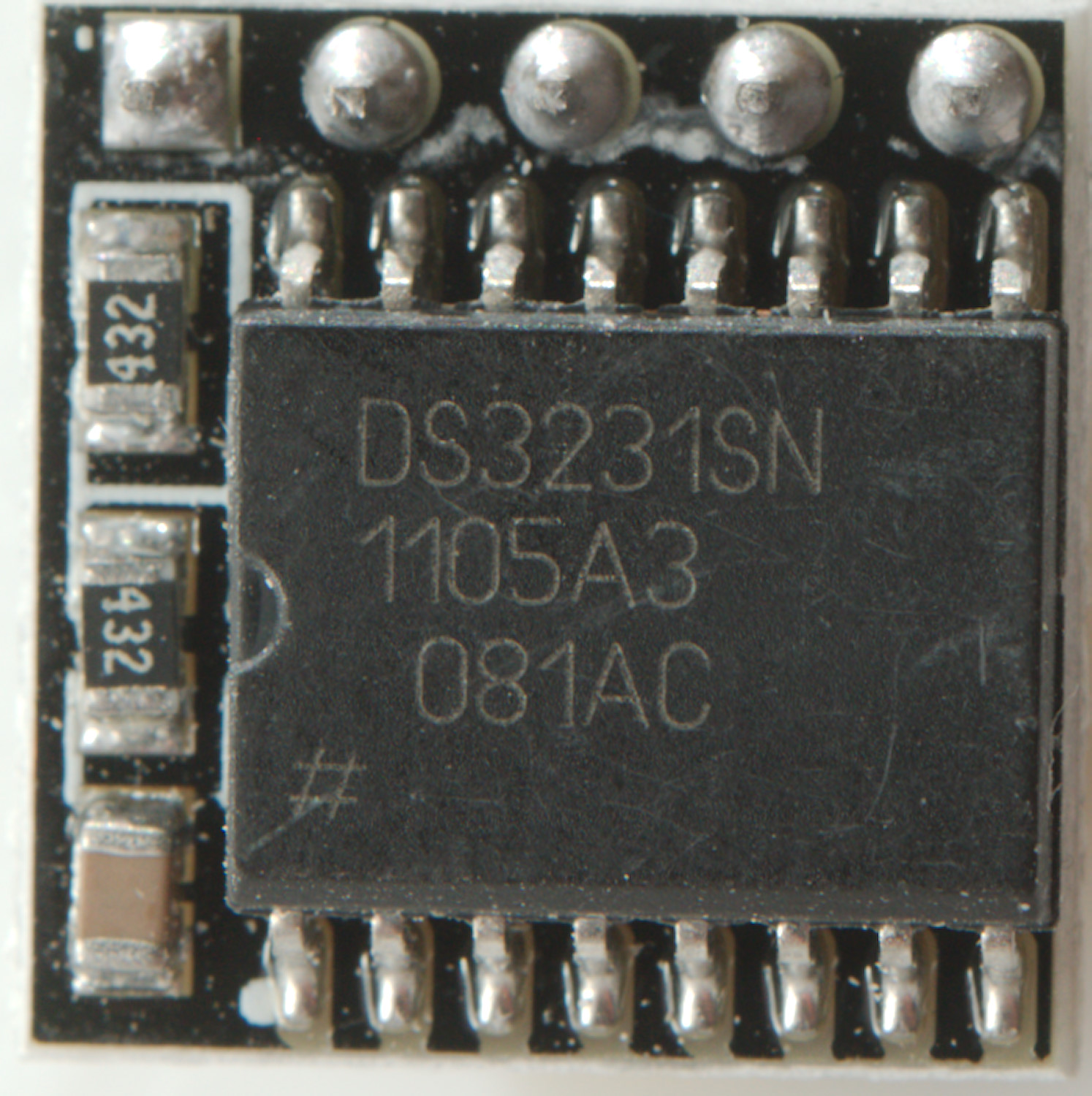
DS3231
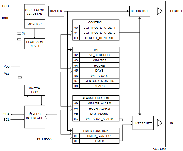
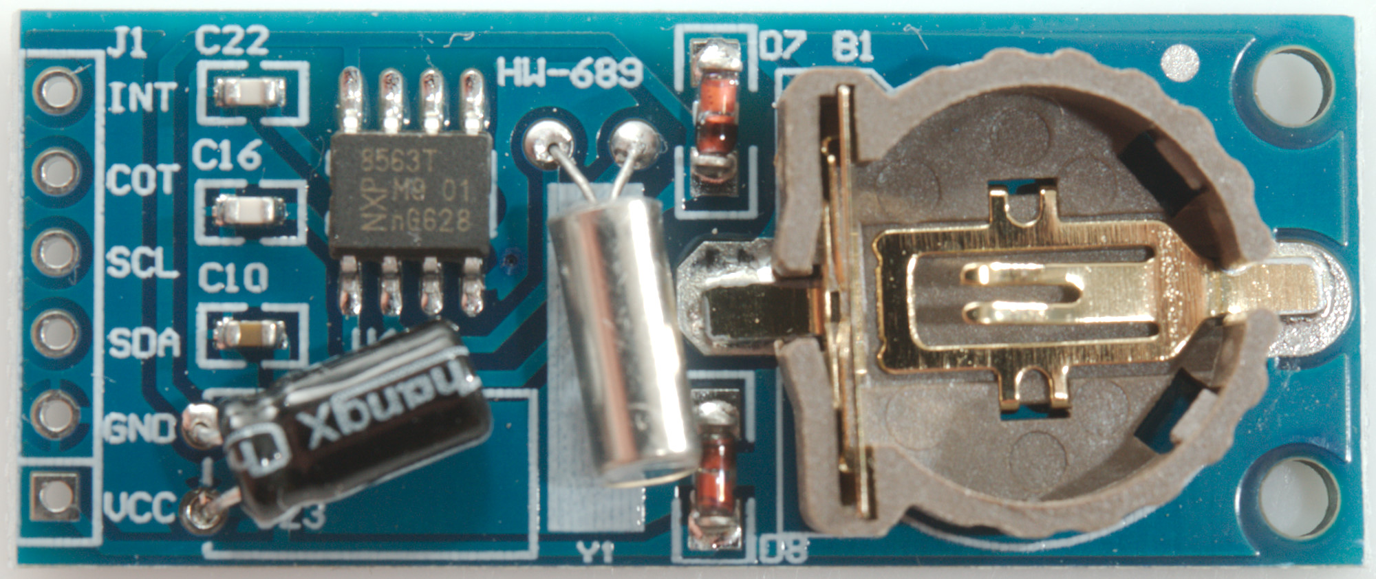
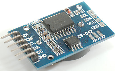
PCF8563
Conclusion
Notes and download
Specifying time precision
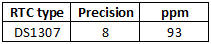
How good precision can be expected?
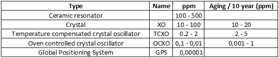
The above table shows some of the different technologies used to get a stable frequency or time. The data are a rough specification for that type of technology, there will be both better and worse devices around.
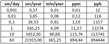
Here are some of the values used to specify time precision with a conversion between them.
What is a RTC and where to use it
Lets first look at what a RTC (Real Time Clock) is and in what applications a RTC is necessary.
What is a RTC
A typical RTC consist of a chip, a battery and a tiny 32768Hz crystal. The 32768Hz crystal is a typical watch crystal, i.e. it is used in many different types of electronic clocks, there are two reasons for the frequency:
- It is fairly low, this means low power consumption.
- Divide 15 times with two and you got 1 pulse every second (Divide by two is the simplest divider to make).
The chip will count seconds and organise the result in seconds, minutes, hours, days, months and years. Because the chip is battery backed it will often have a small amount of extra non volatile ram that can be used by a microprocessor.
Where to use it
With a battery, low power consumption and independent operation it is perfect for keeping time when a device has other stuff to do and in some cases it may improve the precision. In the Arduino world this translates to:
1) Low power, Arduino needs to sleep.
2) Reset, Arduino is reset when connected to a PC
3) Workload, Arduino is doing too much and can not spare the resources to keep precise time.
4) Blocking tasks, the program needs to disable/ignore interrupts for some time.
5) You Arduino has a ceramic resonator and it varies too much
6) You Arduino uses a internal RC oscillator, this is worse than a ceramic resonator.
7) High precision clock, a advanced RTC chip may have special circuit to make the oscillator more stable.
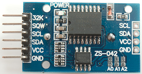
Examples on RTC chips
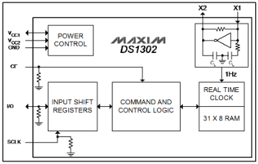
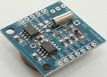
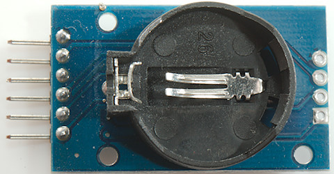
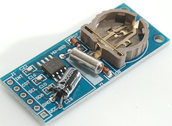
DS1302: This is a simple RTC chip with the crystal, input for battery and normal power, option to charge battery, date and time registers and a few bytes spare ram.
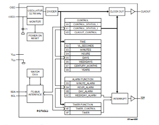
PCF8563: Another simple RTC chip with one alarm (Can be used to bring a processor out of sleep), but only a single power input (Combining battery and normal power must be done externally), no battery charging supported.
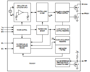
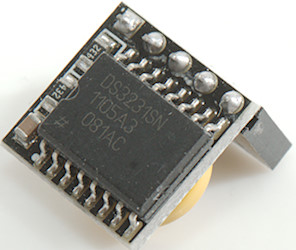
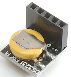
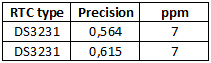
DS3231: This chip is more advanced and also have two alarms (Can be used to bring a processor out of sleep). It has temperature and age compensation of the oscillator (This makes it a TCXO), this is possible because the crystal is build into the chip. Specified to be within 2 minutes a year.
How to calibrate the time on Arduino
The Arduino often use a cheap crystal or ceramic resonator and is not calibrated, due to this the clock frequency will usually be a bit beside the 16000000 ticks a second (16MHz clock), but it will be fairly stable. This means that adding or subtracting some time at regular intervals will make the time more precise. There is a few challenges with this:
- A specific time may occur twice or never, i.e. just before adding/subtracting and just after.
- How do we get this calibrated?
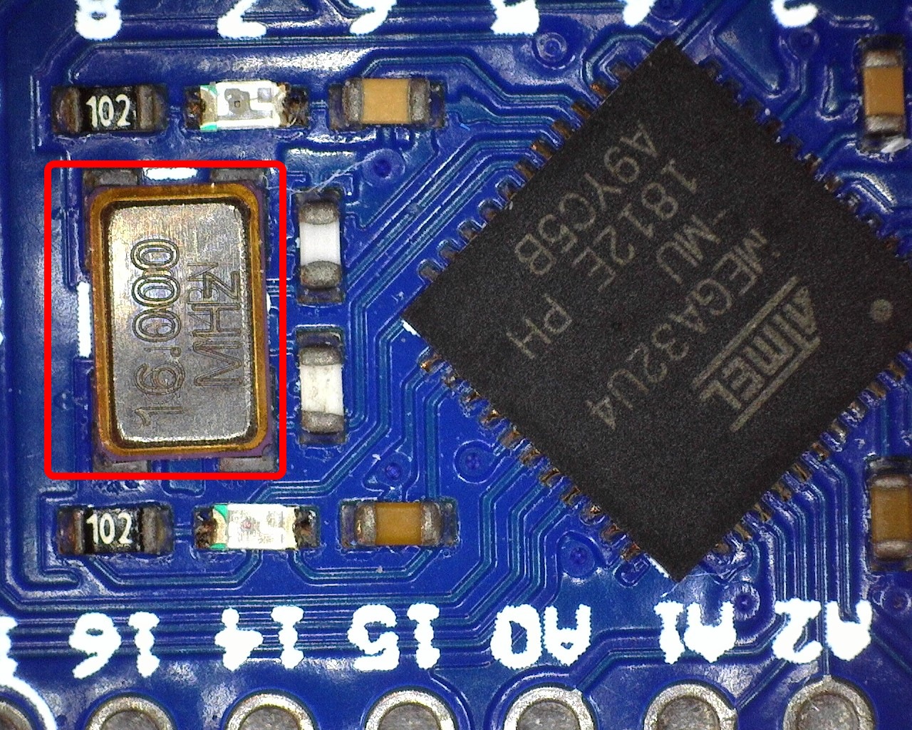
Crystals

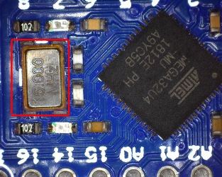
Two "crystals" from Arduino processors. The first one is probably a ceramic resonator (they work the same ways as crystal, but are cheaper). See chapter about Arduino boards for more examples.
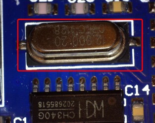
On UNO, Mega and some other there is a extra crystal, it is usual marked 12MHz. This is not for the Arduino processor, but for the USB interface and must be precise enough for that.
How to apply adjustment
The usual way to make a timer is to use a hardware time and have a interrupt to count at specific interval. Lets say every millisecond, 16000000Hz (Arduino crystal) to 1000Hz is possible on a Arduino hardware timer. When the counter reach 1000 a second is passed and the second register can be incremented. If we increment the second register when reaching 999 instead of 1000 the seconds will run 0.1% faster, we could also count to 1001 for 0.1% slower. Only problem with this is the 0.1% resolution, it is not very precise, more exactly it is 86.4 seconds in a day. What if we add 10 to the counter register each millisecond and when it reaches 10000 we subtract 10000, this will give exactly the same speed, but subtracting 9999 or 10001 is 0.01% or 8.64 second a day, this is much better. In my solution I do not use a 1000 or 10000 counter, but a 8640000 counter, i.e. interrupt adds 8640, this may look like a strange number, but is very practical to calculate on because there is 86400 seconds in a day and by adding two extra zeros each time I add or subtract one it will be 0.01 second a day.
This means if I measure the Arduino looses 15.32 seconds a day, I simply subtracts 8640000-1532-> 8638468 from the counter each second instead of 8640000 and the seconds will count correctly.
The interrupt do not have to be 1000 times a second, but using it means the length of a second will be adjusted in 1/1000 of a second steps when correcting.
How to measure amount of adjustment to apply
If there is a human in the measurement loop there will be a tolerance of 0.3 second to a couple of seconds depending on the user interface, this means the calibration time must take a couple of days to get precision around a second a day, this is not very practical.
Instead I connect the Arduino to a PC and let the PC measure, there I can get around 0.005 second tolerance, this means a 15 minute calibration time is enough to get a fairly good calibration (Within one second a day), longer time will give a better calibration.
But how to do it, on the Arduino I work in seconds and if I just read the seconds I will have a tolerance of a full second? The idea is to look for a change, i.e. read the second values multiple times until it change, then store it together with the PC's millisecond value (That is fairly precise). Doing it again some time later and I can calculate the speed of the Arduino with 1 millisecond resolution for that time interval.
With that it is fairly easy to calculate time error in a day and use it as a correction factor to the 8640000 from above.
To get best possible precision the millis interrupt is disabled during calibration.
Is the Arduino time now precise?
The answer is no, firstly it is calibrated to the PC clock and that is not perfect. On the Arduino the oscillator will have variation based on:
- Clock generator: Crystals are better than ceramic resonators, that are better than (internal) RC oscillators.
- Temperature, keeping the Arduino at a constant temperature will give best precision.
- Voltage, using stabilized power for the Arduino is best, i.e. feed 8V into the Vin pin is better than USB supply.
- Electric noise, keep the Arduino away from motors, power switches, radio transmitters etc.
- Age, crystals will change with age.
The above list applies both to RTC modules and to the crystal on the Arduino.
It is not possible to fix all the above factors, but minimizing them will improve the precision and remember to do the calibration at the actual voltage and temperature the Arduino is used at for best result. Use a Arduino with a crystal for best results.
Also remember that the Arduino is calibrate to the same clock speed as the PC, i.e. it will not be better than the PC clock.
Software
The software is in 3 parts, a Arduino library, a Arduino sketch and a PC program.
The library (PrecisionTime)
The library is called PrecisionTime and has a couple of different parts, it is not requires to use all of them. The compile will remove the unused part, this means less flash memory requirement. The parts are:
- Interrupt handler and second counter
- Interrupt configuration and vector to handler.
- Clock with seconds, minutes, hours, date, month, year
- PC calibration interface
Only the first is mandatory to include in your programs. The second can be included or you can make your own.
Using the library
Code:
#include "PrecisionTime.h"

PrecisionTime precisionTime(PRECISIONTIME_EEPROM_ADDRESS);

PRECISION_TIMER_INTR(precisionTime)
The library is simple to use, include it, instantiate it, the parameter is where in the EEPROM it saves the calibration factor, you can use the supplied constant or supply your own address. Last add a interrupt handler.
Interrupt handler and second counter
This is the mandatory part, that must be called 1000 times each second, it will apply the adjustment and count seconds.
Code:
byte getDeltaSeconds();
This routine returns how many seconds since it was last called, this is the correct time. There is two ways to use this:
Code:
void loop() {
  ...
  precisionTime.update();
  ...
}
Either call the update function in the main program loop to maintain a seconds, minutes, hours, ... counter
Code:
void loop() {
  ...
  mySecondCounter+=precisionTime.getDeltaSeconds();
  ...
}
Or maintain your own second counter.
The function returns a byte sized answer, this means it must be called at least once every 4 minutes or it will loose time.
This function must be called 1000 times each second, if the interrupt part is included this is handled by the library. Without the interrupt part included you must supply your own interrupt and call this routine 1000 times a second. If it is called slightly faster or slower it will still be possible to calibrate it.
Interrupt configuration and routine
The interrupts do not require any coding, but there must be a call to the interrupt handler in your code.
Code:
PRECISION_TIMER_INTR(precisionTime)
This is done with this define, it must be placed outside any function.
The library support from timer1 to timer5 on Arduino and must have exclusive use of that timer. The default is to use timer1
Code:
//#define _USE_TIMER0_   // Supported on Mega4809(B0)
#define _USE_TIMER1_   // Supported on Mega328 & Mega2560 & Mega32U4 & Mega4809(B1)
//#define _USE_TIMER2_   // Supported on Mega328 & Mega2560 & Mega4809(B2)
//#define _USE_TIMER3_   // Supported on Mega2560 & Mega32U4
//#define _USE_TIMER4_   // Supported on Mega2560 & Mega32U4
//#define _USE_TIMER5_   // Supported on Mega2560
In PrecisionTime.h is the above lines, only one of them must be uncommented and will include code for that timer. If all 5 lines are commented out no timer code is included and you must supply your own timer interrupt 1000 times a second and it must call updateIntr();
Code:
void setup() {
  precisionTime.begin();
}
To start the timer interrupt begin must be called.
Clock with seconds, minutes, hours, date, month, year
C/C++ has a useful time structure (struct tm) and time value (time_t), but they uses more than 1kbyte flash, to keep the memory size small I have defined a second, minute, hour, date, month, year structure with byte sized variables (except year), that can be maintained by the library
As default it is included, but can be removed by adding two backslashes before this line in the PrecisionTime.h header file:
Code:
#define _INCLUDE_TIME_
Code:
void loop() {
  ...
  precisionTime.update();
  ...
}
For this timekeeping to work the update function must be called at regular intervals.
Code:
Time getTime();// Get the time structure

// Get the individual fields, these function are both available in PrecisionTime and Time.
byte getSecond();
byte getMinute();
byte getHour();
byte getDay();
byte getMonth();
int getYear();

// Adjust the individual fields, for leap year to work date, month and year must be initialized
// These are only available in PrecisionTime.
void setSecond(byte second) {
void setMinute(byte minute) {
void setHour(byte hour) {
void setDay(byte day) {
void setMonth(byte month) {
void setYear(int year) {
There are function to read and set the time when using it, they are both present in the Time structure and the PrecisionTime class.
The time will not change while accessing these functions, it will only change when update is called.
Code:
struct tm;
time_t cTime=precisionTime.getTM(&tm);
With the above function it is possible to get both the standard C structure and time value, but it will require some flash memory for the code.
PC calibration interface
The calibration interface uses the serial port for communication with the PC, this is not something that requires much code to use.
Code:
void setup() {
  precisionTime.begin();
  Serial.begin(9600);
  Serial.println("Test precision time");
}
There must be code to initialize the serial port and optionally print some text.
Code:
  if (Serial.available() > 0) {
    switch (Serial.read()) {
      case '#': precisionTime.startCalibration(); break;
    }
  }
Then there must be a way for the PC software to activate the calibration part, the PC does that by sending some characters, default is a hash (#) character, but it can easily be change in the calibration program. When this character or command is received the startCalibration must be called, everything else is handled by the library. If the software is using interrupts the calibration may be faster if they are disabled before calling startCalibration.
Code:
startCalibration();
startCalibration(baudrate);
There is two versions of startCalibration, the default assumes 9600 baud, the other can have a baudrate as parameter and will return the serial port to this baudrate after doing the calibration.
Code:
startMillisCheck();
startMillisCheck(baudrate);
Instead of startCalibration it is also possible to call startMillisCheck, it works the same way, but will use the millis function for time and cannot be calibrated. This function do not require any timer to be enabled, i.e. it can be used on any Arduino with any processor as long as it has a serial class. This can be used to see how fast/slow the clock/millis runs on that Arduino using the PC program.
Checking for calibration
To get any advantage of the library the calibration must be performed, there is a function to check if this calibration is performed:
Code:
boolean isCalibrated();
It check if the calibration factor is different from zero.
The Arduino sketch
This is provided as an example, and can be used to calibrate a Arduino with 168/328/2560/32U4/Mega4809 processor. It is possible to calibrate with this sketch and then use a main sketch without any calibration, only requirement is the inclusion and usage of PrecisionTime library in both and using the same EEPROM address.
Code:
#include "PrecisionTime.h"

PrecisionTime precisionTime(PRECISIONTIME_EEPROM_ADDRESS);

PRECISION_TIMER_INTR(precisionTime)

void setup() {
  precisionTime.begin();
  Serial.begin(9600);
  Serial.println("Test precision time");
}

void loop() {
  precisionTime.update();

  if (Serial.available() > 0) {
    switch (Serial.read()) {
      case '#': precisionTime.startCalibration(); break;
    }
  }
}
It is very simple. Remember to change the EEPROM address if the actual Arduino program needs to use another address.
The included sketch is slightly more complex, it can time millis time and it can show time on the terminal.
Code:
#include "PrecisionTime.h"

PrecisionTime precisionTime(PRECISIONTIME_EEPROM_ADDRESS);

PRECISION_TIMER_INTR(precisionTime)

void setup() {
  precisionTime.begin();
}

void loop() {
  precisionTime.update();
}
Minimum sketch to maintain a clock with the library, there must, of course, be added ways to set the time and read the time.
Code:
#include "PrecisionTime.h"

unsigned long mySecondCounter=0;
PrecisionTime precisionTime(PRECISIONTIME_EEPROM_ADDRESS);

PRECISION_TIMER_INTR(precisionTime)

void setup() {
  precisionTime.begin();
}

void loop() {
  mySecondCounter+=precisionTime.getDeltaSeconds();
}
Implementing a precise second counter, calibration must be done with the test sketch.
PC program
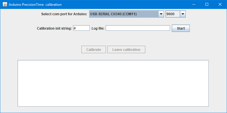
For fastest and most precise calibration the PC program requires a PC with very few programs running during the calibration. It is possible to calibrate on a busy PC, but it will take longer to get a stable calibration. It is also possible to connect multiple Arduinos and use multiple instances of this program to calibrate more at the same time.
The program is in Java and requires that Java is installed.
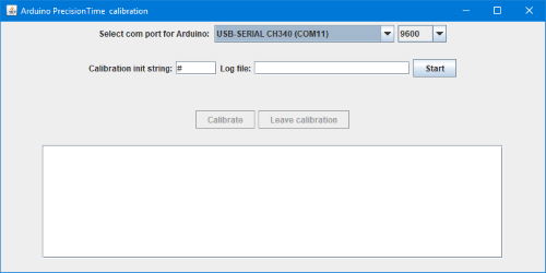
When the program is started the serial port and baud rate must be selected and the "Calibration init string" adjusted to the one actually used, for the test sketch the # is correct.
If anything is written in the "Log file" field a log file will be created with the time of the PC and Arduino during calibration.
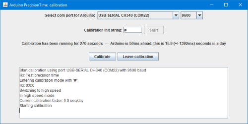
First program the Arduino from the Arduino IDE, but do not open the terminal, then press Start.
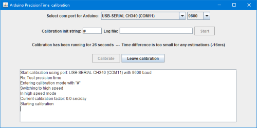
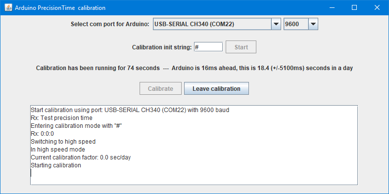
The software will switch the Arduino into the PrecisionTime calibration routine and change the baud rate. If anything fails it will abort.
The lines starting with "Rx" is random messages received from the Arduino.
Current calibration factor is the current value stored in the Arduino or 0.0 for the first run or if EEPROM location is changed.
Pressing Leave calibration will tell the Arduino to exit the calibration routine and will close the serial port on the PC (i.e. the Arduino IDE can then access it).
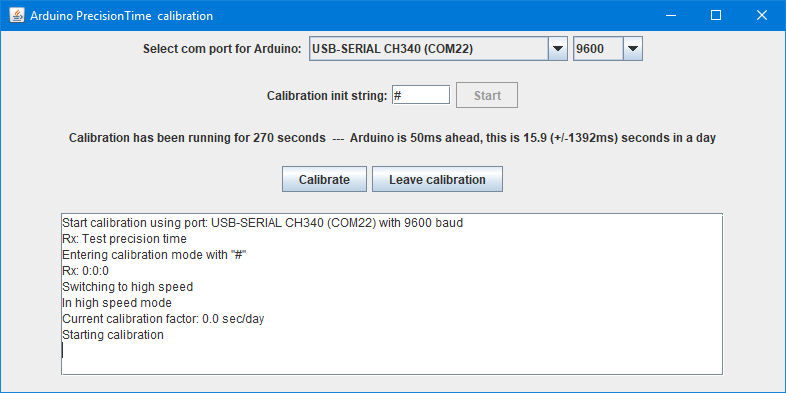
The status line will shown how long the calibration has been running and initially only the difference between the PC and the Arduino.
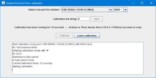
When the calibration has been running for some time and the time difference between the PC and Arduino is large enough the status line will include a estimate of the daily time error. The +/- value is how much the daily error varies during the last 20 measurements, this need to be low for a good calibration.
After some time the Calibrate button will be enabled. The time will vary from 30 seconds to a couple of minutes, depending on how stable the estimates are. With a already calibrated Arduino it may take much longer before the Calibrate button is enabled.
The calibration button will only be enabled if calibration is possible, when testing RTC's it will never be enabled.
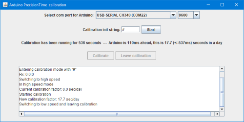
Pressing the Calibrate button will transfer the calibration factor to the Arduino, that will save it in EEPROM, then the Arduino will leave the calibration function and the PC will close the serial port.
It is possible to do multiple calibration on the same Arduino, the calibration factor will be adjusted correctly.
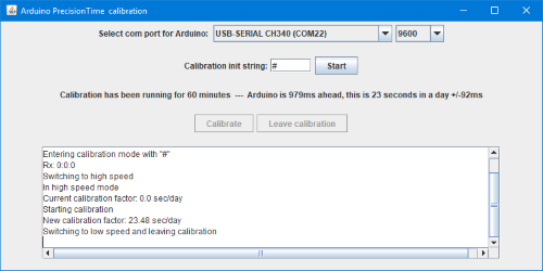
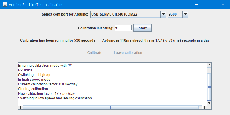
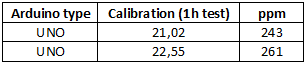
Here a Arduino is calibrated after 1 hour where it was about 1 second to fast.
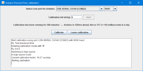
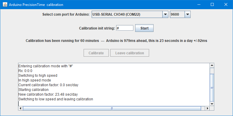
Starting over and running for more than 9 hours (580 minutes) the calibration has mostly removed the error, it is only about 0.1 second to fast in the 9 hours and a estimated 0.3 second a day.

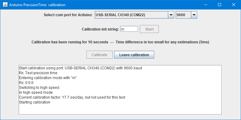
Using "m" instead of "#" with the test sketch will use the millis function for time, i.e. show the uncalibrated values and it is not possible to store a new calibration.
Testing RTC's
The PC program can also be used to test RTC's, this requires another sketch that will fetch the seconds from the RTC instead of using the millis or the library. This sketch is included.
Code:
// Select one RTC chip
//DS1302 rtc(A3,A5,A4);  // Note pin assigment: A3:CE/RST, A5:CLK, A4:DAT

// A4:SDA, A5:SCL on UNO and Nano
//DS1307 rtc;
DS3231 rtc;
//PCF8563 rtc;
//PCF8583 rtc;
Uncomment the used RTC chip and connect it to the pins listed, then upload it to the Arduino.
The PC program is used the same was as above with the "Calibration init string" being #. The calibrate button will not be enabled, it will only list the timing erros.
Supported processors
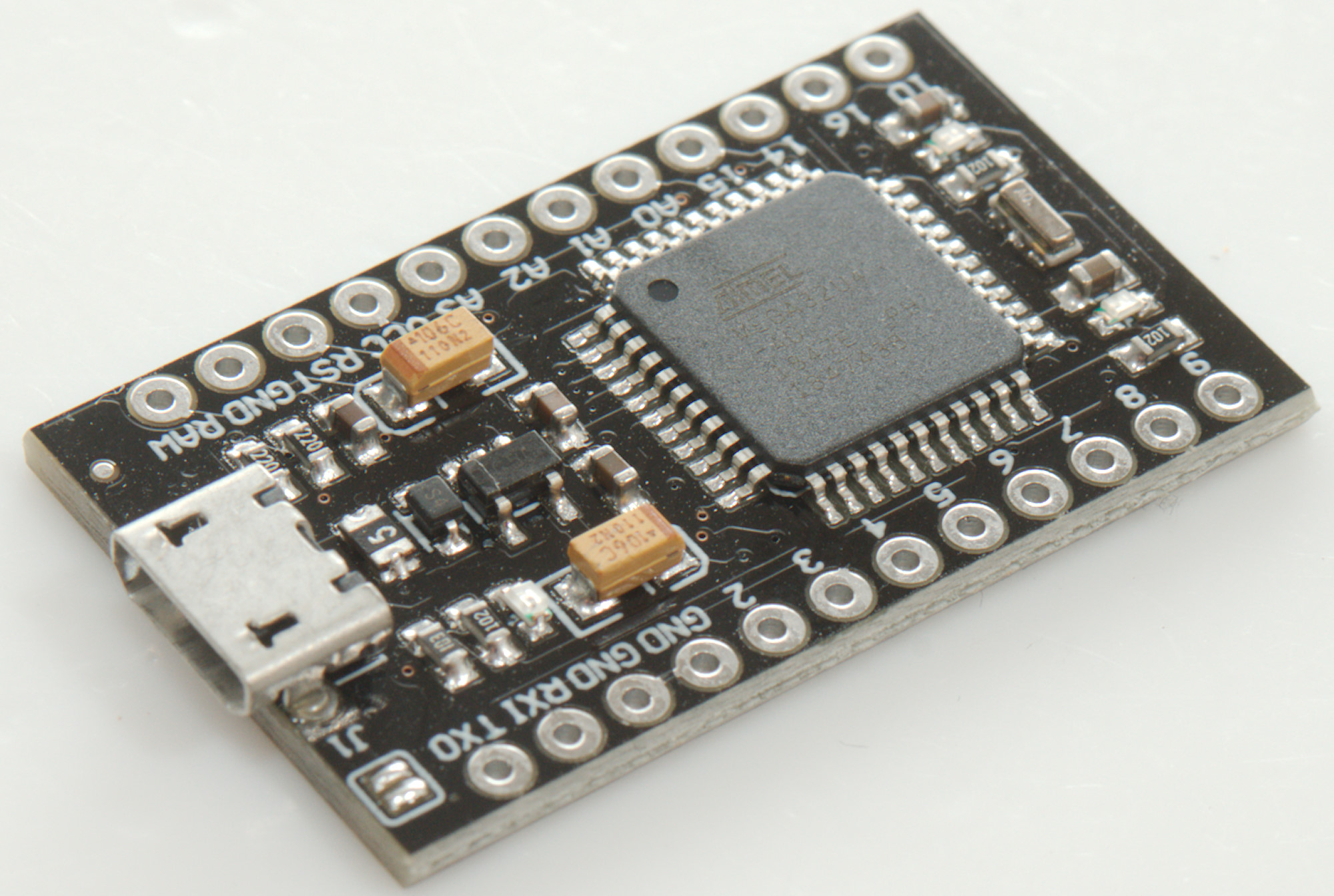
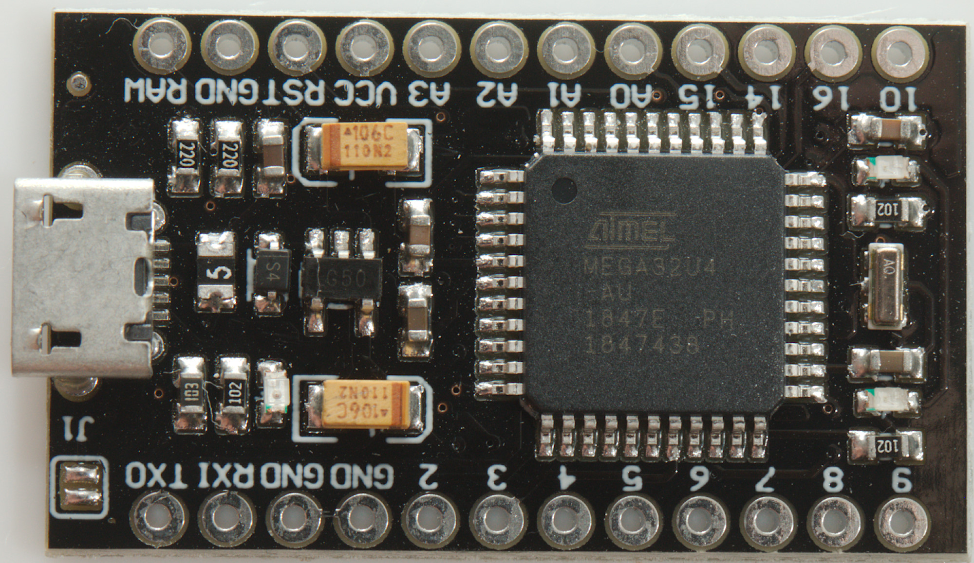
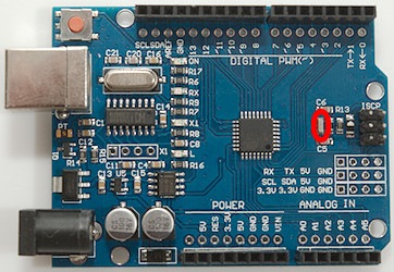
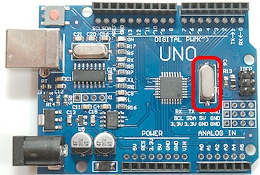
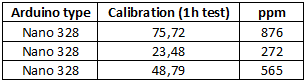
The calibration in the table is seconds a day a clock would drift, I measured over one hour to get good precision. I have marked the processor crystal/resonator on the pictures. There is a line in the tables for each unit I have tested.
All tested boards are cheap versions from Ebay or Aliexpress, except Nano Every.
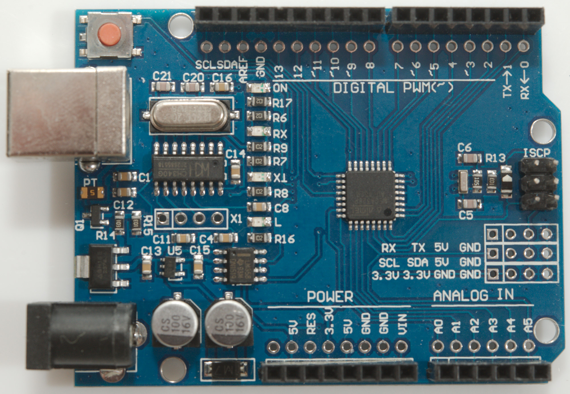
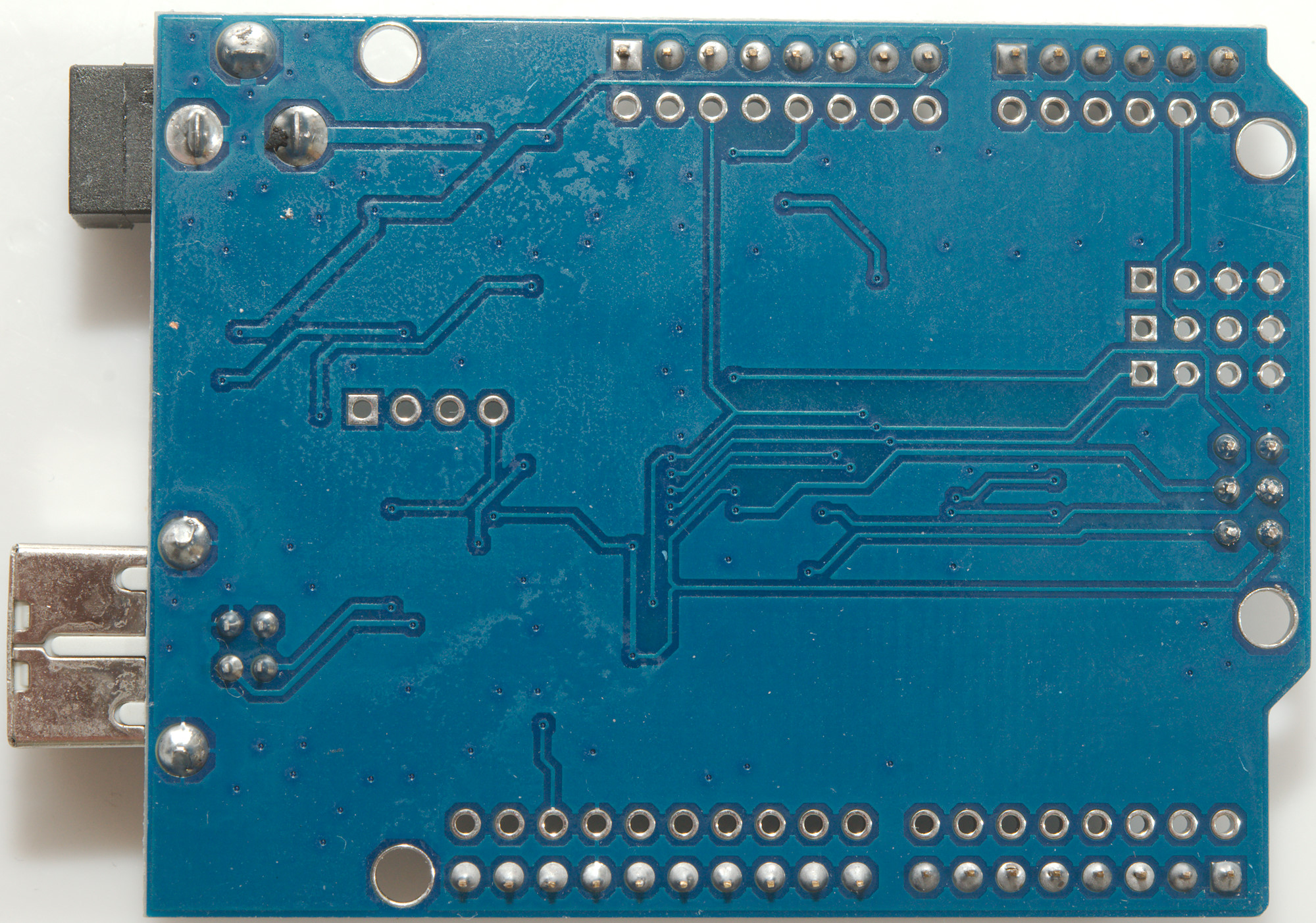
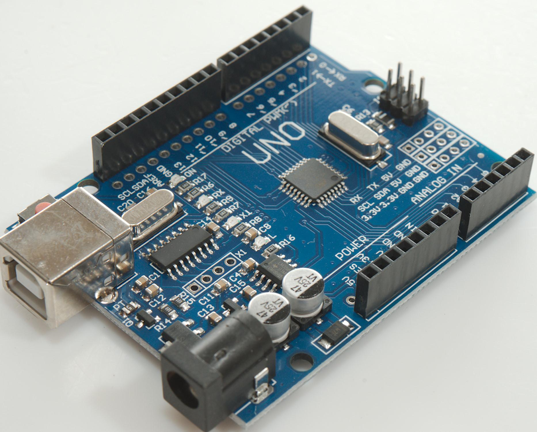
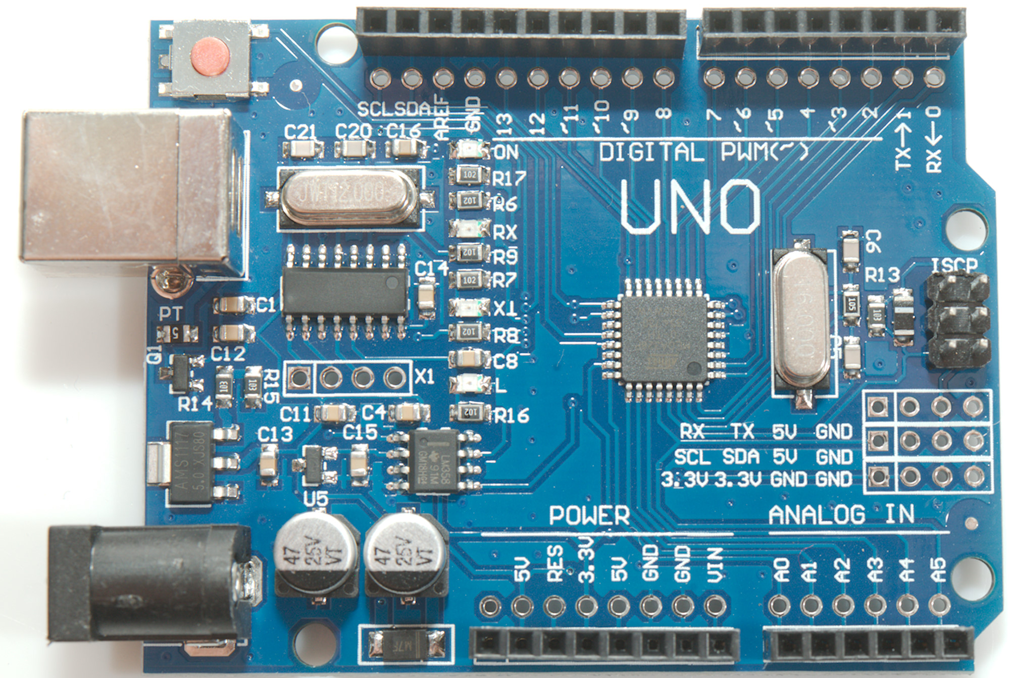
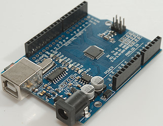
Arduino UNO (Mega328)


This processor support Timer1 & Timer2
There are two crystals on this board, a very small one for the processor (Probably a ceramic resonator) and a larger one for USB. As can be seen from the table the processor has a large deviation on the clock.
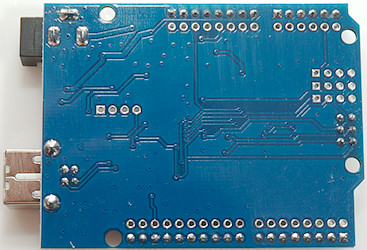
A few places sells another UNO with a crystal for the processor.
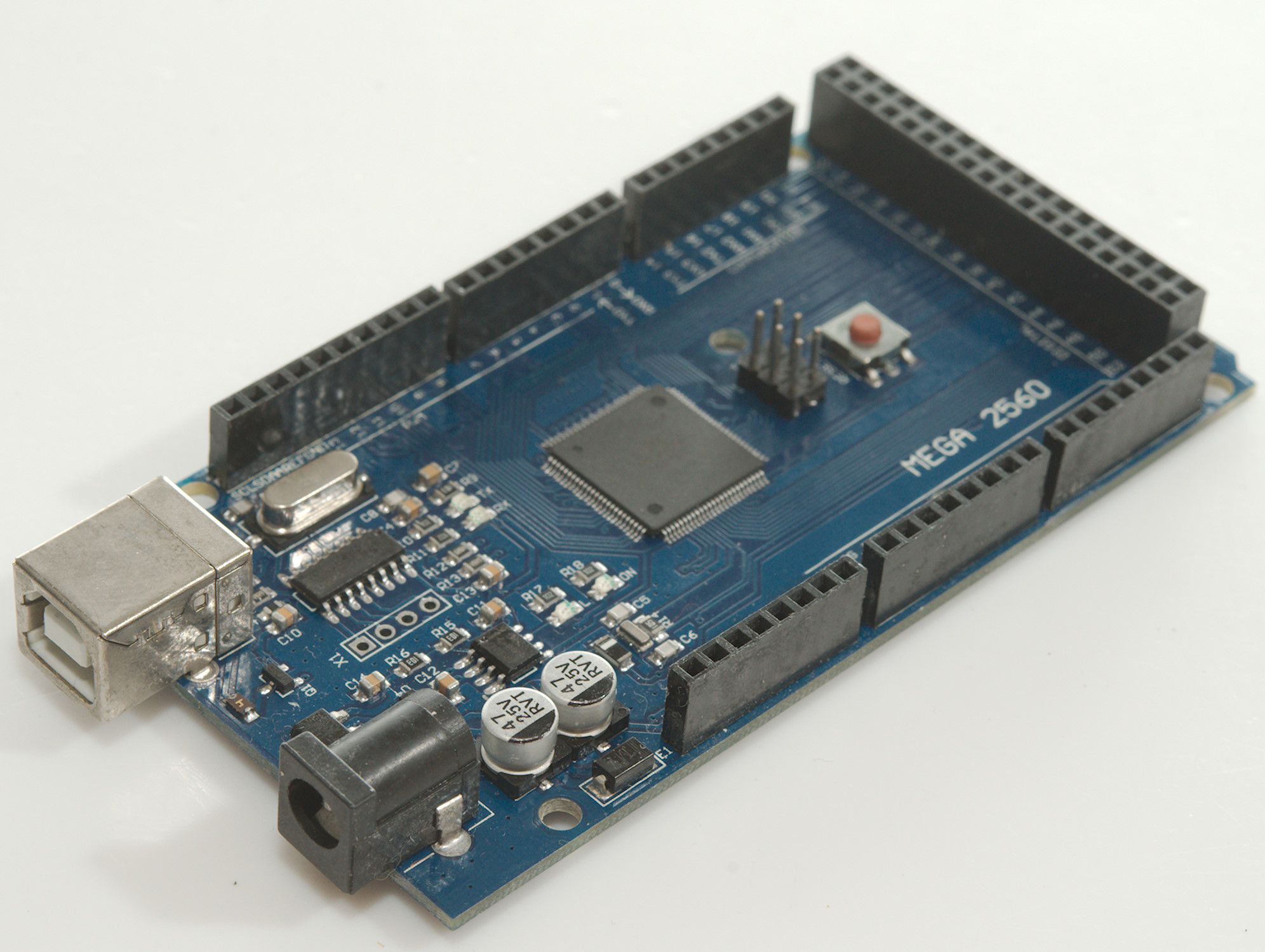
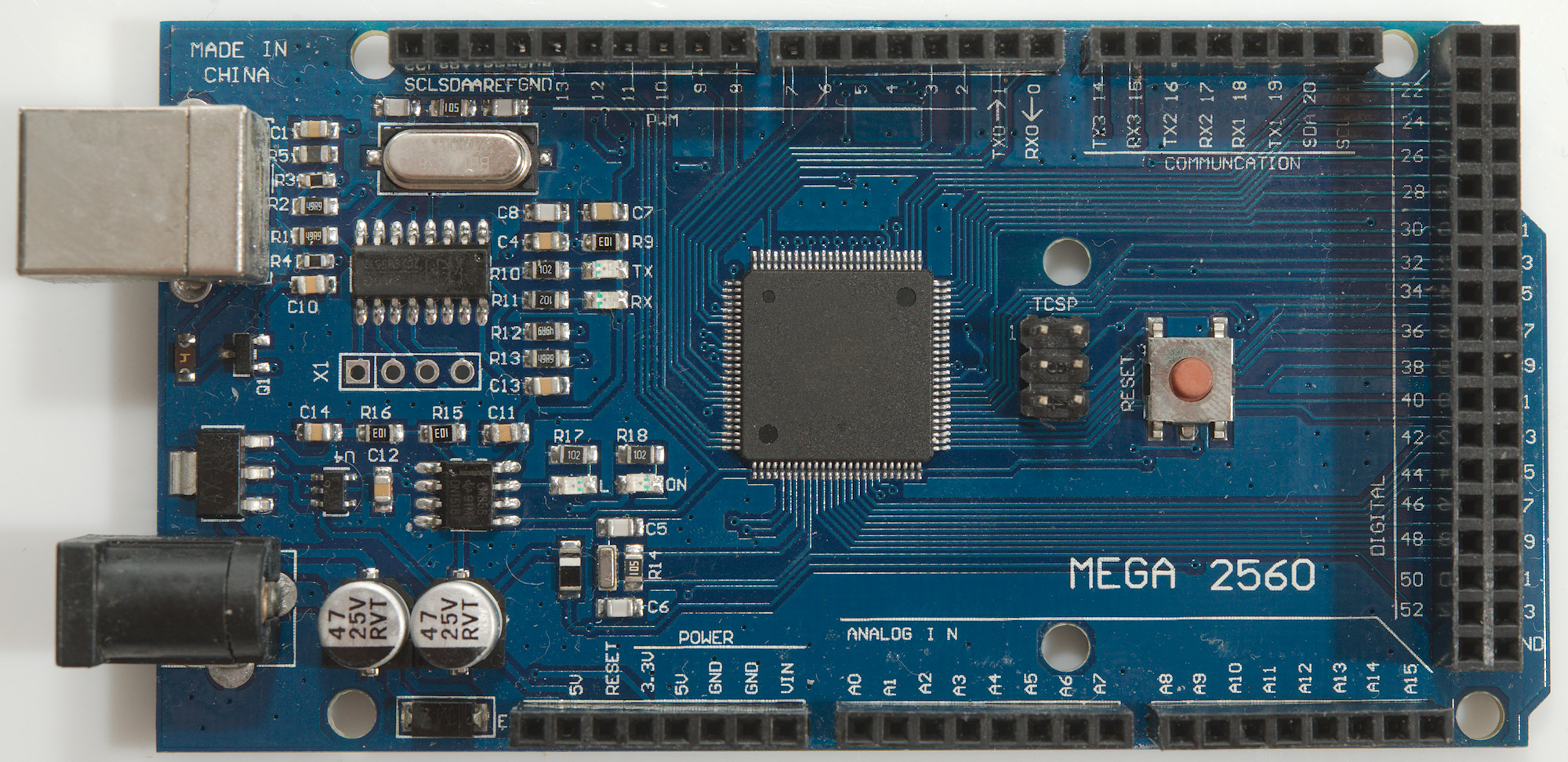
Arduino Mega (Mega2560)

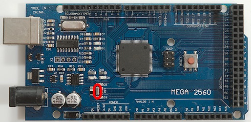
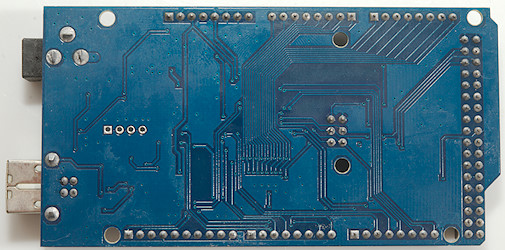
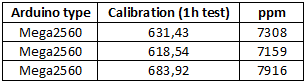
This processor support Timer1, Timer2, Timer3, Timer4 & Timer5
There are two crystals on this board, a very small one for the processor (Probably a ceramic resonator) and a larger one for USB. As can be seen from the table the processor has a large deviation on the clock.
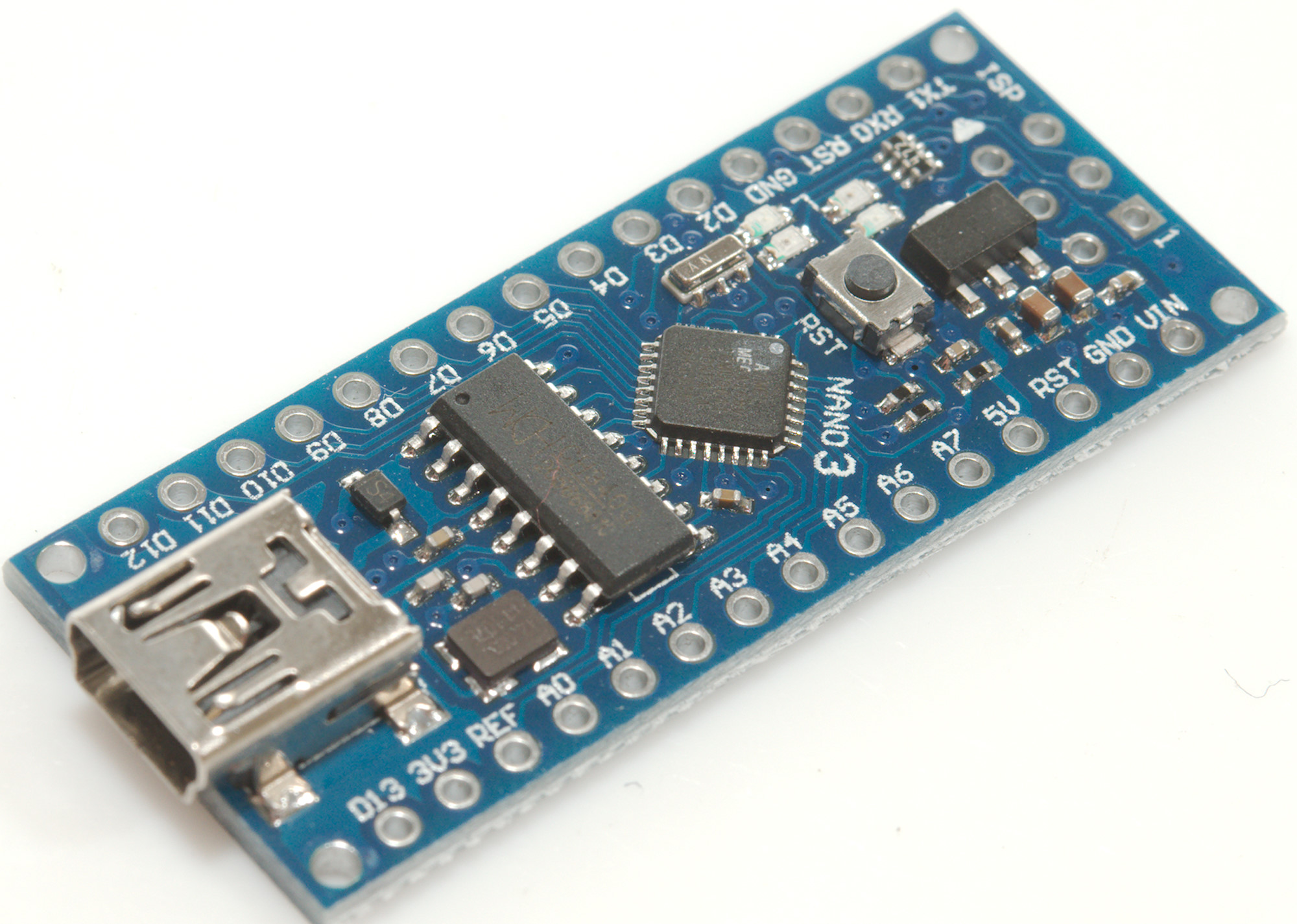
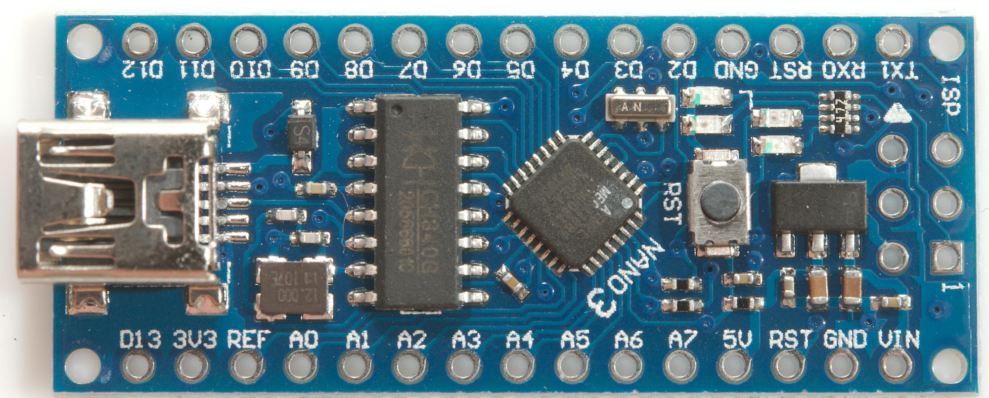
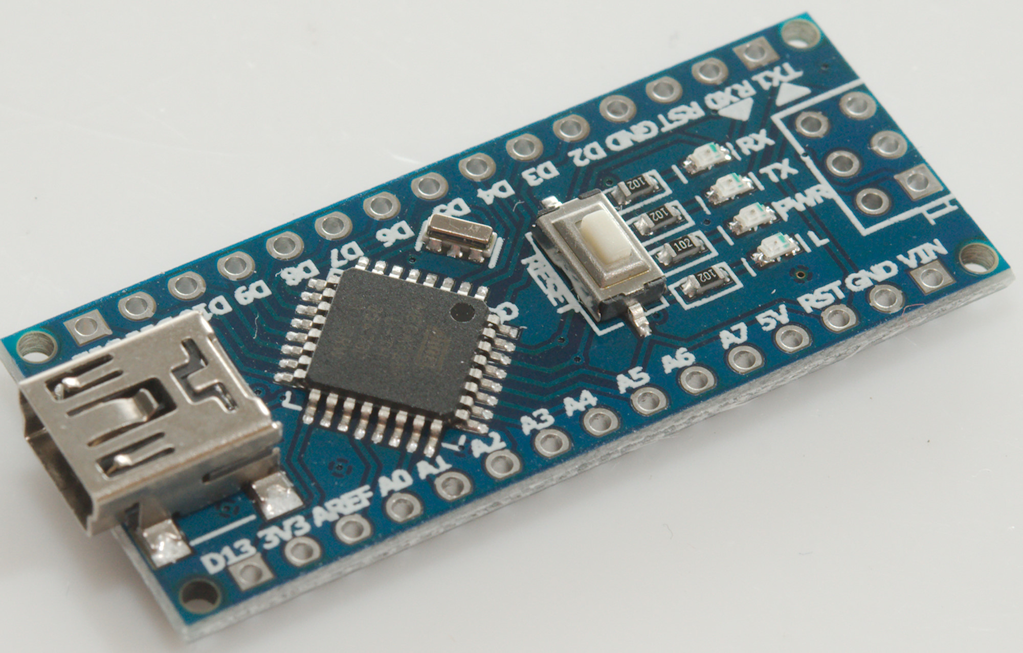
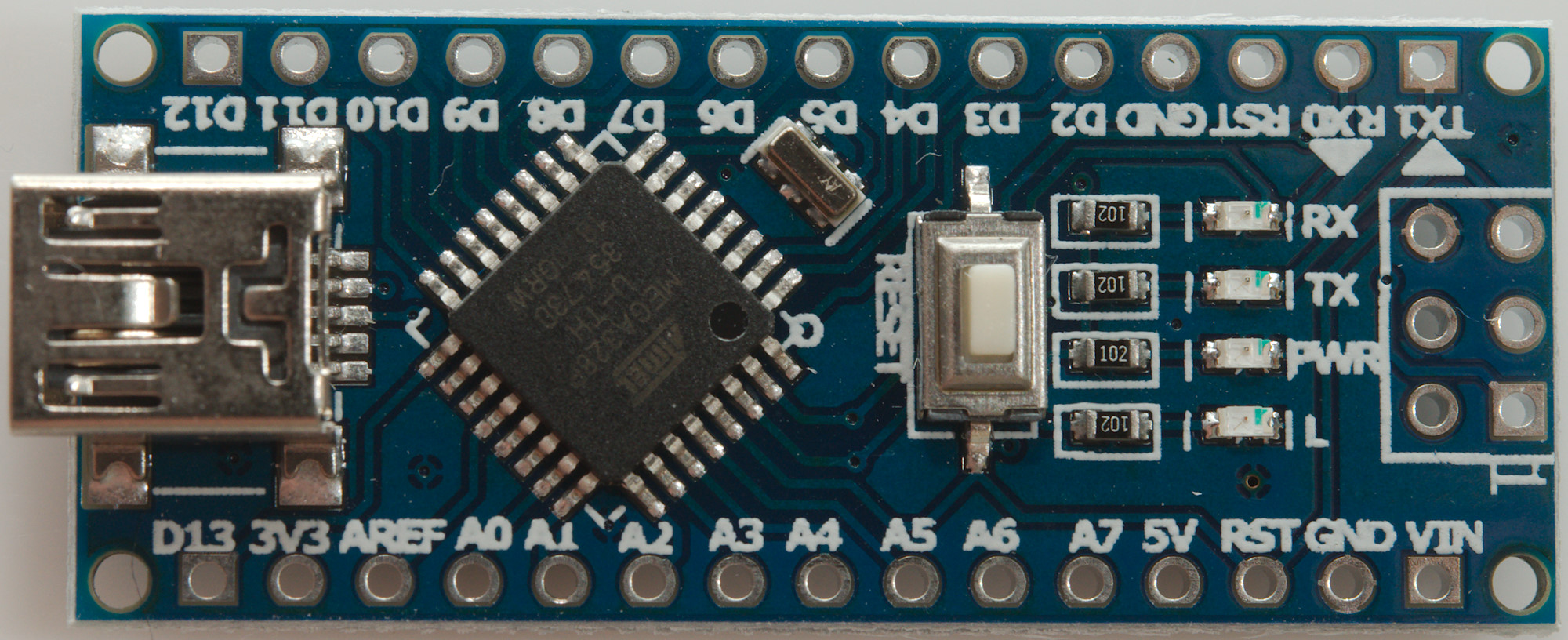
Arduino Nano (Mega168 & Mega328)
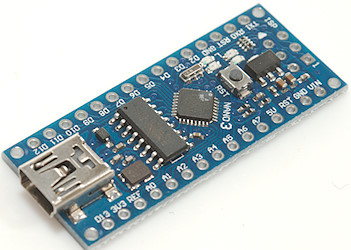
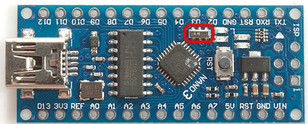

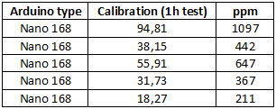
There are two crystals on this board, a very small one for the processor (Probably a ceramic resonator) and a larger one for USB. The frequency is not precise enough for clocks, but not bad either.
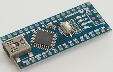
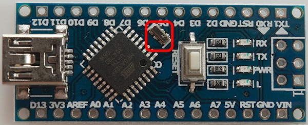
These processors support Timer1 & Timer2
On this board there is only one crystal because the USB chip has a build in oscillator (On CH340C, CH340E and CH340B), but there is space for an external one near C4 if using another chip (CH340G, CH340T and CH340R). The frequency is not precise enough for clocks, but not bad either.
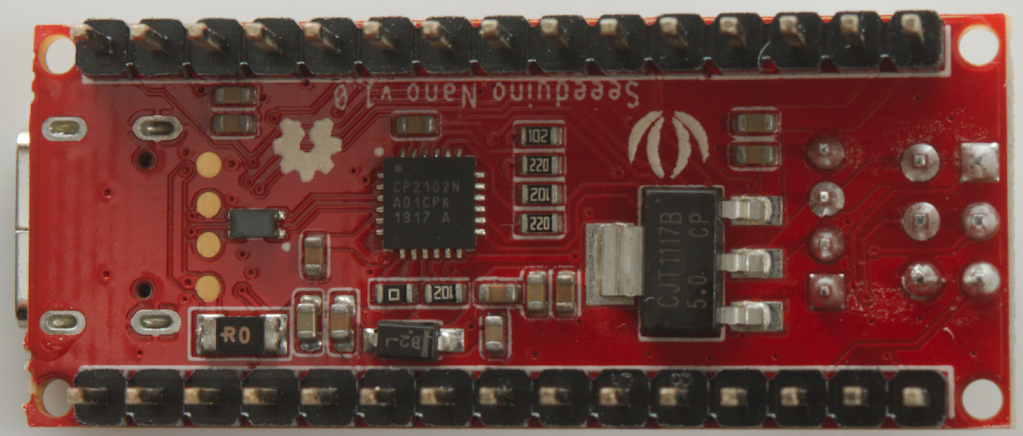
Seeeduino Nano (Mega328)
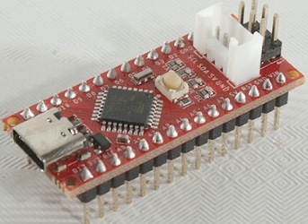
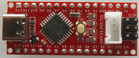
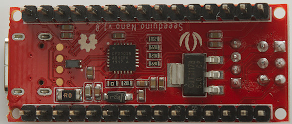
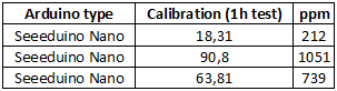
This is a Nano clone, but with some improvement: USB-C connector, Grove connector and delivered with pins soldering in. It is from Seeed studio.
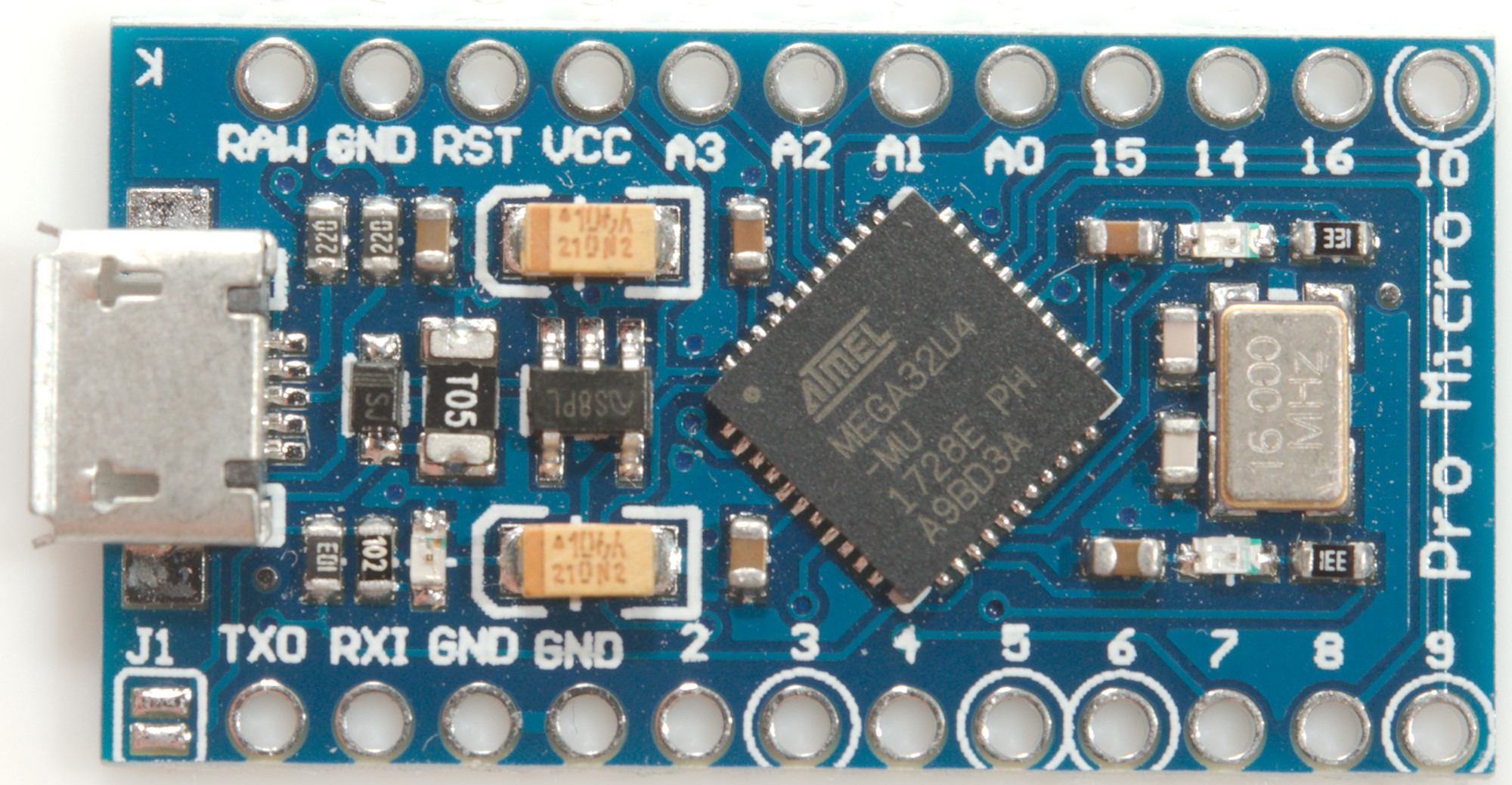
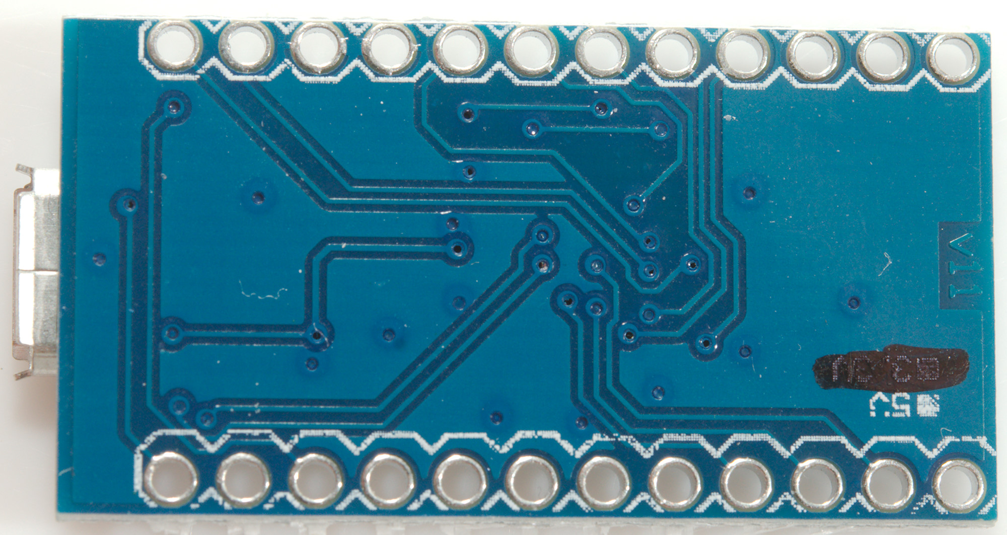
ProMicro simulating Arduino Leonardo (Mega32U4)
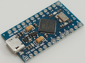
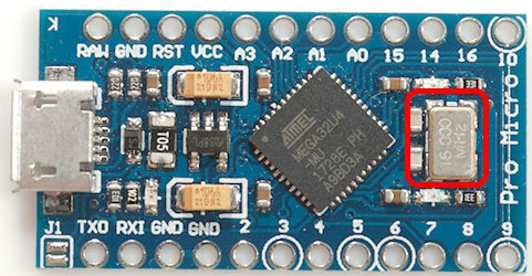
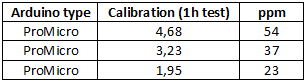
This processor support Timer1, Timer3 & Timer4
This board has one crystal, because the 32U4 processor includes the USB interface. I am rather impressed with this precision, but it is still not perfect for a clock.
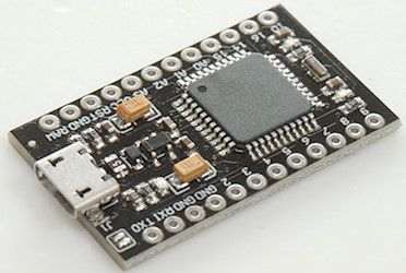
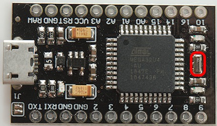
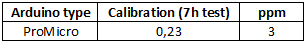
This ProMicro has something that looks like a ceramic resonator, but precision is as good as a crystal.
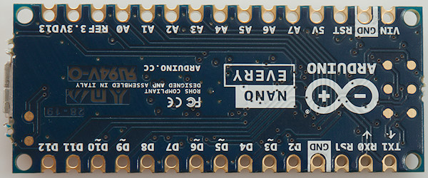
Nano Every (ATMega4809)

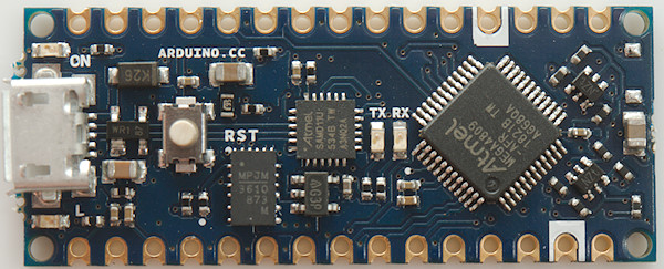
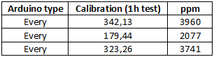
This processor do not use a crystal or resonator, but an internal oscillator in the processor. This means very bad clock precision and high sensitivity to temperature and probably also voltage. This means it is important to do any calibration at the same temperature and voltage as the processor is going to work at.
Other
I have not tested with other boards, but I would expect the full library to work on any Arduino based on a Mega processor.
For Arduinos with non-mega processors the user must setup the 1000 interrupts a second and call the updateIntr(), as long as the processor supports EEPROM the rest will work.
Tested RTC's
The precision is seconds error in a day measured with the application, i.e. the precision of the PC clock will affect the result.
All tested boards are cheap versions from Ebay or Aliexpress.
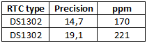
DS1302

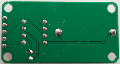
DS1307

DS3231
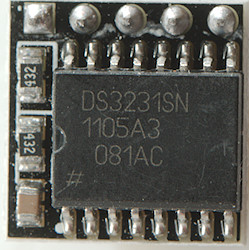

This RTC register about 0.5 second error in a day, some of this (or maybe most) is from the PC clock.
PCF8563

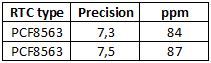
These RTC's are a few seconds too fast each day.
Conclusion
This library makes it very easy to get good time precision on a Arduino, the limits are the precision of the PC time and how stable the crystal/ceramic resonator is. In praxis I can get down to about 1 second a day precision with my PC.
It has many options on how to use it, either with a calibration build into the user program or with a separate calibration sketch. It can maintain a clock, even with standard C structures or the user can just use the precise seconds.
Most RTC's will not be better and often is slightly worse than a Arduino with a crystal that is calibrated, the exception is RTC's based on DS3231, they are very precise. A Arduino with calibrated ceramic resonator can also be fairly precise, especially if the temperature is stable.
Notes and download
The calibration factor is specific to each Arduino and has nothing to do with selected interrupt, i.e. calibration will be valid even if interrupt is changed.
Precision time library with examples
Test RTC sketch
PC program
PC program source code