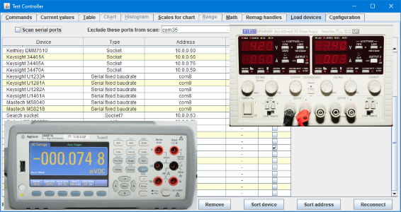
TestController, Configuration of a SCPI devices
Many SCPI devices can be configured without any real programming, "just" by writing a configuration file. All existing devices have a configuration file that can be looked in for examples.
Non SCPI devices have internal driver code and used the definitions as a supplement to this, multiple devices may share the same internal driver, but with different definition files.
Main Test controller page
Contents
Device drivers overview
Difference between the 3 SCPI/ascii drivers (SCPI, SCPIx, Ascii)
SCPI
SCPIx
Ascii
Definition overview
The device identification and connection parametes
GPIB settings
GPIB Control
Data type definitions
Basic communication
#initCmd
#finalCmd
#prepareSample
#askMode
#modeFromValue
#askValues
#outputOff
Fixing format and other issues
readFormat
mathFormat & readmath
Timing issues
Arduino startup reset
Selecting mode (Mostly for multimeters)
Selecting multiples modes
Configuration menu
Tags
Control number
Control numberInt
Control numberDual
Control text
Control button
Control buttons
Control buttonsOn
Control radio
Control checkbox
Control combobox
Control comboboxHot
Control info
Control infoAsk
Control slider
Control indicator
Control indicatornum
Control multi
Control set
Control separator
Control color
Control selector
Control updater
A generic interface
Definition of set...
Definition of get...
Definition of read...
The #interfaceType definition
Miscellaneous tags
#author
#mayModifyMode
#notes
#noteImages
#help
#helpurl
The Other popup
#otherList
#otherImage
#otherData
#otherFunc
#otherText
Examples
Creating multiple devices from one configuration file
#meta
#metadef
#idstring, #name, #handle, #port, #driver, #baudrate, #subdriver, #baudrate, #subdriver, #usbvendor, #eol, #verifydevice, #help, #checksum
#replace
#remove
#removeline
#replacetext
#sections
#metaDebug
Protocol is nearly SCPI, but there is a few issues (SCPIx)
User supplied stuff
Non SCPI device drivers
Main page
Functions for use in calculator and definitions
Device drivers overview
| Name | Type | Interface | Purpose |
| SCPI | Command | Ascii | SCPI and SCPI like devices |
| SCPIx | Command | Ascii | Nearly SCPI devices (Many Chinese SCPI imlementations) |
| Ascii | Command | Ascii | Devices with ascii commands (Many old devices) |
| SingleValue | Streaming, poll | Ascii | DMMs that sends a single line with value and unit |
| Binary DMM protocol | Streaming | Binary | DMMs that sends binary data (Like 7 segment encoding) |
| Modbus | Command | Binary | Devices with Modbus |
| AsciiBin | Command | Binary | Devices that packs ascii data in a binary frame |
| Block | Streaming, poll, command | Binary | Binary fixed length data block |
| AsciiBlock | Streaming, poll, command | Binary | Multi line ascii and ascii blocks |
TestController contains other drivers, they are generally designed for a specific device or specific series of devices. These are not included in the documentation.
Type command is drivers where TestController send a command and wait for answer each time a value must be updated.
Type streaming is drivers where the device send a message continuous with its states/values.
Type poll is where the device need a command to send a message, but it do not support anything else or is very slow to answer.
Type streaming and poll will be running in the background and not slow down update or logging in TestController, but may return the same value multiple times.
Ascii interface is a text based interface where each line from the device ends with a CR or LF character.
Binary interface send binary data and CR/LF and other control characters have no special meaning.
TestController will select interface depending on device driver. Using a interface that do not support the required Ascii/Binary format will prevent the definition from loading.
Possible interface for driver:
- Ascii: Socket, LXI, com, comFixedBaud, comNoBaud, GPIB
- Binary: Socket, com, comFixedBaud, comNoBaud
Difference between the 3 SCPI/ascii drivers (SCPI, SCPIx, Ascii)
Test controller supports 3 different main drivers for two way ascii communication with a device, in some ways they are similar, but there is also significant differences.
SCPI
This is the default driver and is used when no driver is specified.
- It will always use the *idn? command to identify a device and will not accept a device without a answer that matches the selected device.
- Anything typed on the command line will be passed directly to the device, except when starting with # or =
- Unsolicited data from a device will be shown in the log window.
SCPIx
This is a slightly modified SCPI driver
- It will always use the *idn? command to identify a device and will not accept a device without a answer that matches the selected device.
- The answer from *idn? can be modified with #modifyIDN before comparing to selected device.
- There is a option (#forceUpperCase) to force any command into uppercase before it is transmitted to the device.
- It is possible to define commands with #scpiCmd (The commands used to redefine can also be used from the command line).
- It can directly control a GPIB interface with [CLR], [LLO], [LOC], [TRG]
- Anything typed on the command line will be passed directly to the device, except when starting with #, =, matching a #scpiCmd definition or internal command.
- There is a option to remove a prompt from the device (#removePromptChars)
Ascii
This driver is for devices that do not follow SCPI command syntax (Like sending answers to commands without a ? character).
- Driver can connect without identifying the device.
- A simulated *idn? command can be implemented with #verifyDevice, getdevicesn? and getdevicesw?, this add identification/verification.
- Only commands defined with #scpiCmd is passed to the device (The commands used to redefine can also be used from the command line).
- It can directly control a GPIB interface with [CLR], [LLO], [LOC], [TRG]
- It supports slowing down communication with #cmdDelayTime
- This driver will generate a command list in the help window, based on the defined commands.
Definition overview
A device definition consist of different sections, some are mandatory before the device will work at all, other is nice to have, but not strictly required. The sections are not separated in the device configuration, but the identification section must be first for the definition always to work.
The sections are:
- Identification and handle. This section is use to establish a connection with the device and name it.
- Data type definitions. This section defines what data can be expected from the device.
- Basic communication. This section will fetch the data listed in the data type definition.
- Mode selection. This section is mostly for bench multimeters and adds a mode selection menu.
- Configuration menu. This section adds a configuration popup for the device.
- Interface. Adds a generic scripting interface for the device, this means it can be controlled without using device depend SCPI from a script.
- Miscellaneous. A few tags did not fit any of the above and are listed here.
The 3 first sections must be implemented for the device to work at all. For bench multimeters a mode selection is usually required and for power supplies, electronic loads, and many other devices a configuration menu is very nice to have.
The interface is never required, but will make scripting much more flexible.
It is possible to create multiple similar devices from one configuration file, this has its own chaper.
The device identification and connection parametes
These must be placed first in the configuration file.
The start of the file is:
Code:
#idString first two parts of *idn? answer
#name The device name
#handle A short handle
#port The port used
#baudrate Baudrate for serial devices
#driver Internal driver to use, not used for SCPI
#help Help file to use
#eol Used to change the standard LF end of line to CR or CRLF.
Two real examples:
Code:
#idString Keysight Technologies,34465A,
#name Keysight 34465A
#handle K34465
#port 5025
Code:
#idString HEWLETT-PACKARD,34401A,
#name Agilent HP34401A
#handle HP34401
#port com
#baudrate 9600
The idstring is the brand name and the device name and must exactly match the text returned from the device, the two last parameters must not be included.
The name is the name used in TestController for the device
The port can contain one or more of off:
Number: The port number for a socket connection, this is usually hidden somewhere in the documentation for the device.
LXI: LXI connection.
com: Serial port with baudrate setting on the "Load Devices" page.
comFixedBaud: Serial port with fixed baudrate
comNoBaud: A virtual serial port that do not use baudrate.
GPIB: A IEEE488/GPIB port, this requires the use of a adapter, the adapter type is not related to the device configuration.
When multiple ports are listed it is possible to select between them with a combobox on the "Load devices" page.
For a modern device with multiple connections ports it could be something like:
Code:
#port number LXI com GPIB
Both number and LXI uses a network connection, com can be a physical RS232 port or a virtual USB com port, GPIB requires the use of a supported IEEE488/GPIB adapter.
The baudrate can be any baudrate, but can also contain more parameters line: 19200O71Dr
The D or d sets DTR high or low and R or r sets RTS high or low.
The last letter can be H for DTR flow control (Windows only) or h or RTS flow control.
For eol a string is used, to write control character escapes must be used, use: /r for CR and /r/n for CRLF
GPIB settings
The GPIB port has some settings that can be adjusted, these settings will track the device, i.e. multiple devices on the same GPIB adapter may use different settings:
Code:
#gpibReadEol eoi
#gpibReadEol characterNumber
#gpibWriteDelay timeInMs
#gpibWriteReadDelay timeInMs
The #gpibReadEol defines how the device terminiates its answers, the default uses eoi. Specifying "#gpibReadEol 10" would expect a LF character for terminating a answer.
#gpibWriteDelay will add a small delay after each GPIB write, this can slow down the processing for old slow devices.
#gpibWriteReadDelay minimum time before trying to read a answer from a device. If the GPIB adapter is connected to multiple devices, this time may be used for communicating with other devices.
GPIB Control
Some meters uses the control lines of the GPIB interface for specific functions, this can be controlled with special tags in the messages send to the interface. These messages will be ignored when other interfaces are used, this means generally they are only recommended to use on devices that only has a GPIB interface.
- [CLR] Do a "Selected Device Clear" function.
- [LLO] Set device in remote control mode, i.e. the user interface on the device is disabled.
- [LOC] Set device in local control mode, i.e. the user interface on the device is active.
- [TRG] Send a trig request to the device, this will not trig all connected GPIB devices.
Data type definitions
This defines what data the device returns that must be shown on "Current values" and logged.
It will be one or more lines, each defining one data type, not all needs to be used at the same time or even used at all (The last part is when making definitions that cover multiple devices).
Code:
#value name unit format {selector}
A typical definition for a power supply:
Code:
#value Voltage V D3
#value Current A D3
#value VoltageSet V D3
#value CurrentSet A D3
A typical definition for a bench multimeter, only one is used at a time.
Code:
#value VoltageDC V d6 VDC,d
#value CurrentDC A si ADC
#value VoltageAC V d6 VAC
#value CurrentAC A si AAC
#value Resistance ohm si ohm,ohm4
#value Frequency Hz si hz
#value Ratio - d3 Ratio
#value Period s d6 Period
The name will be used for labeling the value and also for creating variables. It must be one word that starts with a letter and only contains letters, numbers or _.
The unit is shown at various places to help identify what the value is, for measurements without a unit use -.
The format uses a predefined numeric formats to show the value, the format used in a CSV file is not the same format as used on the screen, but will be with higher precision.
D0..D15 is floating point with 0 to 9 decimals.
X1..X15 is floating point with up to 1..9 decimals (A X0 is accepted and converted to a D0)
INT is integer format and is similar to D0, except when saving where it will save without any decimals.
SI will use SI prefix, i.e. Mkmu etc. after the number and will show from 0 to 7 decimals.
SI3..SI15 will use SI prefix and limit the number of digits (not decimals) to 3..9.
SI3..SI15x where x is on of _munpfazy will limit the minimum SI prefix to the specified prefix
DIGITAL(B0,B1,B2,...) This switches the value to digital mode, this means all values are converted to integer and handled as digital bits. The parameters are
names for each bit, use - to skip a bit. It is recommended to use short names (2 or 3 characters) for the bits.
TIME Use h:m:s format, value is in seconds.
The selector is used together with #askMode and #cmdMode, it is a list of device modes that must either match the mode name from #cmdMode or the result returned from #askMode. Multiple modes can be listed for each column, use a comma as delimiter.
Basic communication
This is the SCPI commands used to read and control the device. The SCPI commands can be listed after the tag with ; between them and/or on the following lines, until the next # tag.
Any command with a ? will be assumed to return an answer. A single line may contain multiple commands that each returns answer.
If a delay is needed between the SCPI commands use [delay].
Code:
#initCmd SCPI commands
#finalCmd SCPI commands
#prepareSample SCPI commands
#askMode SCPI commands
#askValues SCPI commands
#outputOff SCPI commands
Some examples, the different lines are not from the same device:
Code:
#askValues V1O?;I1O?;V1?;I1?
#askValues read?
#askValues :read? "defbuffer1",read
#initCmd :SYSTEM:REMOTE;[500]
#finalCmd abort;*cls;*rst;init;system:local
#prepareSample abort;sample:count 1;trig:source imm;trig:count inf;init
#initCmd
This command is used once after the device is connected, it is typically used to switch the user interface to remote control. This is not always required.
#finalCmd
This command is used once just before the connection is closed, it is typically used to switch the user interface to local control, turn power supplies off and set voltage and current to low values, turn electronic loads off and turn generators off. This is not always required.
#prepareSample
This is used before reading from the device and after each mode change, this is used to setup trigger mode. This is not always required.
#askMode
Returns the current mode, this is used to select the data types to expect when reading from the device. It must match either either directly with the select from #value or with the mode from #cmdMode
The value from the meter may not always work directly, see next chapter for ways to modify the results.
The return string may contain multiple modes, this may be necessary for #cmdModeCheck
It is possible to add a button for a #askMode by using "#cmdModeGet" definition.
#modeFromValue
For devices that may change mode outside of TestController commands and where the actual mode can be decoded from #askValues, this definition can be used.
It need a expression to convert the answer from #askValues to a mode
It is strongly recommended to use same parameters to #askMode & #askValues, also #askModeMathFormat & #modeFromValue must use the same parameters.
Code:
;Answer from device is: mode,value
#askValues value?
#askValuesReadFormat xs

#askMode value?
#askModeMathFormat getElement(value,0)
#modeFromValue getElement(value,0)
#askValues
This is the SCPI string to return all data for "Current values" and logging, it can contain more command with ? in them, but it will limit the fastest logging rate. All values must be numeric values.
The input string is split into segments on all spaces, commas and semicolons and each segment is assumed to be a value.
The values from the meter may not always work directly, see next chapter for ways to modify the results.
#outputOff
Turn power supplies, electronic loads and generator output off. This definition is used when the "Outputs off" button is pressed.
Fixing format and other issues
When asking for values not all devices return just the value, some will add something before or after the value, this will prevent the #askValues & #askModes from working directly, the result must be adjusted a bit.
Code:
#askValuesReadFormat a list of what value to use and what value to remove
#askValuesMathFormat  expression, input is called value
#askModeMathFormat  expression, input is called value
#readingDelay time in seconds
#modeChangeDelay time in seconds
readFormat
This is a simple way to edit the returned values while converting the data to numbers. It consist of a list of characters, each with a specific meaning:
- x: Skip this value
- u or U: Remove any letters after the number, before trying to convert it.
- f or F: Regular number
- s or S: Number with optional SI prefix (pnumkMG).
- *: Control value, when this is 0 all values parsed with U, F or S will be zero. This is typically used with device that return last on value when output is off.
The input is processes by readmath and split on , and space before using this function.
mathFormat & readmath
This makes it possible to run a script on the returned string, before any other processing is done. The original input string is called value.
A simple script may be to remove quotes around the value:
Code:
#askModeMathFormat unQuote(value);
See a list of useful functions here .
When using any type of readmath it may be a good idea to enable debugging. Use the command "#debug handle" where handle is the handle for the device you are working on. This will list a couple of items. Each item can be enabled with "#debug handle item".
Timing issues
There are a couple of ways to handle timing issues, each has advantages and disadvantages.
Use a [*OPC] tag (Not all devices support this) after the SCPI command will delay until that command is done, this can be a good solution when doing different types of mode changes, but may block the communication if used after a trigger command. The [*OPC] tag will not wait more than 10 second. This function uses the *OPC SCPI command followed by some *ESR? commands, when logging only the actual delay will be shown.
Use a [delay] tag after a SCPI command, the maximum delay is [9999]. This will give the device a fixed time to process the command, before more communication is attempted. This is a last resort solution, it is better to use [*OPC].
Example:
Code:
:OUTP:STAT ON;[*OPC]
:OUTP:STAT ON;[500]
Another way to handle a slow device is to increase the timeout. The default timeout is 1 second, this may not always be enough, there are two settings for this:
#readingDelay is used to allow more time for reading values from the device
#modeChangeDelay give the device time to change mode, a value of 10 (seconds) will usual be fine.
Arduino startup reset
TC has a build in 2 second delay when initializing serial ports, it is enough for the Arduinos I have worked with, but not for all types of Arduino.
There are two ways to extend this delay:
Code:
#resetDelay seconds

#resetDelay 3.5
Add the #resetDelay in the device definition, this will work when the device is loaded, but will not find it during a "Scan serial port" operation. It is recommended to use this for all Arduinos that requires more than 2 seconds to reset.
For also handling the "Scan serial port" a command line option can be used on TC, this option is resetDelay=seconds
Selecting mode (Mostly for multimeters)
Some devices can run in different modes, that may mean they will return different values. To control this a mode change menu need to be defined. These commands cannot be used while logging, because they need to change what columns of data the device returns.
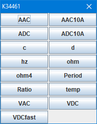
It may look like the above.
Code:
#cmdMode modeLabel deviceModeString SCPI commands
Each mode (button) needs a definition consisting of:
- The label used on the button (This is the same value used for the #value selector).
- The string the device return with #askMode command
- Some SCPI commands to select this mode. This can be on the same line or the next couple of lines.
A example for one mode:
Code:
#cmdMode ADC CURR:DC
*cls;
:SENSE:FUNCTION:ON "CURR:DC"
sense:curr:dc:nplc 1
All defined modes are shown in a popup window, where they are sorted in alphabetically order. It is possible to take over definition of this window by defining the window size:
Code:
#cmdModeLayout columns row
A button to request a #askMode can be defined with:
Code:
#cmdModeGet Button_Text
It is also possible to add empty positions with:
Selecting multiples modes
For some devices it can be useful with some secondary modes, that can be secondary channel enabled mode or just a mode where more values are read from the device. These modes are handled with a checkbox in the mode popup.
Code:
#cmdModeCheck modeLabel deviceModeString defaultState
mode on commands
mode off commands
modes where this mode is valid, use ! to invert mode. (This line is optional)
If the mode on/off commands contain [localmode] the state of the mode is handled by TestController and need not be included in the #askMode. With local mode it may not be necessary to send commands to the device, but only to add more columns and modify the #askValues command with the [mode:xxx] tag.
Changing number of columns ad requested data, depending on device mode:
Code:
#value Value1 V D3
#value Value2 V D3 Mode2

#cmdMode Mode1 m2 SCPI commands
#cmdMode Mode2 m2 SCPI commands

#askValues v1?;[mode:Mode2]v2?;
Changing number of columns, device mode is not used (Note: m2 test is not used, but must be present).
Code:
#value Value1 V D3
#value Value2 V D3 Mode2

#cmdModeCheck Mode2 m2 0
[localMode]
[localMode]


#askValues v1?;[mode:Mode2]v2?;
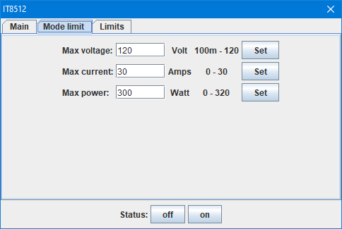
Configuration menu
This is a popup form that allows setting parameters on the device. This part of the definition file can be the most complicated, depending on how much is included in the setup form.
Parameters cannot include spaces, but a underscore will be replace with a space when displaying a text.
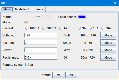
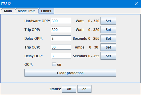
Above is a fairly complicated setup, but it do not support all functions on the device, only the most common.
Code:
#cmdSetup controlType name {page}
tags and parameters on the following lines
The definition looks simple enough. I will explain all the types and tags below, the name is the name shown to the left, it is possible to give multiple controls the same name. With no page defined the controls will be shown without any pages, but if a page is defined the menu will have a page for each name and controls without a page will be shown below the pages.
Generally each #cmdSetup will use one line on the form, but a few will combine on the same line if they have the same name. The form will use a grid with as many lines and columns as needed. Most elements in a control needs one column in the grid, but some elements may expand to more columns on grids with many columns.
A few controls do not directly add lines, but have other functions, they are: color, selector and updater
Most of the controls will synchronize with the device when the form is opened and when used, with a update tag it is also possible to make them synchronize when other controls are used. All controls with the same name will synchronize together.
Tags
Each item will have one or more tags with or without parameters.
- :read: SCPI command to read a value from the device, this is used to show the current value or status on this control.
- :readmath: Similar to #askValuesMathFormat and used to process the value from :read:
- :string: Return the read value as a string, most controls expect a number as default.
- :readformat: Similar to #askValuesReadFormat and used to process the value from :read:
- :write: Write a value to device when control is activated. What is written is a combination of this command and some parameters specified elsewhere in the control. The parameter may be added to the end or a # will be replaced with it.
- :tip: Show this tip when the mouse pointer is above the control
- :update: A list of other controls to update when this control do a write (Controls with same name will automatic be updated).
- :updatedelayed: A update is required, but not immediately. Specify delay in second after this tag, preferable not more than 0.3. This is used for devices that are slow to change their settings.
- :updatealloff: This control must be updated when "Output off" is pressed.
- :updatemodechange: Update this control when mode is changed.
- :color: Color for an indicator, can be a name or (r,g,b) values. It Is is used on buttonson indicator, "Set" buttons and separator.
- :bgcolor: Color for the background, can be a name or (r,g,b) values. This can be used with the color control
- :enable: Enable the control when this expression is true.*
- :visible: Make the control visible when this expression is true, because the form cannot resize itself, be very careful about using it (The selector control is a better way).*
- :buttontext: Text for a "Set" button
- :emptyfield: Defines a default value when input field is empty, used for Number & NumberInt
- :emptywrite: Can be used with :emptyfield: to define a special SCPI command to setup the empty condition.
- :layout: Request relayout/resizing of the form, this is needed if the contents can change size during an update. This tag is only support by control info, infoAsk and is implicit in control selector.
- :format: Specify display format (Input format is not changed), use D0..D15, X1..X15, etc. (See #value specifications), with dual and multi controls it is possible to list multiple formats.
- :textwidth: Text width of input fields (This only affect the actual typing area of an input field), default value is 6. It is possible to list widths for each field in dual and multi controls.
- :labelformat: This tag is used to format the text on the form (i.e. not buttons, edit fields, combobox or radio). It supports multiple types of format: Style: plain/bold/italic Size: one or more +, color: name or (r,g,b)
- :popupPhrase: makes it possible to add predefined symbols/word for use in text field. It must be defined as an array: array("Word1","Word2","\u1223"); and will be accessible with as a right click menu that will enter the selected symbols/word.
*Some controls will create variables with their name or pageName.name if pages are used, they are:
Number, NumberInt, NumberDual (Adds 1 & 2 to the names), buttonsOn, radio, combobox, comboboxhot, Indicator, IndicatorInt, info
To check variable names, it is possible to use (It will fail, but not before showing a list of all variable names):
Code:
:enable: displayVar(split(getVarList(1),"\n"));"
Example of regular enable/visible usage:
Code:
:enable: Config==0
:enable: !Output_2.Output
:visible: inList(Output_1.Waveform,"SQUARE PULSE");
Control number

A single number, it uses a :read: to show the current setting in the box and a :write: to change the setting when the button is pressed. The button will be labeled "Set" but this can be changed with the :buttontext: tag.
After the tags there must be one configuration line with "unit min max"
It is possible to have one value outside the min-max range by using the :emptyvalue: tag. If a special SCPI command is needed to set this up use :emptywrite: with the command.
Code:
#cmdSetup number downTime
:read: downTime?
:write: downTime
:update: Frequency,Period
:tip: Time output is low in each period
sec 0 3600
Control numberInt
The same as number, but will not accept decimal numbers.
Control numberDual

This control uses two input boxes on the same line, it uses the same tags as number.
After the tags there must be two lines each with four parameters: "unit min max name"
Code:
#cmdSetup numberDual Limits_1
:read: limits? 1
:write: limits 1
:tip: Limits, when output is outside an error is raised (Display shows RANGE)
°C -2048 2047.94 Low
°C -2048 2047.94 High
Control text

This control will use one input box that is as wide as possible. The only check and parameter that can be specified is a maximum length of the text. This can be used to send any text to a device. If only a few well defined text are accepted use a combobox instead.
Code:
#cmdSetup text up_Exp
:read: upExp?
:write: upExp
:tip: Formula for up part of wave
1000
Control button

A single wide button, there will be no name to the left, the button will use the full width.
Code:
#cmdSetup button Clear_protection Limits
:write: clearProtection
:tip: Clear current active protection (Display shows OCP or OPP)
Control buttons

One or more buttons on a line, these buttons will always have the name to the left. The command need a :write: tag and a line with two parameters for each button: "ButtonText SCPIParam"
Code:
#cmdSetup buttons RemoteSense
:write: SENSE1
:tip: Use sense wires to get exact voltage at target
Off 0
On 1
Control buttonsOn

One or more buttons on a line with a indicator last on the line. A :read: tag is needed to get the status for the indicator, it will be on if the read value matches second parameter line. The rest is similar to buttons.
The read result is supposed to be a numeric result, use a :string: tag for a non-numeric result.
Code:
#cmdSetup buttonsOn Output
:read: OP1?
:write: TRIPRST;*cls;OP1
:tip: Turn output on or off
:updatealloff:
Off 0
On 1
Control radio

A list of radio buttons that will send the setting when selected. A :read: tag is needed to select the current setting, if the returned value do not match any setting, none will be selected (It is valid to do this). The :write: tag will send the the command when a radio button is selected. For each radio button a line with two parameters are needed: "Text SCPIParam"
The read result is supposed to be a numeric result, use a :string: tag for a non-numeric result.
This creates a variable that use the name of the control (Like: Voltage for the example below) and will be the index of the checked radio button (0..) for numeric types and the actual value string for string types.
Code:
#cmdSetup radio Voltage
:read: V1?;
:readFormat: xf
:write: V1 #; OP1 1
:tip: Setup this voltage, turn output on
3.3V 3.3
5V 5.0
12V 12.0
24V 24.0
60V 60.0
Control checkbox

A single checkbox that will set/reset a setting when checked/unchecked. Multiple checkboxes with the same name will be grouped on a single line.
Both the :read: and :write: tag is needed for this control. A single line with 3 parameters is needed: "Text uncheckedValue checkedValue".
The read result is supposed to be a numeric result, use a :string: tag for a non-numeric result.
This creates a variable that use the name of the control and the label (Like: Remote_sense.on for the example below) and will be either 0 or 1
Code:
#cmdSetup checkbox Remote_sense Main
:read: sense?
:write: sense
:update: Status
on 0 1
Control combobox

A combobox that can be used to select between different non-numeric items. It needs both :read: and :write: tags and a line for each item in the checkbox with two parameters: "Text SCPIparam".
This creates a variable that use the name of the control (Like: Voltage for the example below) and will be the actual value string.
Code:
#cmdSetup combobox Waveform Output_1
:write: c1:BSWV WVTP,#
:read: c1:BSWV?
:readmath: getElement(value,1,",")
:update: Frequency Periode Amplitude Offset Duty_cycle Symmetry Arbitrary
:updatedelayed: 0.1
Sine SINE
Square SQUARE
Ramp RAMP
Pulse PULSE
Noise NOISE
Arbitrary ARB
DC DC
Control comboboxHot

This is similar to a combobox but will change the setting immediately when used and not wait for a press on a "Set" button. The configuration is the same.
This creates a variable that use the name of the control (Like: Voltage for the example below) and will be the actual value string.
Code:
#cmdSetup comboboxhot Sensor_1
:write: sensor 1
:read: sensor? 1
Type_B B
Type_E E
Type_J J
Type_K K
Type_N N
Type_R R
Type_S S
Type_T T
Voltage_1_(x8) x8
Voltage_2_(x32) x32
Control info
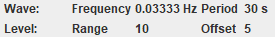
This is used to display information, multiple items with the same name will be combined on one line.
It needs a :read: tag and two lines each with one parameter, first line is unit, second line is text. To be updated other controls may need to list this control in their update tag.
This control will create vars for use in :visible: and :enable: tests, there name is control name combined with the text field.
The :layout: tag can be needed for this control.
Code:
#cmdSetup info Wave
:read: freq?
Hz
Frequency
Control infoAsk

This is used to display information, but only on request, this is typically used to fetch and show SCPI error messages. This control not show anything or update before the Get button is pressed.
It needs a :read: tag and can optionally have a line with a unit (Do not add the unit line for error messages).
The :layout: tag can be needed for this control.
Code:
#cmdSetup infoAsk Last_errors
:read: SYSTem:ERRor?
Unit
Control slider

A slider that can be used for coarse adjustment of integer values. If much more than 10 steps or precise knowledge of the value is needed a numberInt control is probably better.
It need :read: and :write: tags and a single line with 3 parameters: "Text min max"
Code:
#cmdSetup slider Display_brightness
:read: BRIGHTNESS?
:write: BRIGHTNESS
:tip: 0=off, 1=Minimal brightness, 16=Maximal brightness
_ 0 16
Control indicator


A indicator lamp, can be used to show the status of some functions (Typically output on/off). More indicators with same name will be grouped on one line.
It needs a :read: and one or more lines with 3 parameters each: "Text expression color".
The first line will be select when no match is found and the color will be in a off (low intensity) state. When a match is found the color will be shown at full intensity. The text will be shown next to the indicator.
The value returned from read is named "value" and the expression must not contain any spaces.
This creates some variable that use the name of the control and will be the value listed first on the definition lines. When multiple indicators is combined on a line a number (1, 2, 3, ...) is added to the name.
The variables created will be:
- control_name.onis either 0 or 1
- control_name.coloris the color of the control
- control_name.valueis the value field, this is the expression
- control_name.nameis the name before the expression
Code:
#cmdSetup indicator Mode
:read: mode?
Active 1 blue
Idle getElement(value,0)=="IDLE" yellow
Discharge getElement(value,0)=="DISC" red
Pulsing getElement(value,0)=="PULSE" magenta
Control indicatornum
This is the same as indicator, but instead of an expression it will match on a number. When grouping indicators on a line this will be grouped together with indicator, as long as the name match.
This creates some variable that use the name of the control and will be the value listed first on the definition lines. When multiple indicators is combined on a line a number (1, 2, 3, ...) is added to the name.
The variables created will be:
- control_name.onis either 0 or 1
- control_name.coloris the color of the control
- control_name.valueis the value field, this is the number
- control_name.nameis the name before the expression
Code:
#cmdSetup indicatornum Status Main
:read: on?
:updatealloff:
Off 99 red
On 1 Red
Control multi

This control is a a combination of other controls, in the above image it is four controls that are combined. It is using a compact layout where each control including label only takes one column in the layout. For the number format the "unit min max" is only shown in a tip.
The :string: tag will allow strings for info/checkbox/combobox
The supported controls are:
- info prefix postfix
- number label unit min max
- numberInt label unit min max
- checkbox label uncheckValue checkedValue
- combobox text1 val1 {text2 val2}...
All controls must be read and written by one :read:/:write: line
Code:
#cmdSetup multi Entry
:read: entry? 0
:write: entry
info #
number Time _ 0 1000
number Value _ -1G 1G
checkbox Ramp 0 1
Control set
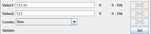
Like multi this will send multiple settings in one command, but for this control each setting is a standard control entry. This is useful when it is required to combine more than 3-4 settings in one command, i.e. when multi gets to large.
It will disable the set button on the selected controls.
It supports the following standard controls: number, numberInt, numberDual, text, combobox and multi
It cannot be used inside selector controls or use controls covered by a selector.
It will collect any :write: from the used controls and combine them to one long string, before using its own :write:
The :read: is not affected and must be defined in each control to initialise it, :read: in the set control is not used.
Code:
#cmdSetup set Update
:write: cmd
control1 control2 page.control3
delimiter
The delimiter is a optional string, use \x20 for a space
Control separator

This control draws a line across the setup form, this can be used to separate groups of controls. A name must be present, but is not used (A - can be used).
It supports the :color: tag
There can optionally be one line of arguments with:
- weight: How thick to make the line (Ignored on type raised/sunken)
- width: How long to make the line 100=100% of width
- type: Line type, default is Solid.
| Solid: |  |
| Dual: |  |
| DashedShort: |  |
| DashedLong: |  |
| Raised: |  |
| Sunken: |  |
| Empty: | Empty space, no lines is drawn. |
Code:
#cmdSetup separator -
2 100 Solid
Control color
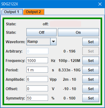
This control do not add a line to the setup, but adds a colored border to the setup form, it will also color the tab for multipage setups. It can be used for each page in a multipage control to match devices with color coded channels.
Like all #cmdSetup specifications it requires a name, it is never shown and can be a dash.
The color is either a name or (r,g,b) format. To find the rgb values a drawing program with a good color selector can be used.
It is also possible to use a :bgcolor: tag, this will change the background color for the page, but it is not recommended.
Code:
#cmdSetup color - Output_2
(250,140,20)
Control selector
By itself it is an invisible control, but it can control visibility of other controls. Invisible controls will not be updated, this means no slow update, even with many hidden controls. The controls can be enabled either based on a SCPI command or based on another control.
The first line with controls will be used for previews and when the value is empty.
Code:
#cmdSetup selector name {page}
expression
value1 control {control {control {control {control ...}}}}
value2 control {control {control {control {control ...}}}}
...
Code:
#cmdSetup selector name {page}
:read: SCPI command
value1 control {control {control {control {control ...}}}}
value2 control {control {control {control {control ...}}}}
...
The "control" is the name of a control, when pages are used use page.name or page. for all controls on that page (The page will not be created then, because all controls are inside the selector).
It is possible to include the same control on more than one selector value.
:update: & :enable: tags on the selector will affect all selected controls.
:update: & :enable: on the individual controls will only be active when the control is selected.
Control updater
This is an invisible control that is used to update other controls at regular intervals, generally it is not recommended to use, except for devices that do not disable local control.
This control only use a :update: tag that must list the controls to update and a single parameter line with one value that is the time in seconds between automatic updates.
Code:
#cmdSetup Updater update
:update:Out1 Out2 Out3 Out4 Out
0.5
A generic interface
This is a interface to use from scripting that is supposed to be mostly independent of selected device, making it easy to swap between different devices of the same type in a test setup. It can be used after an = sign or in expressions. There is a special test form in the "Popups" menu.
There are 3 primary groups of commands:
- set... : Set a configuration parameter.
- get... : Get a configuration parameter.
- read... : Read a value.
In addition some support function will also be defined:
- name... : Column name for read value.
- unit... : Unit name for read value.
The ... is what to set/get/read, it will typically be:
- Voltage: A voltage, either a set point for get/set or actual value for read.
- VoltagePP: A peak to peak voltage, this is typically used for oscilloscopes and frequency generators.
- Current: Some current, either a set point for get/set or actual value for read.
- Power: Some power, either a set point for get/set or actual value for read.
- Resistance: Some resistance, either a set point for get/set or actual value for read.
- Capacity: Some capacity, either a set point for get/set or actual value for read.
- Temperature: Some temperature, either a set point for get/set or actual value for read.
- Energy: Some energy, either a set point for get/set or actual value for read.
- Value: Generic value, used with multimeters for all the different value types it can return.
- Amplitude: A amplitude, usual a voltage, this is used for function generators.
- Offset: A offset, usual a voltage, this is used for function generators.
- Frequency: A frequency, this is used for function generators and oscilloscopes that measures frequency.
- DutyCycle: A duty cycle, this is used for function generators.
- OVP: Over voltage protection, when this setting is reached the device will usually turn output off.
- OCP: Over current protection, when this setting is reached the device will usually turn output off.
- OPP: Over power protection, when this setting is reached the device will usually turn output off.
- On: Used to turn the output on/off or check output status, values must be 1 for on and 0 for off.
- Waveform: Waveform of a function generator, this is not a number, but a text.
- Mode: Select mode, if a mode menu and #askMode exist set/get is generated automatic.
- RemoteSense: Enable/disable remote sense, values must be 1 for on and 0 for off.
- Coupling: Selecting between AC and DC coupling typically on oscilloscopes.
- BW: Define bandwidth typically on oscilloscopes.
- Termination: Define input termination impedance typically on oscilloscopes.
- MathDefinition: Define some math on a device, this function expect a string parameter.
- Relay: Turn a relay on or off, they are numbered from 1 and up.
- Relays: Turn all relays on/off according to a bitmask, bit 0 is relay 1
- Inputs: Returns all inputs in a single word, bit 0 is input 1
For settings that is meant to limit the above value add min/max before the name, i.e. a SetMaxVoltage will set a value that prevents setVoltage higher than that. This only works for devices with native support implemented, TestController do not have any code to enforce it.
The call format for a function is one of:
Code:
setPower(device,value)
getPower(device)
readPower(device)
namePower(device)
Where device is a string with the device handle and optionally a ":channel" in the same string. Channel is used for multichannel devices and defines what channel to use, when not included 1 is assumed. Value is the desired value and is usually a number (Waveform and Mode are strings).
Code:
=readVoltage("QPX1200")

In log window:
;; 11.995
Code:
=readAmplitude("sdg2122x:2")

In log window:
;; 2.0
Definition of set...
Code:
#interface set... SCPICommand (value)
#interface set... SCPICommand (channel) (value)
The (value) and (channel) can contain expressions when needed.
Code:
#interface setVoltage voltage (value)
#interface setFrequency C(channel):BSWV FRQ,(value)
#interface setOn c(channel):outp (getElement("off on",value," "))
Definition of get...
Code:
#interface get... SCPICommand
#interface get... SCPICommand (channel)
:readmath:
:readformat:
This function gets a setting from the device. It is possible to use :readmath: and :readformat: to get the value into a acceptable format. In a few cases a :string: tag can be needed to allow string handling and returning a string value.
Code:
#interface getVoltage voltage?

#interface getAmplitude c(channel):BSWV?
:readmath: getElement(getMatch(value,"AMP,[^,]*,"),1,",")
:readformat: u
Definition of read...
Code:
#interface read... column
#interface read... column column...
The definition of read is very easy, because it uses the same reading as "current values" and logging, i.e. the "#askValues" command and only the actual index of the value must be specified. For multichannel devices multiple indexes must be listed, one for each channel. The first value the device returns is numbered 0.
The read definitions also defines a name... command that can be used to get the column name for the value from the actual device.
The #interfaceType definition
In addition to the actual interface calls it is also possible to assign a type to the device, this is used as a way to get a generic device from a script. This work likes this:
Code:
=var ps=getDevice("PS");
=setVoltage(ps,10);
=setCurrent(ps,1);
This means find the first power supply on the loaded device list and assigns its handle to ps. Now the different interface function can be used to setup parameters. Use getDevice("+PS") to get the second power supply or getDevice("PS:3") to get the 3 channel of the first power supply with 3 or more channels.
For this to work each device must have a #interface type listing the possible types support be this device:
Code:
#interfaceType PS
#interfaceType PS PS:2 PS:3
First line is for a single channel power supply, second line is for a multichannel power supply. A device may list more than one device type.
Device types:
- PS: Power supply
- ACPS: AC Power supply, usually a generator that can deliver 120/230VAC
- DMM: Digital multimeter
- BMM: Bench multimeter, this is guaranteed to have electronic control of ranges with setMode(). A BMM will usually also list a DMM type.
- ARB: Arbitrary waveform generator
- LCR: LCR meter
- Load: Electronic load
- Power: Power meter
- Osc: Oscilloscope
- Relay: A controlled switch
- Servo: Servo driver controlling a motor/servo
- Charger: Battery charger device
More will be added over time.
Miscellaneous tags
#author
This tag is used to add information to the about popup. All text after the tag is place on that popup, together with the name of the driver it is in.
It is a way to get credit for defining definitions for devices.
#mayModifyMode
Each tag list the start of a command, if there is a match to any command typed from the Command screen the current column layout is invalidated and a new one will be created using the askmode function.
#notes
This tag will add a small "view" button to the device list and pressing this button will show any text after #notes until the next # tag
This can be used to write about required settings on the device, limitations in the device definition, etc.
Only one #notes is supported, but as stated above it can be multiline.
#noteImages
This tag will add a small "view" button to the device list and pressing this button will show any images that is listed after the tag. The images will usually be stored on my server.
This can be used to show imaged with switches/jumpers that need to be set a specific way or in some cases a image of the device can be useful.
#help
Specifies the name of a file with help to the SCPI commands, this file is placed on my server and downloaded when the device is loaded. A local backup is kept in ...\Documents\TestController\Settings for offline conditions.
The device name is used as default file name when no #help tag is present.
#helpurl
This URL is used when F1 is pressed on a mode or setup popup.
It can link to a page describing how the device work in test controller (If anybody writes this type of pages I can host them).
It can also link to the manufactures page about the device or a manual for the device.
Using DEVICEIP for IP address/name will link to the device itself, if it uses a socket or LXI protocol.
The Other popup
This button/menu was added in V1.65, it access some device configuration and works very differently from the "Setup" popup, because it uses scripts to handle the functions. All functions defined here will run in the background, i.e. they do not block TestControllers user interface, but it is usually a bad idea to do other operations on the device will a transfer is in progress.
This requires a couple of entries in the configuration file.
#otherList
This entry is used to define the other menu, the menu will only be shown if a script here defines it (or a screendump definition exist). What is has to do is assign text lines to a array called menuItem.
This can be done two ways:
menuItem[0]="item1";
menuItem[1]="item2";
menuItem[2]="item3";
or
menuItem=array("item1","item2","item3");
There must not be any missing items in the array.
Each item must end with an extension, these extensions matches file extensions and defines what type of function is required:
.bmp .png .jpgWill assume it is image related.
This means a entry defined as: menuItem[0]="item1.png"; will be show as a menu entry called "Image: item1"
.csv Will assume it is a list of measurement data that can be transferred to the table is TestController.
This means a entry defined as: menuItem[0]="item1.csv"; will be show as a menu entry called "Data: item1"
.xxx Will assume it is a command (These are usually best put in the Setup popup), no data is accepted by TestController
This means a entry defined as: menuItem[0]="item1.xxx"; will be show as a menu entry called "item1"
Any other extension (Please use .txt) will assume it is a list of information that must be shown as text.
This means a entry defined as: menuItem[0]="item1.txt"; will be show as a menu entry called "Text: item1"
All menu entries will call a program at another tag depending on the extension. If there are more menu entries that calls the same tag it is possible to use the name variable to see the name of the menu entry that called the tag.
#otherImage
This function must fetch the named image (Menu entry name is present in variable name) and send it to the image viewer. The coding here will often be limited to using deviceReadBytes() and addImage().
For more complex downloads native code must probably be added to TestController.
#otherData
This function download data and adds them to the table page, replacing anything already in the table. This can work two ways:
- Download data in .csv format (Probably using deviceReadBytes()) and just dump them to the table using the tableAddCSVText() and binConvString() function.
- Download data in any other format, this means there must be code to setup the table. This will often be a lot of deviceRead() and using tableInitHeader() for the header and tableAddRow() for each data line.
In both cases it is also a good idea to show a progress bar, this must be coded with popupShowProgressAsync() and popupShowProgressSetPosition()
It may be necessary to use modeColumnNames() to get the correct column names for a device.
#otherFunc
This can be used to do more advanced functions on the device where a script is required or to clear the log on devices where that requires a lot of keypresses.
Use the deviceWrite() function for writing commands and deviceRead() for reading values.
#otherText
This is for data that must be showed as text, it can be logged data that is unrelated (a entry saved each time a button is pressed) or it could be some other information from the device. For column based data it is a good idea to use a tab ("\t") separator, this allows the data to be easily copied to a spreadsheet.
The script must collect all the data in a string and return it when it is finished. This can be done by writing the variable name last in the script. The return data can also be collected with "print()" statement, these are combined and used as a function return value.
If it takes some time to collect the data it is a good idea to show a progress bar, this must be coded with popupShowProgressAsync() and popupShowProgressSetPosition()
Examples
I will not list examples, but instead list some definitions that uses these functions:
Keysight344xxA.txt can fetch a screen dump and access the internal flash drive for saved screen dumps and csv files.
KeysightU1461A.txt Download log data from some multimeters as either text or csv data.
Creating multiple devices from one configuration file
With similar devices it is possible to make many device definitions from one configuration file.
#meta
Mark a definition to not be include in the device list, but only used as the basic for other definitions. This type of definition is referred to by their filename (Without path and extension).
#metadef
Create a definition based on another definition, either a real definition or a #meta definition. It is possible to replace some tags, change parameters and remove tags, but it is not possible to add new tags. The original definition must contain everything needed.
Code:
#metadef
#metadef filename without path and extension
#metadef device name
The #metadef tag can be used 3 ways, without a name means it will expect a #meta definition in the same file and then with either the filename of a file with a #meta tag or the device name of a existing device configuration.
After the #metadef there will often be a couple of lines to modify the definition, but for definition in the same file there may be one #metadef without any modification instruction.
#idstring, #name, #handle, #port, #driver, #baudrate, #subdriver, #baudrate, #subdriver, #usbvendor, #eol, #verifydevice, #help, #checksum
These tag after a #metadef will replace the corresponding tag in the original definition.
Code:
#metadef
#idString ITECH Ltd, IT8511A,
#name Itech IT8511A+
#handle IT8511A
#replace
Code:
#replace #tag params
...
Replace all settings between a tag and the following tag.
Code:
#replace #cmdSetup indicator State
:read: test?
off 0 red
on 1 green
#remove
Remove section, both line with #tag and all lines until the next #tag
Code:
#remove #cmdSetup indicator State
#removeline
Remove any line that starts with the text after the tag.
Code:
#removeLine 60A
#removeLine 120A
#removeLine 240A
#replacetext
Replaces the first word after the tag with the second word after the text. This makes it possible to adjust limits and other values in the original definition.
Code:
#replaceText MinVoltage 0.1
#replaceText MinResistance 0.05
#replaceText MaxCurrent 30
#replaceText MaxVoltage 150
#replaceText MaxResistance 7500
#replaceText MaxPower 150
#sections
This tag is used together with #metaSection in the actual definition to include or exclude larger blocks of lines. Only one #sections tag is used in each #metadef section.
Code:
#sections
#sections dual
#sections dual 20A
The above are examples of section specifications in the #metadef part
Code:
#metaSection dual

#metaSection dual 20A

#metaSection
In the actual definition the #metaSection tag is used. The first one will be include in any #metadef/#sections that specifies dual, the second one will only be include for #metadef/#sections that both specify dual and 20A. The last is always included and is used to end a conditional (#metaSection) section.
Note: #metaSection is only valid in #meta definitions, a normal definition will always fail to load when containing a #metaSection tag.
#metaDebug
This is a debug tag that can be placed on the line after a #metadef tag, this will list all performed modification instructions on the console output (This requires starting testController from the command line).
Code:
#metaDebug
#metaDebug save
Adding a save tag after the #metaDebug will save a file with the processed definition
Protocol is nearly SCPI, but there is a few issues (SCPIx)
This driver is designed to handle minor non-scpi details, in some ways it is similar to "Ascii" driver, but as default commands are passed to the device and they do not support all the same configurations.
See Difference between the 3 SCPI/ascii drivers (SCPI, SCPIx, Ascii) for a explanation of the different ascii drivers.
Some devices requires the commands to be in uppercase, this tag will handle it:
Some older device may return a prompt on the serial connection, to get rid of it use:
Code:
#removePromptChars count
This will remove count characters after each command and also wait until the prompt is received or timeout occurs.
This function will be disabled on GPIB interfaces.
Transmit a command and optionally receive an answer.
Code:
#scpiCmd name tx cmd
#scpiCmd name txrx cmd
#scpiCmd name? txrx? cmd
#scpiCmd name? txrx? cmd
#scpiCmd name? txrx2? cmd
#scpiCmd name? txrxn? lines cmd
#scpiCmd name? txrxnBin? bytes cmd
#scpiCmd name? txrx1Bin? cmd
#scpiCmd name none
#scpiCmd name? none?

#scpiCmd name tx cmd (value)
#scpiCmd name txrx cmd (value)
#scpiCmd name? txrx? cmd (value)

#scpiCmd name #pgm#
#scpiCmd name? #pgm#
Use (value) to insert parameters from the "name" command. It is possible to use value multiple times and it is also possible to use an expression inside the brackets.
A number or n in the command lines means multiple lines, except with bin where it means bytes (Up to 8, answer is return as a number).
The until functions need a expression to check the "value" for the correct answer, all means all answer up to that point is combined.
The none functions are used together with :setvar: and a local variable. With none? use ":readmath: definedVariableName" to get contents of variable.
Reading a binary value from a device:
Code:
txrx1bin? command (Use \n at the end).
This command will return a number from 0 to 255, with ":readmath: int(value)&0x??" bits can be tested. This command is typically used in #scpiCmd definitions.
The most significant update is support for redefining commands:
Code:
#scpiCmd name definition
These definitions support :readmath: and :setvar: tags.
The command will replace name with definition before transmitting it to the device. Parameters must be added with (value)
This instance of #scpiCmd also support the [xxxx] delay specifications.
Code:
#scpiCmd name #pgm#
#scpiCmd name? #pgm#
The string #pgm# means the rest of this definition is a calculator script, it can use deviceWrite() & deviceRead() to access the device, but there is no requirement it must access the device. This definition type is only designed for fairly advanced usage. To see more about calculator script see here
Any parameters can be accessed as value (at least until deviceWrite() or deviceRead() is called), it shares variables with :setvar: and :readmath:, this means it is possible create and use variables between this script and other scripts in other part of this definition. The deviceWrite() and deviceRead() functions can only access the actual device and it is legal to use a empty handle (i.e. "");
Two variables describing the connection are available:
portType is the connection type: None, Serial, Socket, LXI, USBHID, GPIB, UDP
portAddress is the value in the address field.
Example of handling a init command that is not supported in GPIB mode:
Code:
#scpiCmd MyInit #pgm#
if (portType!="GPIB")
  deviceWrite(handle,"SYST:REM;");
endif;

This command can then be used:
 #initCmd *RST;MyInit;
This driver is used for the Korad_KAxxxxP supplies.
User supplied stuff
Some explanation/hint on making device definition: User config hints
Script to pretty up device definition and check a definition: Python script
Script to generate a second channel from channel 1: Python script