Test of DC-DC 10A 6.5-60V to 1.25-30V
Official specifications:
- Input: 6.5V-60V
- Output: 1.25V-30V(adjustable)
- Efficiency: 97%(Max)
- Module: 75*21*16mm / 2.95*0.82*0.63"
- Operating Temperature: -40°C ~ +85°C
- Load Capacity: 10A(Max)
I got this module from ebay dealer: industry_mall

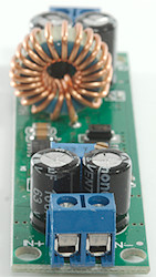
The module arrived in a anti static bag.
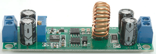
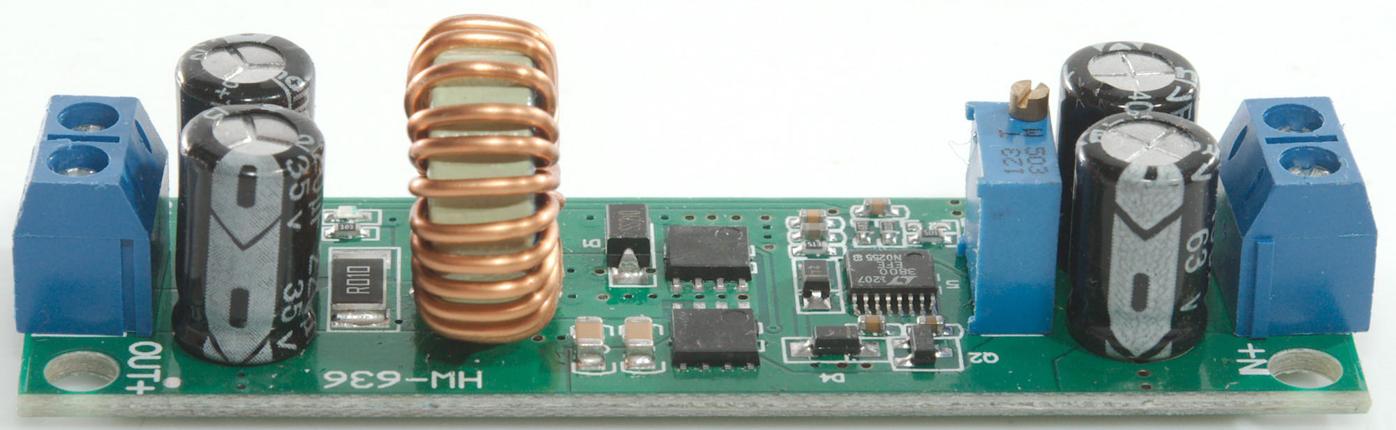
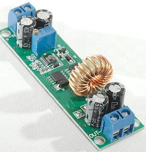
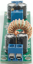
A open module with screw terminals for input and output and a trimpot for voltage adjustment.
Testing
I use automatic tests to perform a lot of tests on this type of module, for the first test series I adjusted 5V output with up to 60V input and up to 10A output current, this matches the specifications. Due to an error my supply was limited to 3A. I then started the test and vent somewhere else (The test takes a couple of hours).
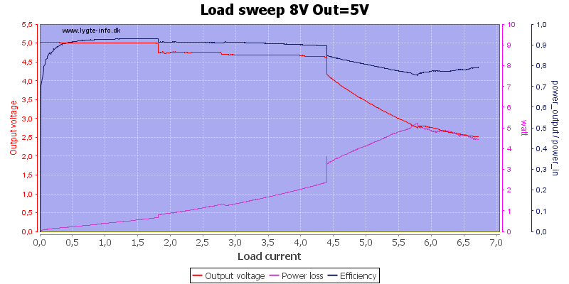
The 5 volt output did not last long, this is probably due to the trimpot and not the regulation. At 4.5A I hid the input limit.
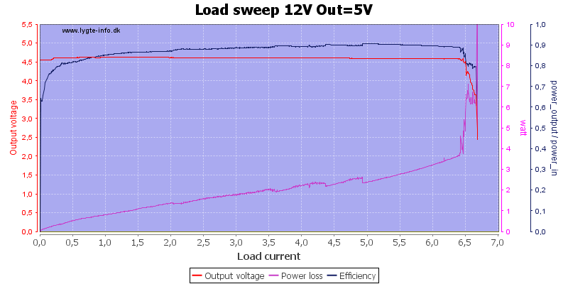
Increasing the input voltage to around 12V made it possible to maintain output up to 6.5A before hitting the input limit.
The efficiency is around 90%, not anywhere near best case specifications of 97%.
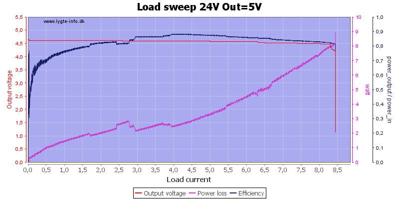
With 24V in the output can deliver 8.5A, but I am loosing 8W in the module and it do not have a heatsink, this looks bad. At this and higher voltage the input limit will not affect the output.
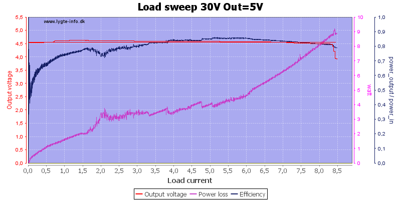
It is about the same at 30V input.
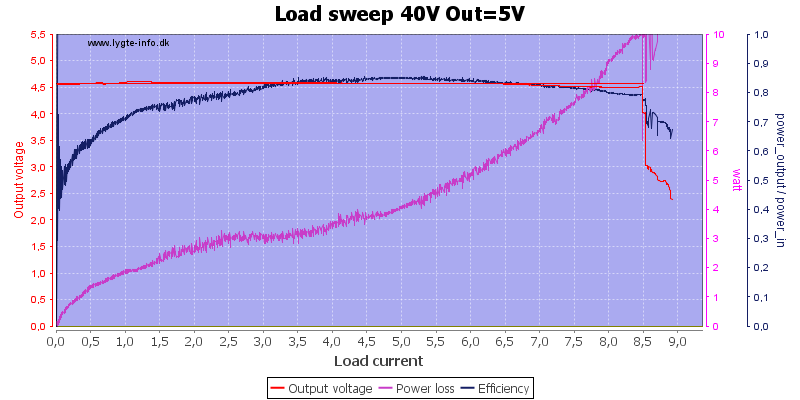
With 40V input the power loss is going higher.
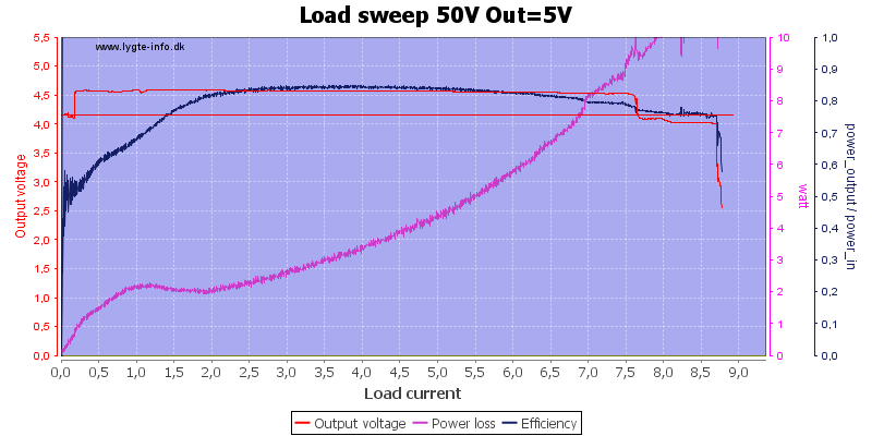
At 50V input the power loss is above 10W without a heatsink.
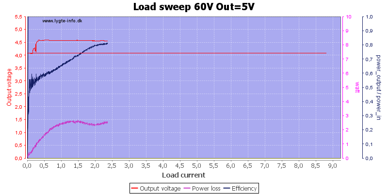
At 60V I reached 2.5A and the module died. This prevent me from doing more test!
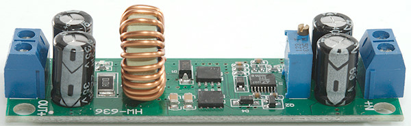
A closer look at the circuit
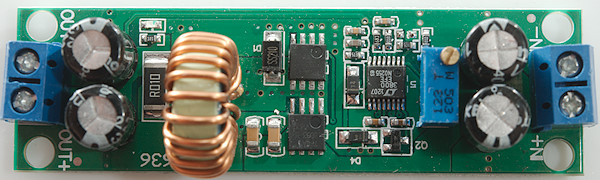
The circuit uses a buck converter IC (U1: LT3800 Max: 65V) and two transistors (2x TPCA8053: 60V 15A/45A 13.9mOhm). This is not a 60V converter, I would never rate it above 50V. It do not look like there is any over temperature protection.
After the inductor is a current sense resistor (R010: 10mOhm)
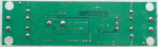
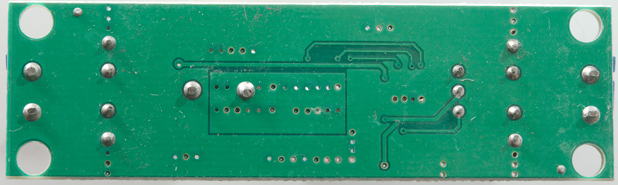
There is nothing, but a few solder pads on this side. The solder pads means it cannot be mounted on a heatsink.
Conclusion
This was a considerable shorter test than I had expected, if I had checked the parts first I would not have done the 60V test.
Neither maximum current nor maximum voltage is correct and the voltage adjustment is difficult to adjust and as can be seen the output voltage changed during usage. The efficiency is also lower than specified, but that is probably because I use 5V output, you need 24V input and 12V output and about 2A load for best efficiency. The module may be able to handle 3-4W loss, but much more and it needs heatsink and/or fan.
I do not really like this module, if not for the bad voltage adjustment it could be used at lower power level.
Notes
The converter was supplied by a reader for review.
Index to other tests