Converter DC-DC 10A 8.5-48V to 10-50V 250W
- Module name :250W boost constant current module
- Module properties: non-isolated step-up module (BOOST)
- Input voltage: DC 8.5V-48V
- Input current: 10A (MAX) exceeds 8A please enhance heat dissipation
- Quiescent current: 10mA (12V liter 20V, the output voltage, the higher the current will increase too quiet)
- Output voltage: 10-50V continuously adjustable
- Constant range: 0.2-8A
- Temperature: -40 to + 85 degrees (ambient temperature is too high, please enhance heat dissipation)
- Operating frequency: 150KHz
- Conversion efficiency: up to 96%
- Overcurrent protection: Yes.
- Input reverse polarity protection: Yes.
- Installation: 4pcs 3mm screw holes
- Connection method: Connection Output
- Module size: 70mmx36mmx13mm
- Single module: 50 g
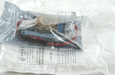
The module arrived in a antistatic bag in a envelope

Measurements
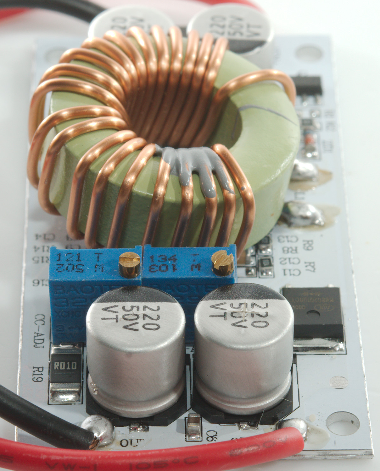
- Voltage adjustment works fine, it is fairly easy to adjust with 0.1V precision.
- Maximum output voltage can be adjusted above 50V, this will damage the capacitors.
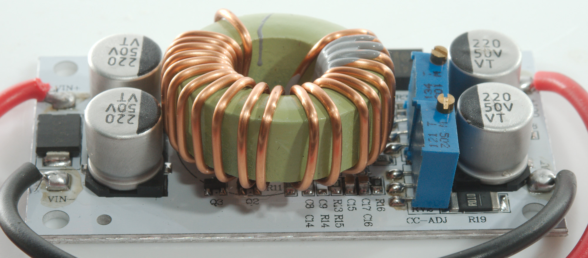
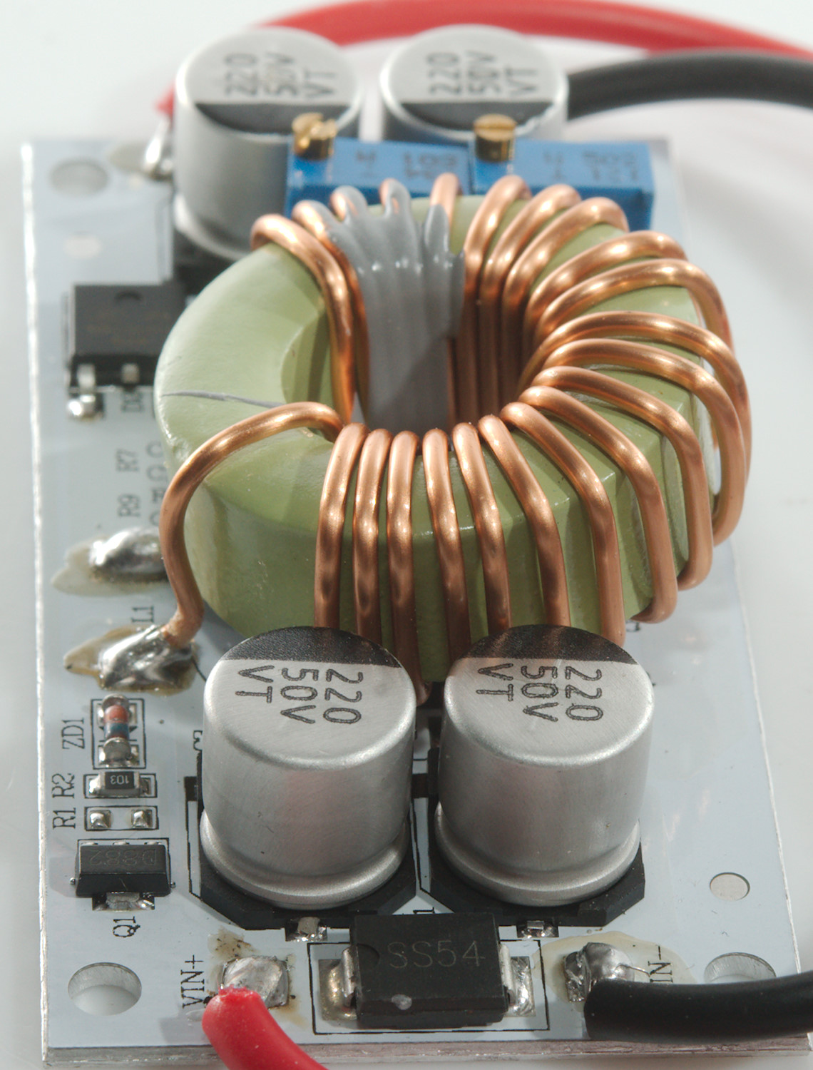
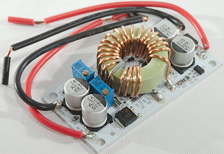
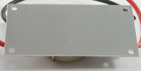
- Circuit board is aluminium
- Size: 70.0 x 36.0 x 17.8 mm
All the test is published here
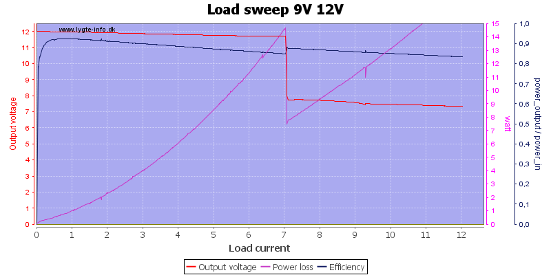
This is about the minimum output voltage, it maintain voltage nicely up to 7A, then drops to below input voltage and continues to supply current, this is standard boost regulator behaviour. I do not expect the over current protection to help with this.
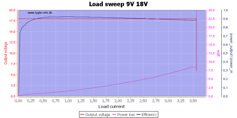
The boost regulator destroyed itself when I tested with 18V output and a power source limit of 15A. I changed to 8A limit and used a second module. Boosting from 9V to 18V means a bit below half current in output.
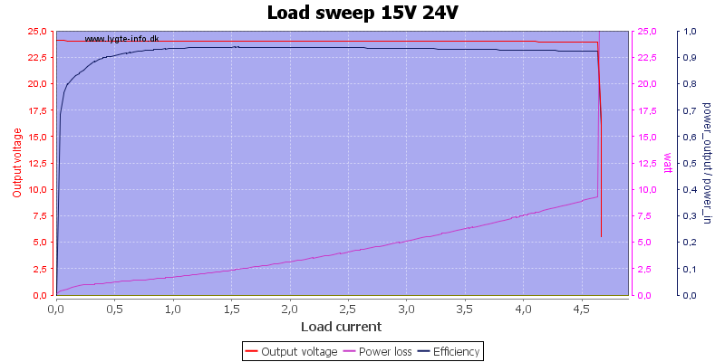
Boosting 15V to 24V, here the efficiency is good
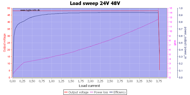
Boosting 24V to 48V also looks good, generally the module works fine as long as the current is limited.
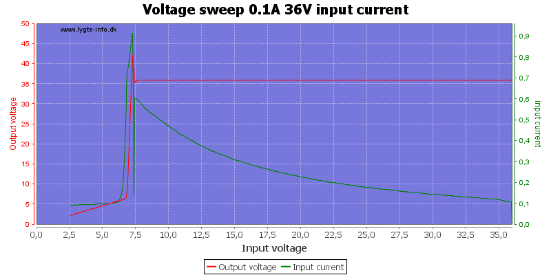

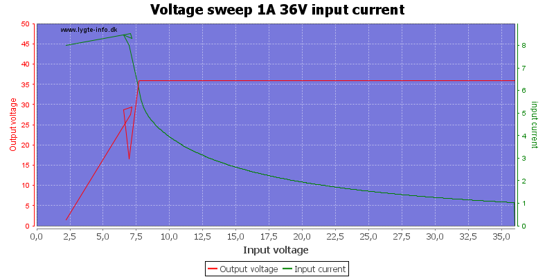
A low load and and a voltage sweep from 36V down to 0V, the module mains output to about 7.5V where it do some strange stuff including higher output voltage!
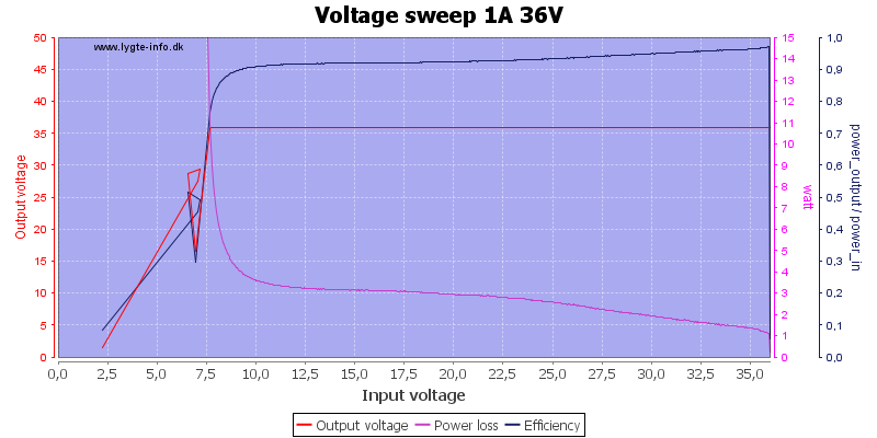
With 1A load it again maintains voltage down to 7.5V, where the current increases slightly above 8A, this kills this module!
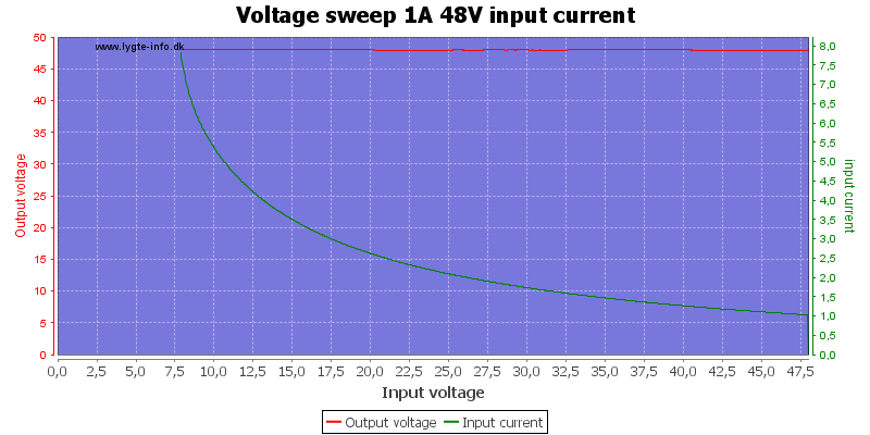
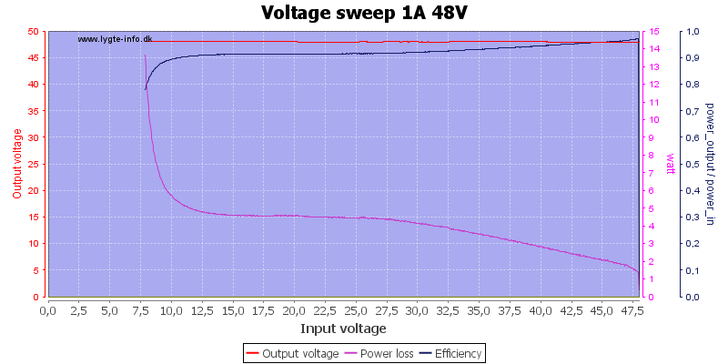
I did get a curve with 48V output and 1A load, here it worked fine.
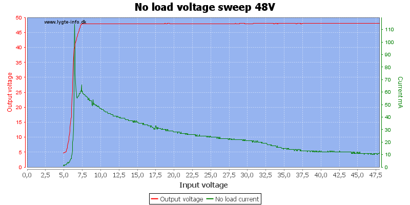
Without load the module must still keep the boost converter running, how much power it uses depends on input and output voltage. Worst case looks to be about 60mA.
With two dead modules I stopped testing this converter
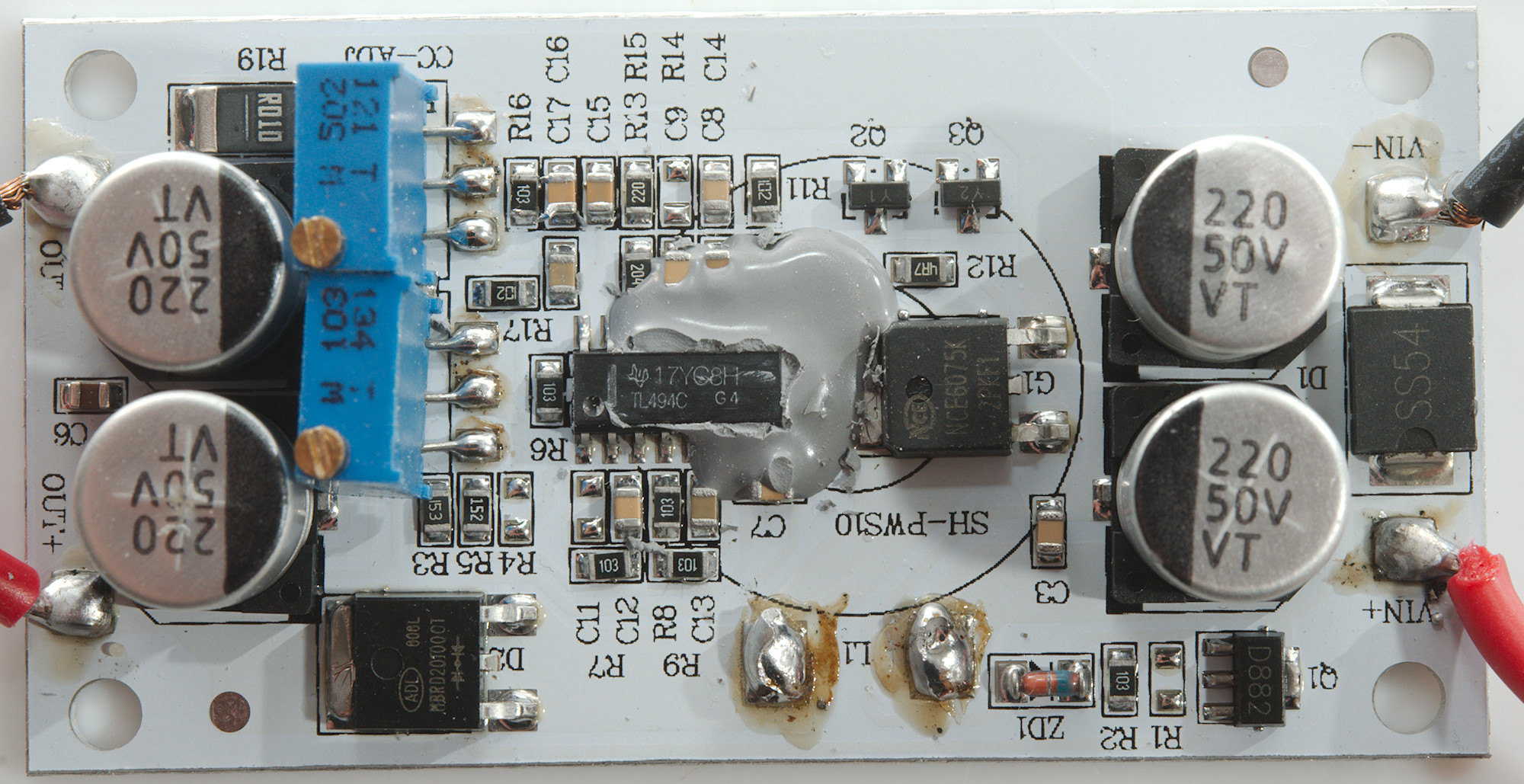
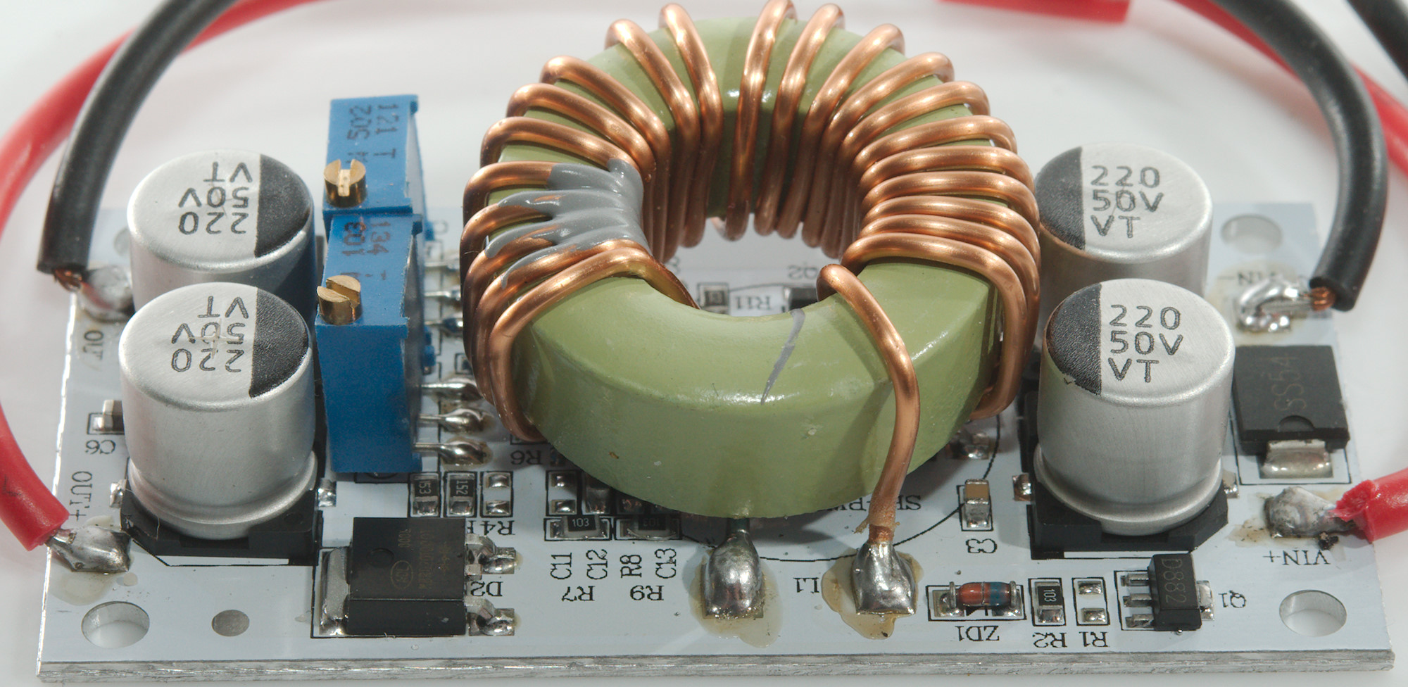
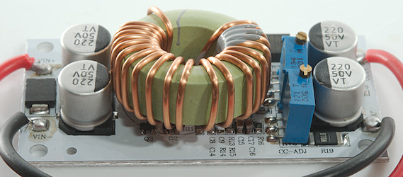
A closer look
The diode at the input is mounted in reverse polarity and will short the input if polarity is swapped, both input and output capacitors are in parallel, i.e. the maximum voltage is 50V.

With the module dead I had no problem with removing the inductor, the mains switcher controller is a TL494C and the switching transistor is NCE6075K. The zener diode (ZD1: 15V) and nearby transistor (Q1) is the voltage regulator for the switcher IC, it is only rated for 41V.
In both modules it is the switching transistor that died.

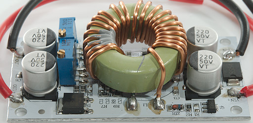
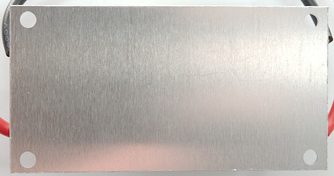
This aluminium bottom makes it easy to mount the converter on a heatsink and with up to 10W loss in the module it may be necessary.
Conclusion
The module works fine to boost voltage, but the over current protection and maximum current is not something to depend on.
But without noise and on/off test I will not conclude anything about the modules, except they are not that robust.