Oscilloscope Aarontek DSO338
This is a small oscilloscope with the most common functions.
Official specifications:
- Analog band width: 30MHz
- Maximum real time sampling rate: 200MS/s
- Vertical sensitivity: 50 mV/div ~ 200 V/div
- Horizontal time base range: 100mS/div ~ 125nS/div
- Maximum input voltage: 40 V (1X probe), 800 V (10X probe)
- Storage depth: 128KB
- Input resistance: 1M
- ADC precision: 8bits
- Coupling mode: AC/DC
- Trigger mode: Single, Normal, Automatic
- Trigger edge: Ascending/descending edge
- External trigger voltage 0 40 V
- Display: 2.4 inch - IPS - 320*240
- Power supply: 3000 mAh lithium battery
- Size: 90 x 70 x 28 mm
- Weight: 200g
It arrives in a brown cardboard box.
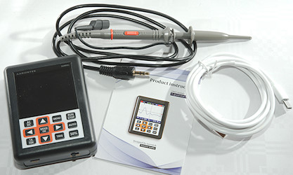
Inside is the oscilloscope, a probe, a usb charging cable and a instruction sheet.
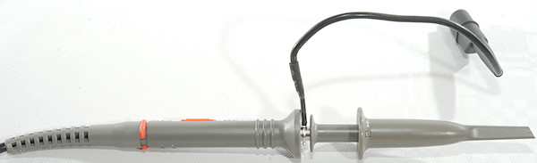
Lets first take a look at the probe.
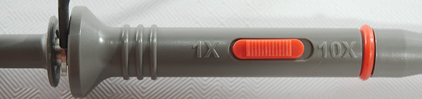
It has the usual 1x and 10x setting and even a color coding ring for multichannel scopes, it is not much use here.
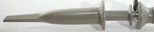
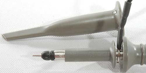
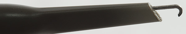
The tip is fairly standard for oscilloscope probes.
With a ground lead with alligator clip
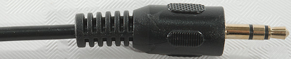
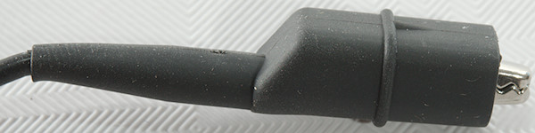
What is non standard is the connection to the oscilloscope, it is with a mini jack plug, not BNC.
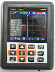
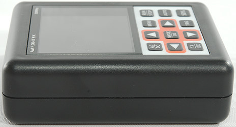
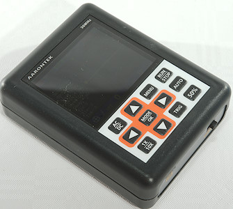
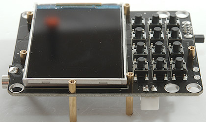
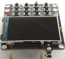
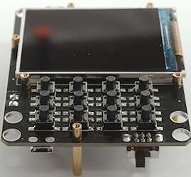
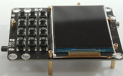
The oscilloscope is a box with screen and keys on the top side.
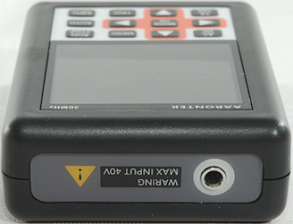
The mini jack input is at one end.
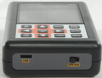
On-off and USB charging connector is at the other end.
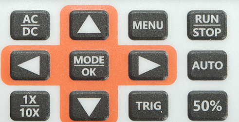
All user interface is with a couple of buttons:

 : Adjust timing, move curve, move trigger voltage, navigate menu.

 : Adjust voltage, move trigger position, select up/down trigger, navigate menu.
- AC/DC: Switch between AC and DC coupled.
- 1X/10X: Switch between 1X and 10X, this will affect voltage ranges.
- Menu: Show or hide the menu.
- RUN/STOP: Freeze/unfreeze the curve, also used with single trigger to trig the scope.
- Mode/Ok: Change mode for arrow keys (time-voltage/Curve location/Trig) and used for accepting settings in menu.
- Auto: Auto adjust voltage/time for a decent curve.
- Trig: Trigger mode: Auto, Single, Normal
- 50%: Move trigger to 50% amplitude on curve
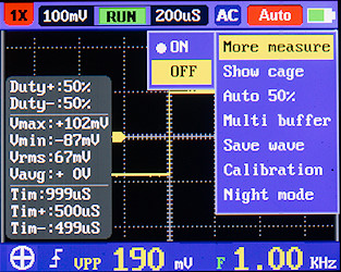
- More measure: Enable/disable the measurement popup.
- Show cage: Usual called show grid and enables/disables the grid.
- Auto 50%: In auto trigger mode automatic move trigger to 50% amplitude on curve.
- Multi buffer: How many curves to average for the display.
- Save wave: Save or view captured waveforms, many keys change functions when in waveform view.
- Calibration: Zero the input without a probe connected.
- Night mode: Switch between white or black background.

Welcome screen.
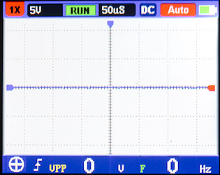
This is daylight mode screen.
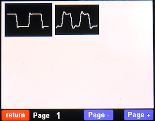
A look at saved waveforms, it is possible to use the arrow keys to move around and AC/DC, MENU and RUN/STOP is "soft keys", i.e. the functions listed at the bottom of the display. 1X/10X and 50% are delete keys.
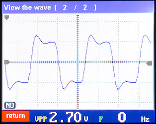
Viewing a saved waveform, the time and voltage setting is missing from this display. The VPP and F values will be saved with the curve, but not the measurement popup. Use arrows to select next.
Testing
- DC input impedance in 10x mode is 9.4Mohm with probe
- DC input impedance in 1x mode is 0.41Mohm with probe
- 3dB bandwidth is around 15MHz, with probe on 1X the input impedance is fairly low!
- Scope time ranges: 125ns, 250ns, 500ns, 1us, 2us, 5us, 10us, 20us, 50us, 100us, 200us, 500us, 1ms, 2ms, 5ms, 10ms, 20ms, 50ms, 100ms, 200ms, 500ms, 1.2s, 2s, 5s, 10s, 20s, 50s
- Time ranges above 1s use a scrolling display.
- The measurement popup is hidden at time settings of 100ms and slower.
- The measurement popup is hidden in normal or single trigger mode.
- In single and repeat trigger mode the trigger point is always at the left edge of the screen.
- At 500ns and faster the curve will always be an average of multiple traces in auto trigger mode
- Input capacitance with probe in 1x: 365pF and 382pF in lowest 3 ranges (Probe is 90pF in 1X mode).
- Input capacitance with probe in 10x: 25pF
- Scope 1x ranges: 50mV, 100mV, 200mV, 500mV, 1V, 2V, 5V, 10V
- Scope 10x ranges: 20V, 50V, 100V, 200V Why no overlap with the lower voltage, that would be useful
- AC coupling is true AC coupling with a capacitor.
- On the mini jack the center ring is not used, probe tip is tip of mini jack.
- When turned off the current draw is around 0.9uA
- When turned on the current draw is around 230mA
- The USB connection is charge only, there is no data connection.
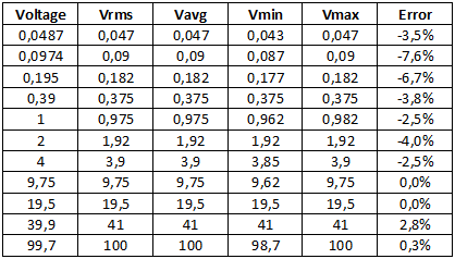
A check of the volt ranges with DC voltage, they are not precise at the lower values, but good enough for most work.
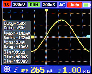
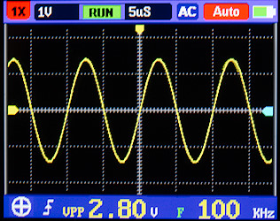
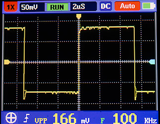
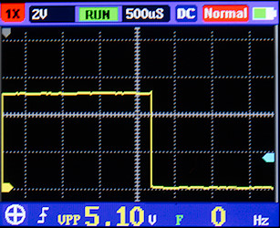
A 1kHz 100mV rms input signal, it looks fine except the RMS calculation cannot handle a square wave.
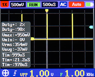
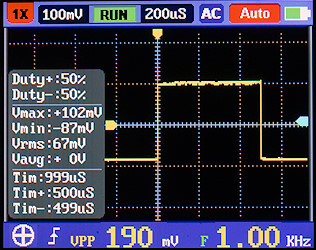
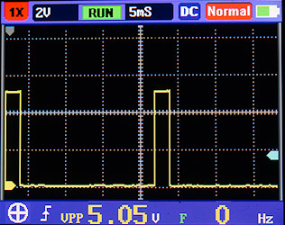
Duty cycle measurement works very fine, here I use a 2% duty cycle at 1kHz and the scope shows it nicely.
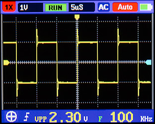
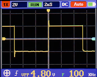
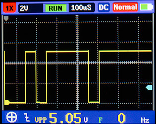
100kHz also looks good, but there is some spikes on the square waves, I will look at them below.
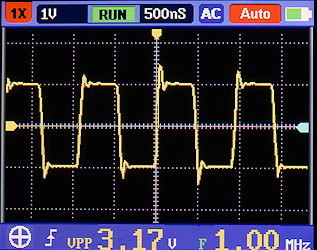
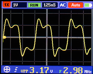
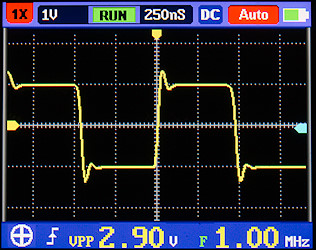
1MHz also looks good, but at 3MHz the spiking is a bit much.
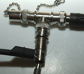
My connection to the function generator was done this way with a termination, but the probe ground lead may be a problem.
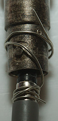
Lets try this instead with very short ground connection (Some probes includes accessories for this type of connections).
The spike is still present, but maybe a bit smaller.
Lets switch the probe to 10X range without telling the scope about it (To avoid it selecting the high ranges). This reduces the spikes a bit, but voltage calibration is not 1/10 (Probes usual has much better frequency response in 10X range).
The manual trigger is always at the left edge of the screen, but level can be adjusted.

Here I try to do a "real" measurement, i.e. checking timing on some neopixel data. This is very fast pulses and the high time must be within some limits to work. I believe the scope is good enough to show it, but not without trouble. The trigger do not fire every time, I had to send the data many times before I got a capture.
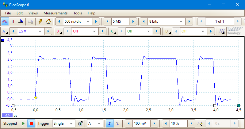
My usual (and much more expensive scope) captured on first try and the higher resolution is a advantage.
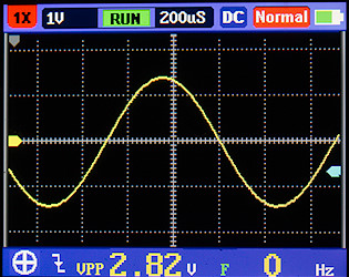
A look at a servo signal, the pulse is 1.5ms long, there is some timing error on the scope. Slowing the timing down to get more pulses and adjusting the pulse with to 2ms also has some timing error, there is exactly 20ms from start of first pulse to start of next pulse.
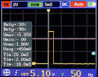
Switching to auto trigger and using the measure menu shows the correct values.
A single character at 9600 baud, it is a "z" with code startbit-01011110-stopbit (lsb is transmitted first). It cannot decode the data or collect more than one screen at a time.
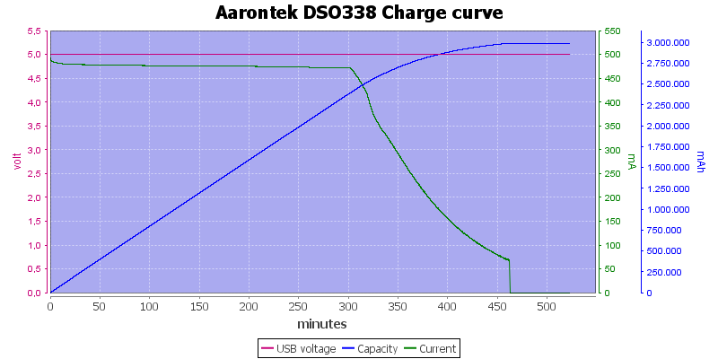
A full charge of the build in battery from USB, it looks like the rated 3000mAh is correct. With close to 8 hours charge time it is not fast to charge, but then the runtime on a full battery is also fairly long with an estimated 13 hours.
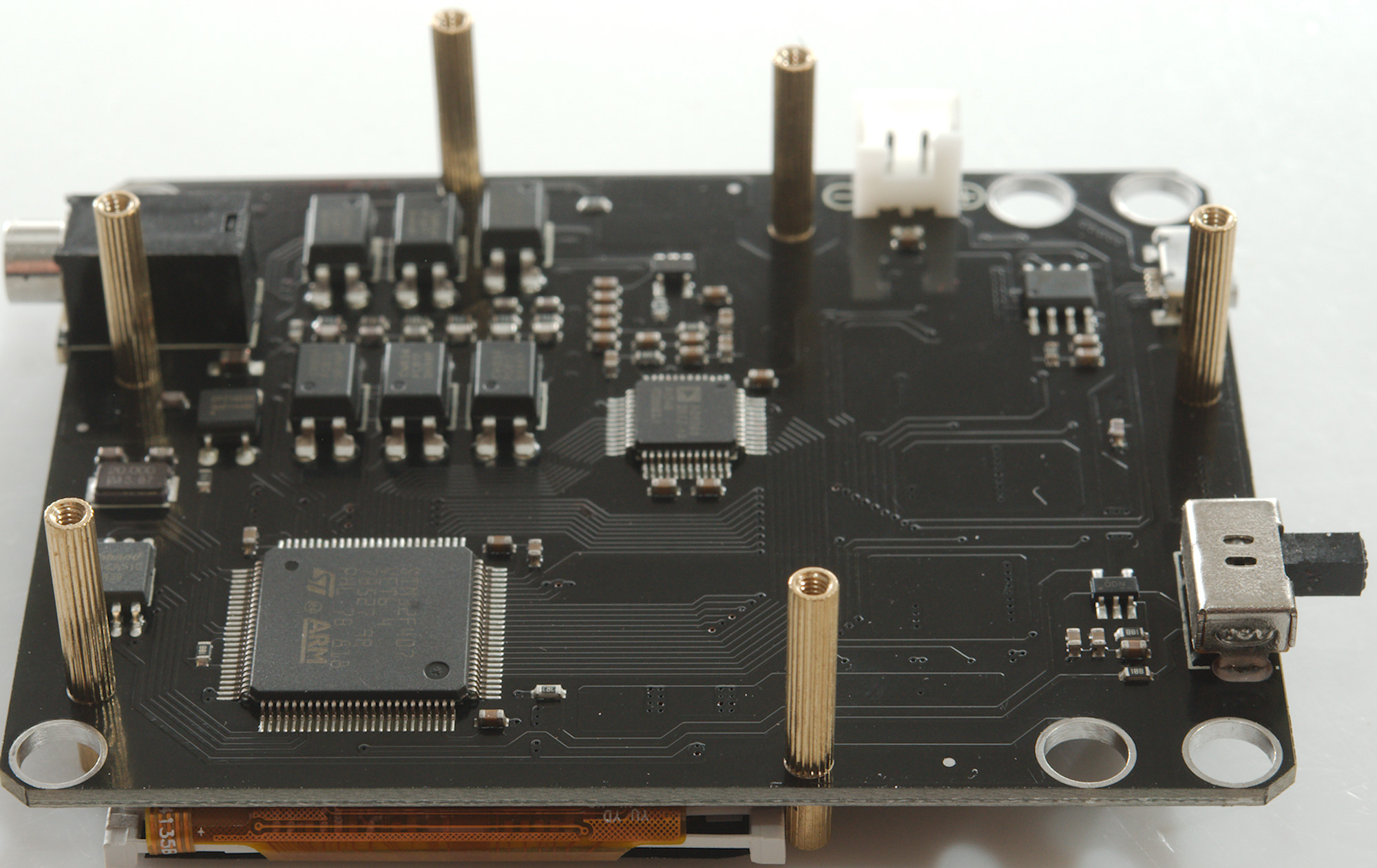
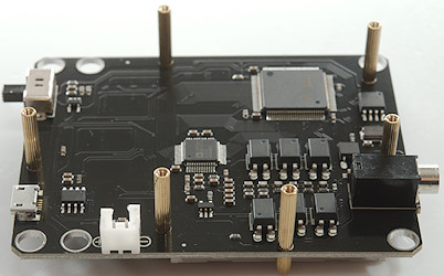
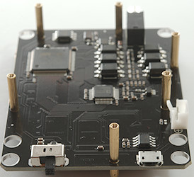
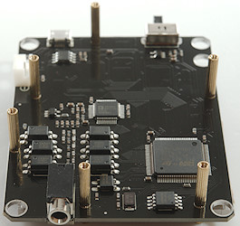
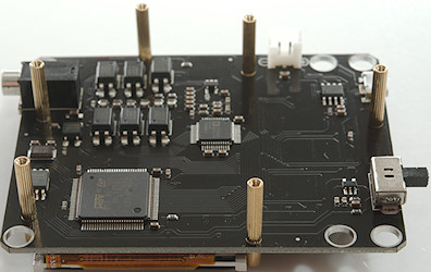
Tear-down
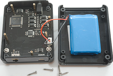
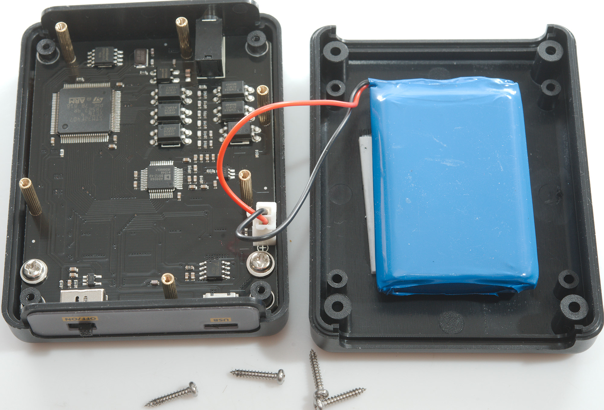
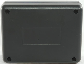
It is easy to open with four screws on the back.
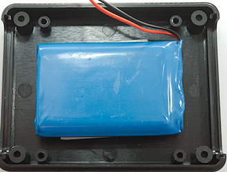
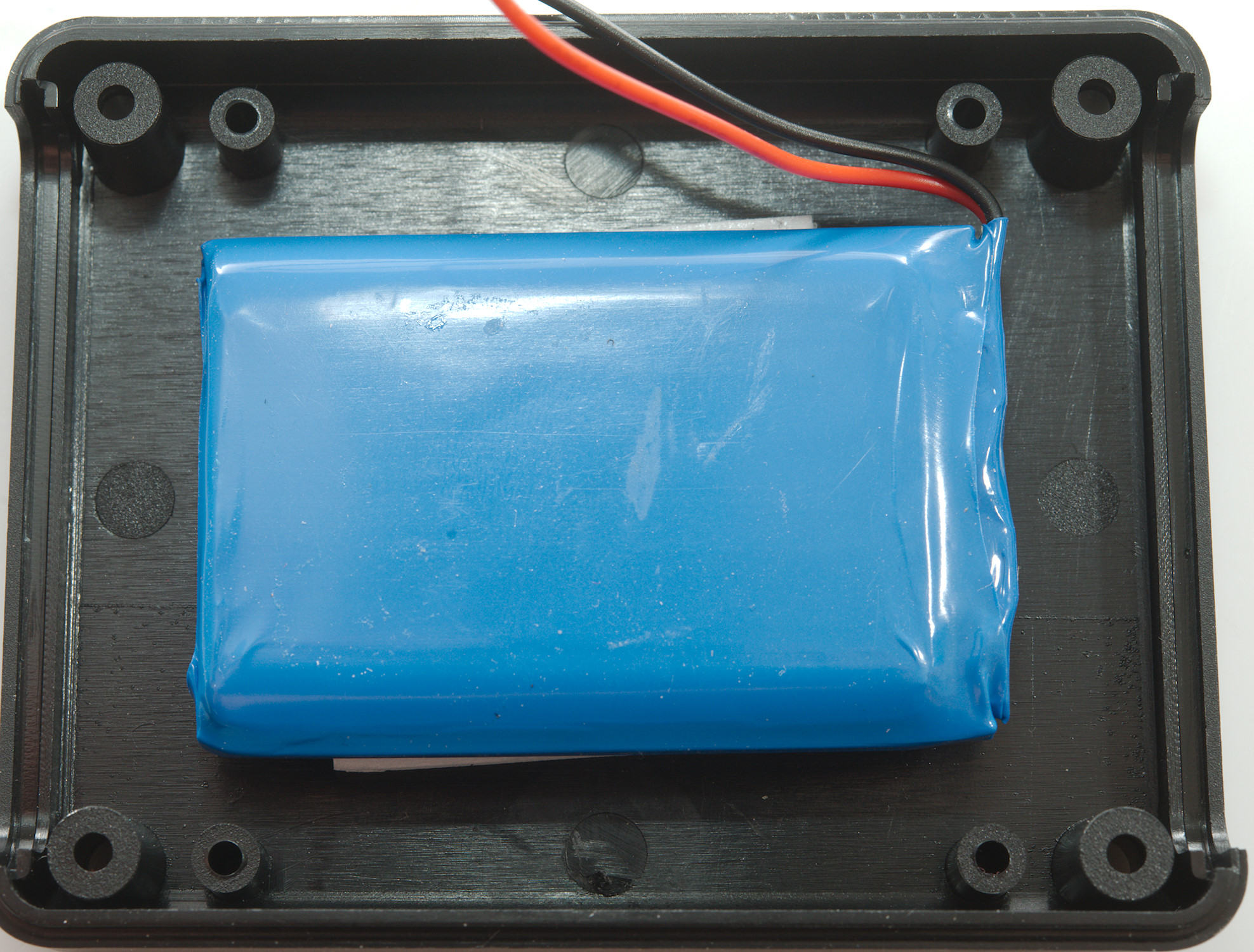
The battery is fairly large and unmarked (I also checked the other side).
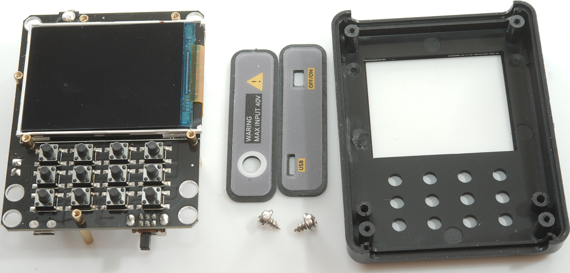
Two more screws and the circuit board was loose.
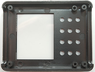
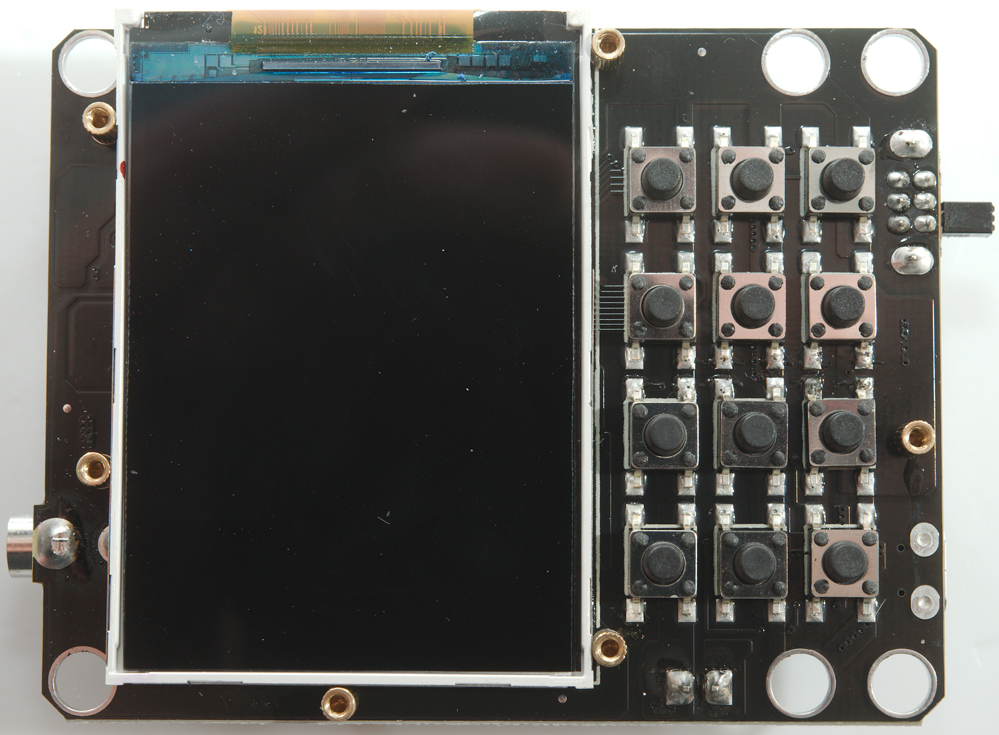
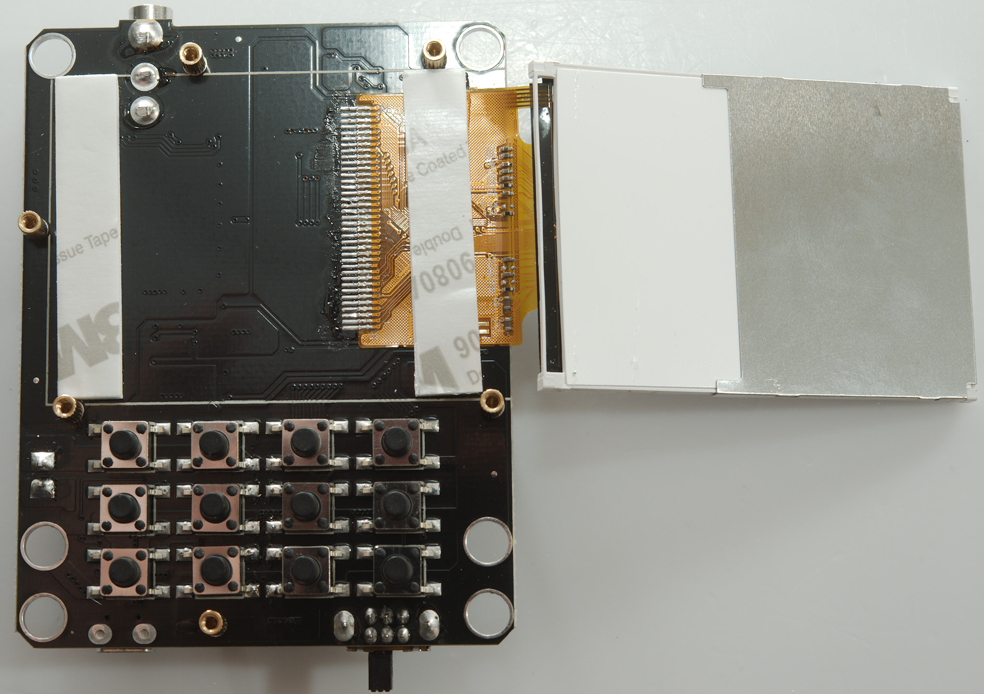
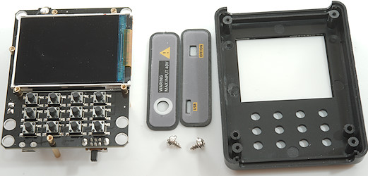
The front has holes for each button, with a membrane on the front.
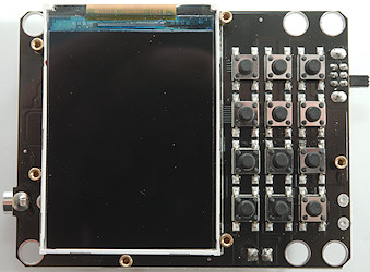
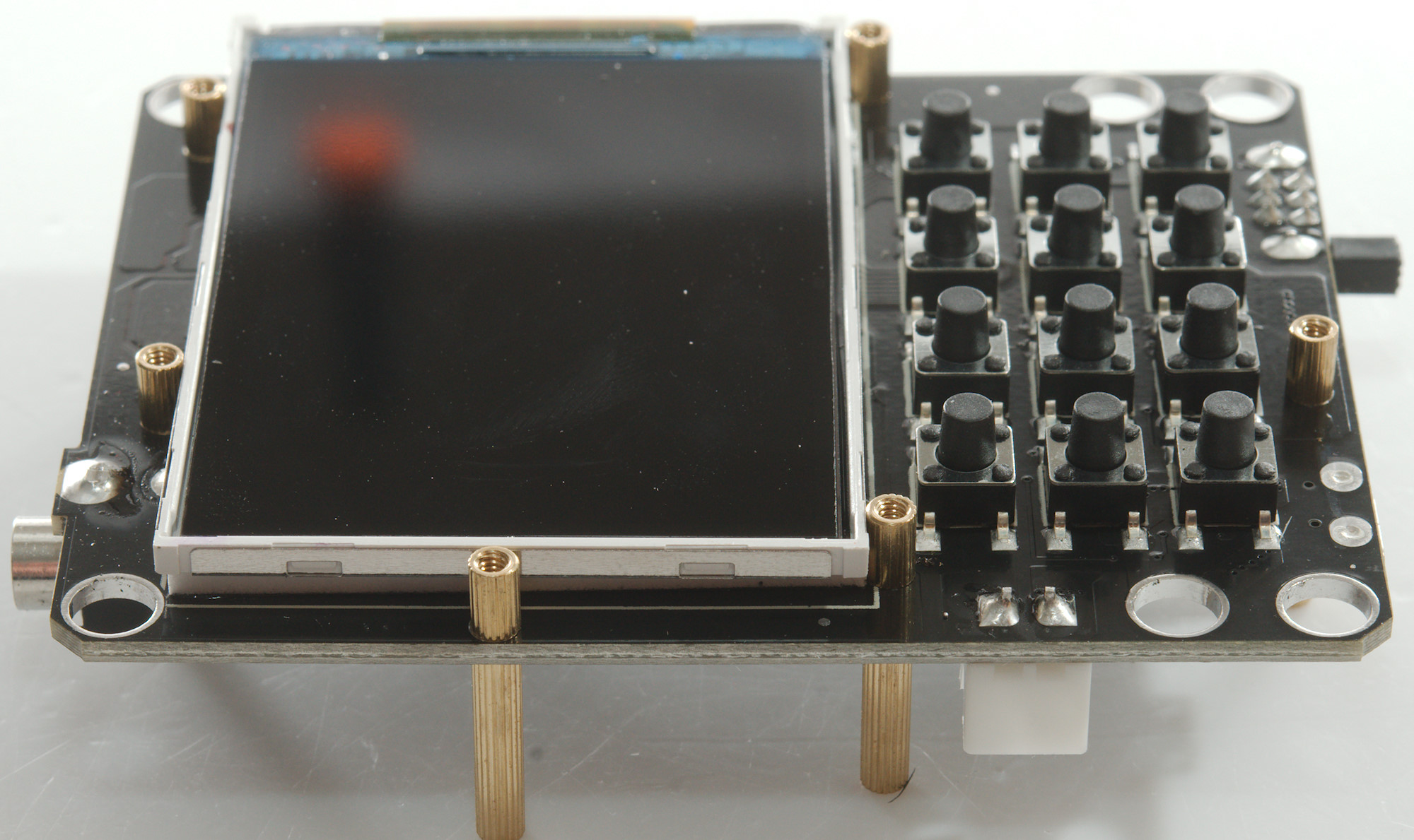
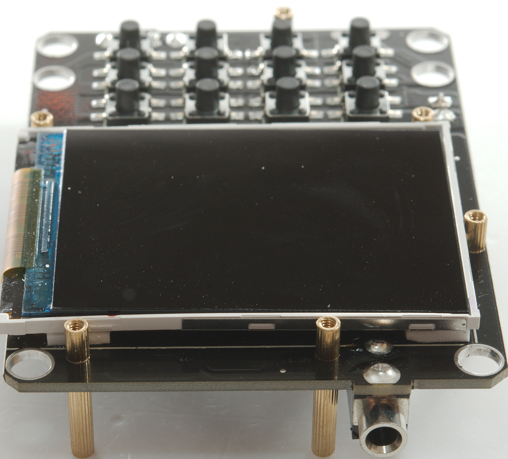
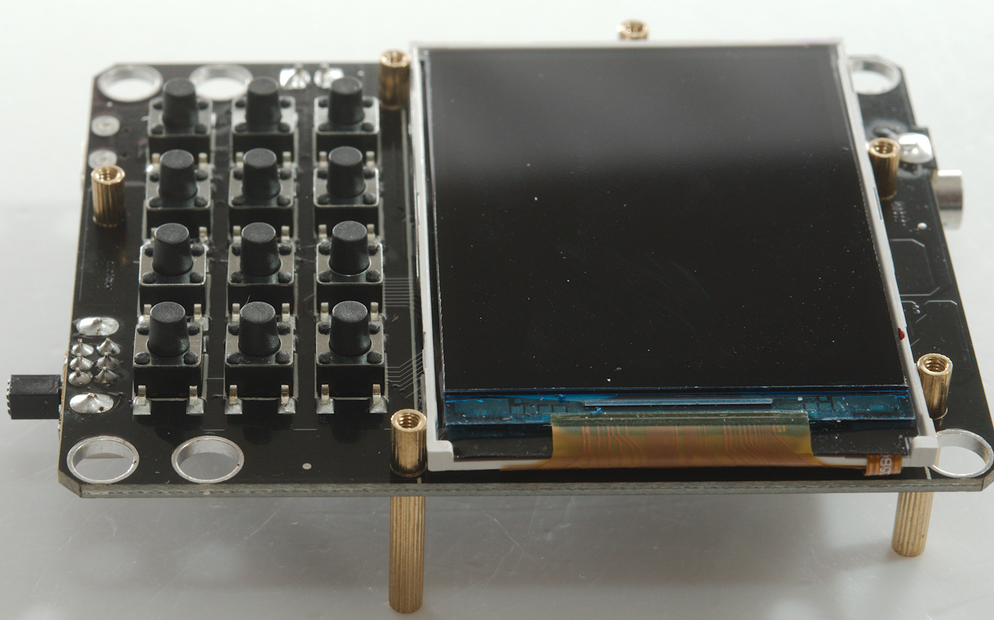
Here are all the buttons and the good looking display.
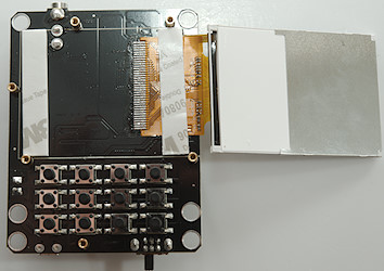
There is nothing hidden behind the display.
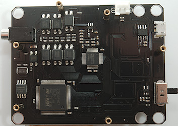
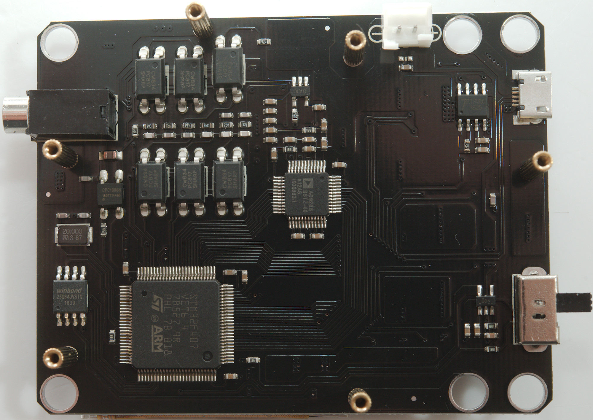
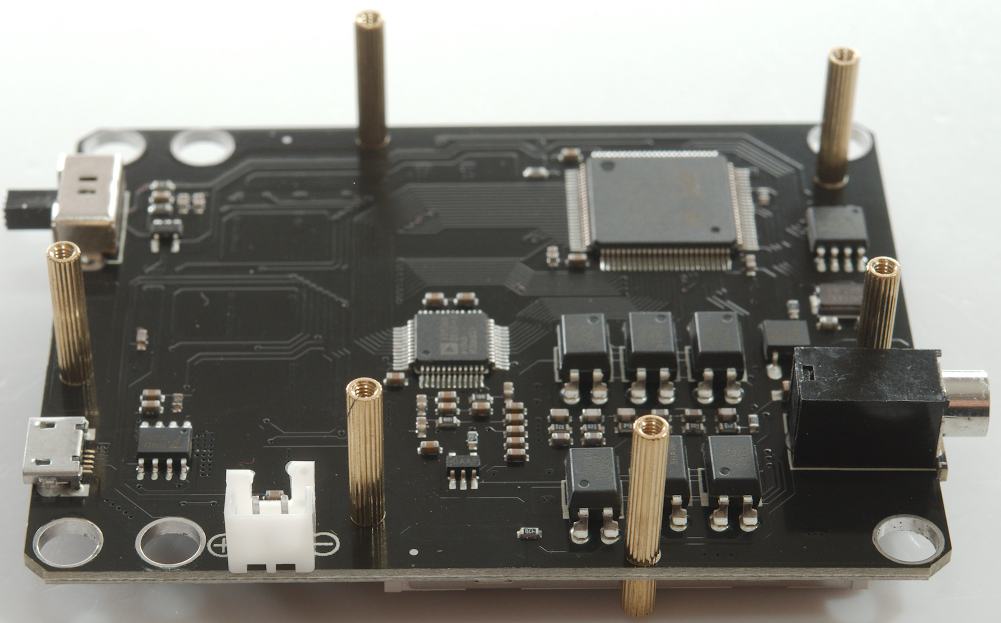
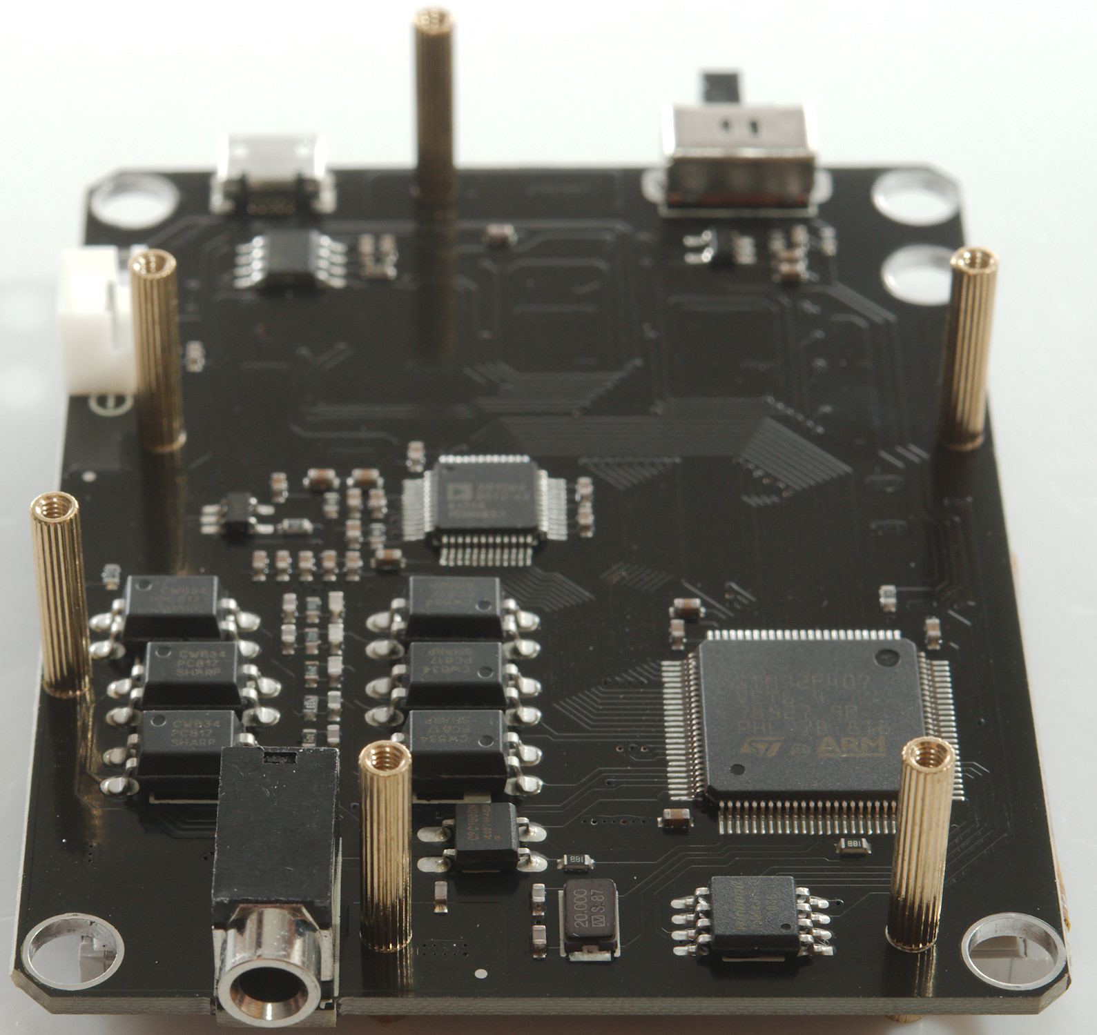
The main processor is a STM32F407VET6, this is a ARM Cortex M4. This processor has build in ADC, but for this application an external one is used (AD9288BSTZ-40 dual 8 bit 40MSPS ADC), it looks like both channels are connected to the processor. It do also have a 64Mbit memory to store waveforms in (25Q64JVSIQ)
The input range is select with a pile of optocouplers (PC817) and resistors bypassed with capacitors. For DC/AC selection is used a COC10008N opto mos relay. Between the input and the ADC is a amplifier (OPA356 marked OAAI) video OpAmp.
Behind the USB connector is a TP4056 LiIon charger and behind the switch a 3.3V regulator (TLV70033DD marked ODN).
Conclusion
With a single trigger setting this scope is much more versatile than the cheaper models, but it do have some limitations as described above. This means when working with fast stuff or want to see precise timing the scope is not ideal, but will often be usable.
I would have preferred a BNC connector on it, but it is not very hard to make my own cable with a mini jack.
The scope can help with many problems, but the specifications do not match completely.
Notes
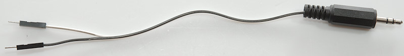
This homemade cable could be very useful, if you are using Arduino or other small micro controllers.
The oscilloscope was supplied by Banggood for review.