Small Oscilloscope DANIU DSO188
This is a very small oscilloscope with a minimum of functions.
Official specifications:
- Analog band width: 1MHz
- Maximum real time sampling rate: 5MS/s
- Vertical sensitivity: 50 mV/div-200 V/div
- Horizontal time base range: 100mS/div-2uS/div
- Maximum input voltage: 40 V (1X probe), 800 V (10X probe)
- Storage depth: 40KB
- Input resistance: 1M
- ADC precision: 12bits
- Coupling mode: AC/DC
- Trigger mode: Auto
- Trigger edge: Ascending/descending edge
- External trigger voltage 0-40V
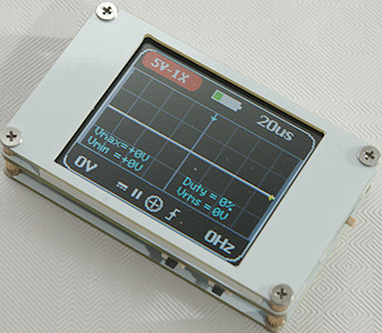
- Display: TFT color display
- Power supply: 250 mAh lithium battery
- Size: 57 x 34 x 11 mm
- Weight: 40 grams
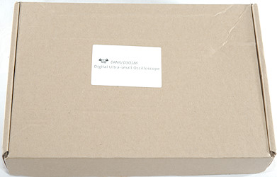
It arrives in a brown cardboard box.
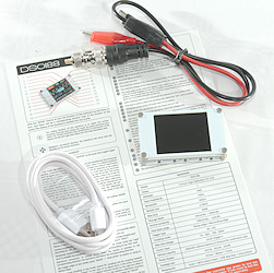
Inside is the oscilloscope, a usb cable for charging, a plug converter, a BNC to alligator clips and a instruction sheet. The instruction sheet is very simple, but explains everything on the display and how to adjust the scope. It do not in any way explain how to use a oscilloscope.
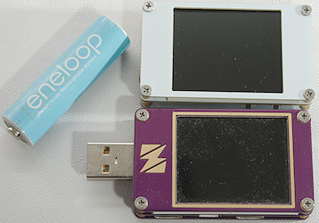
A size comparison to a large USB meter and a AA battery.
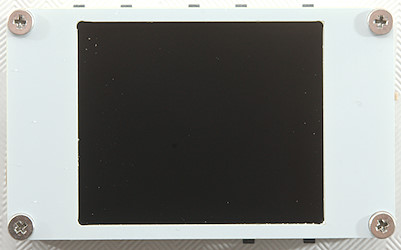
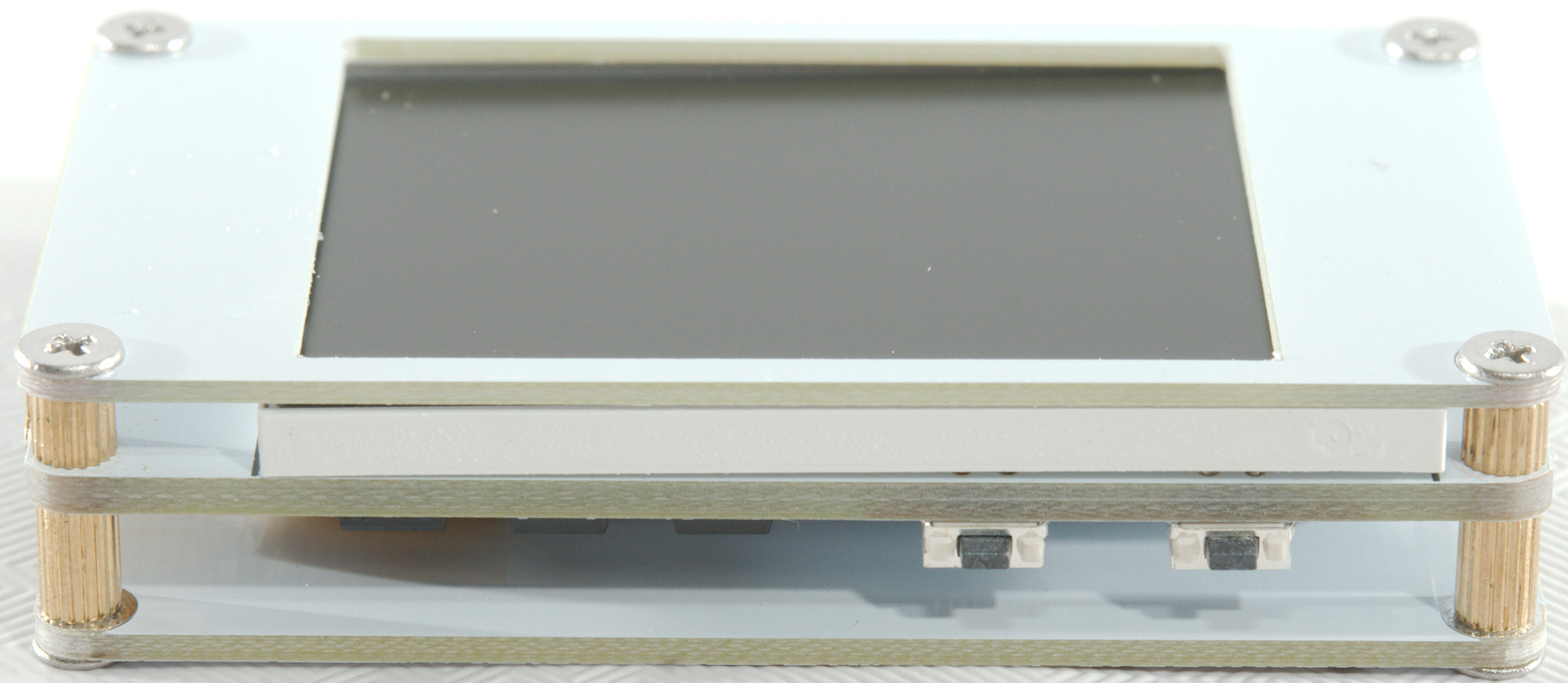
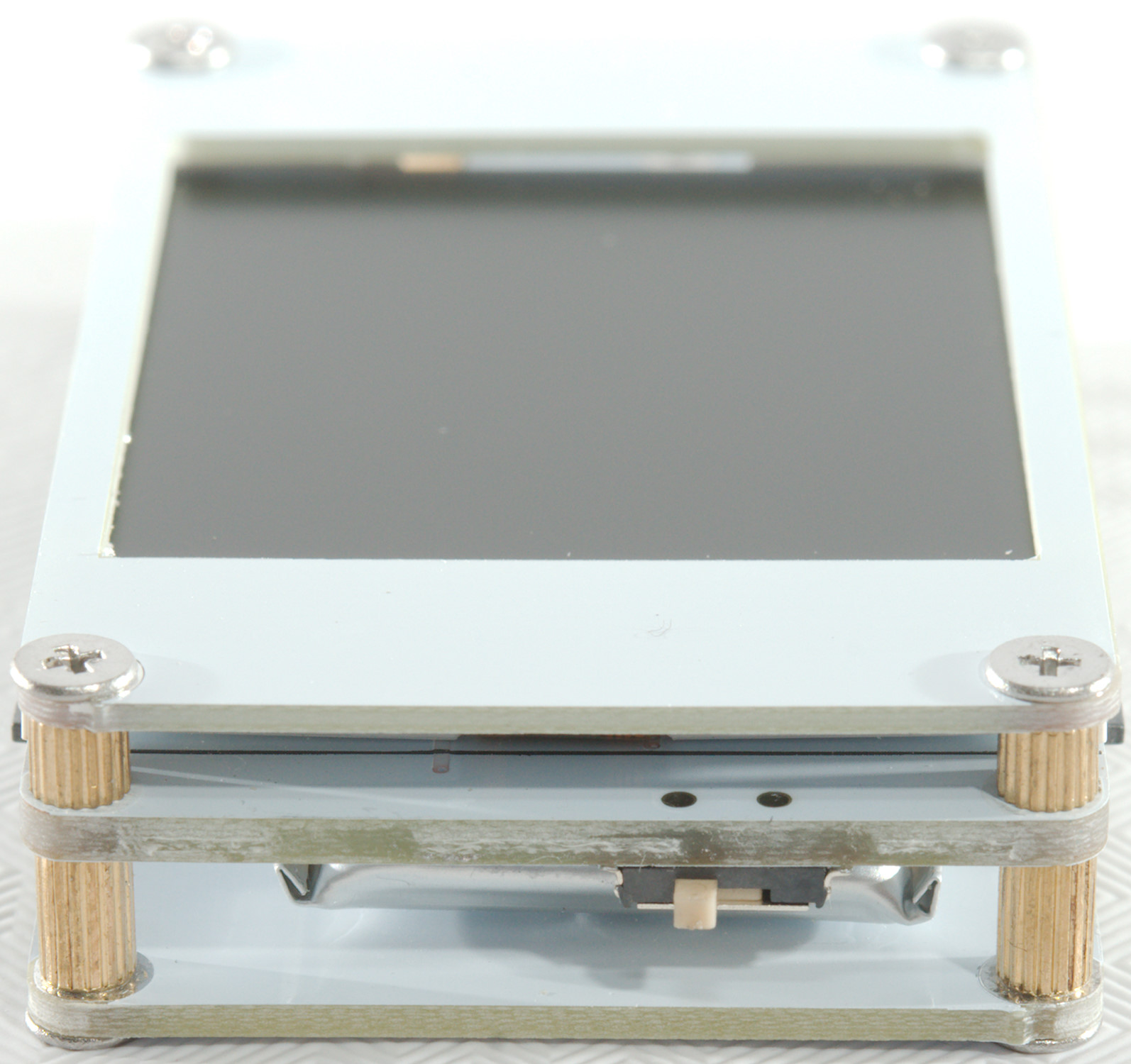
The front is only the display, nothing else.
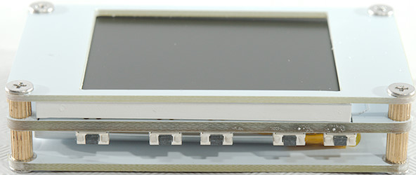
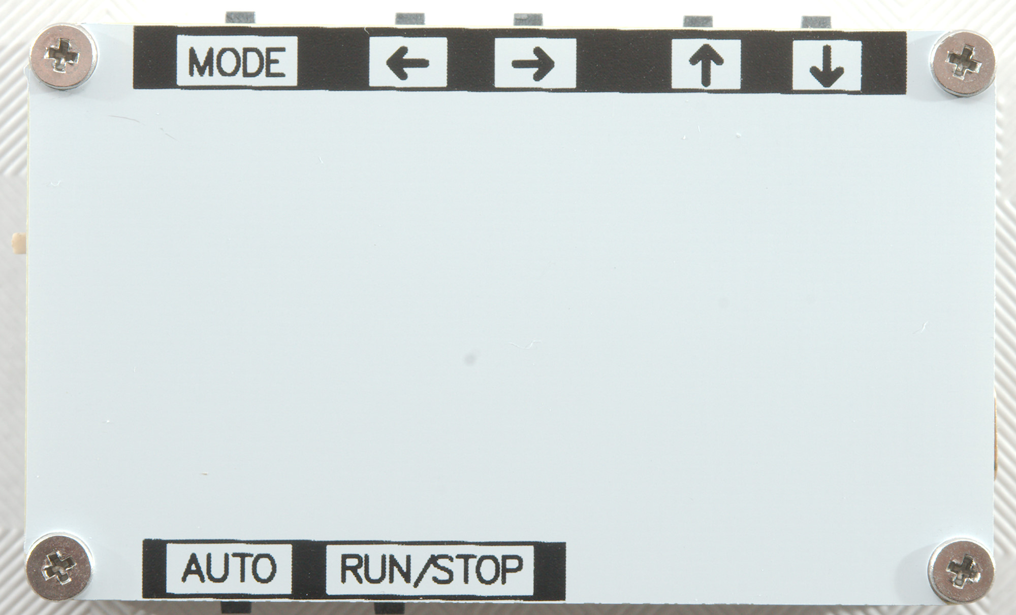
At the top is a lot of buttons, it is a MODE and two set of direction keys:
Mode 1: Adjust curve position up/down and right/left.
Mode 2: Adjust sensitivity (V/div) and trace speed (s/div).
Holding the MODE key and using on of the other keys will activate other functions: Zero calibration, AC/DC coupling, 1x/10x input, digital readout show/hide
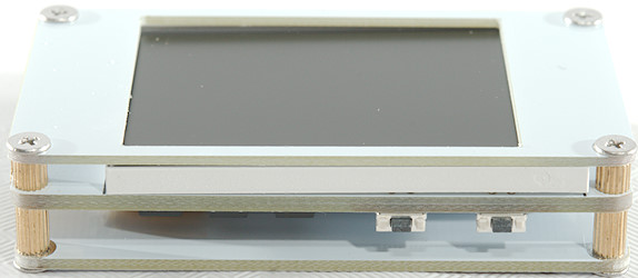
There is two buttons here, one is the RUN/STOP, it can be used to freeze the display at any time. The other is a AUTO that will try to get a decent curve on the display. The AUTO works fast with a good input signal and get a good starting position most of the time.
Holding down the MODE key and pressing RUN/STOP will switch trigger raising/falling.
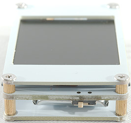
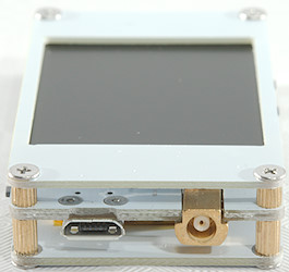
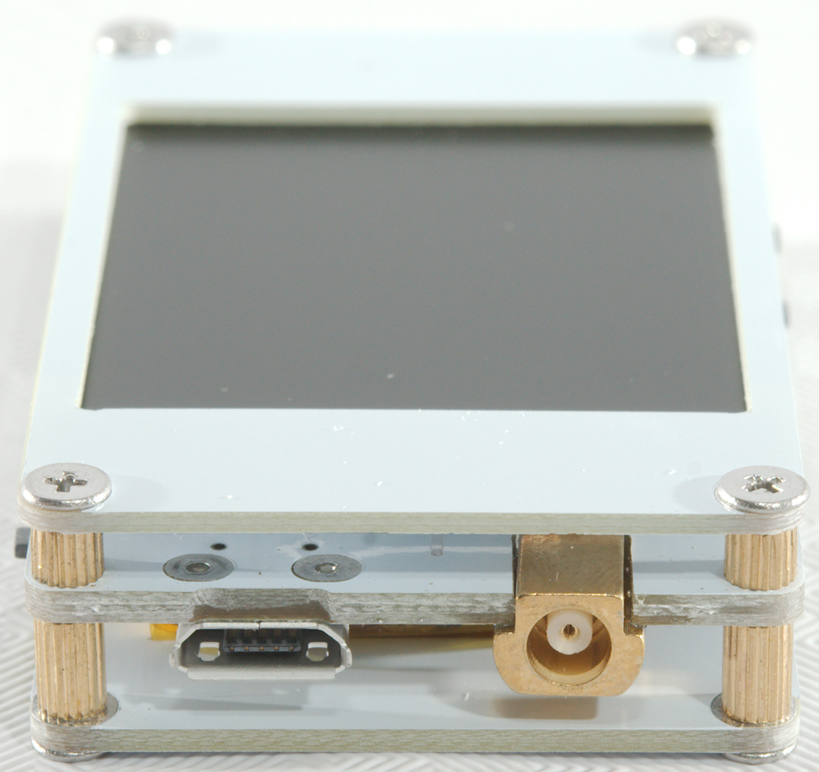
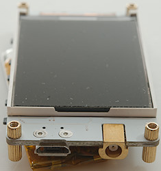
At one end is the on/off switch at the other end the input connectors. The signal input is a MCX connector, the USB connector is for charging.
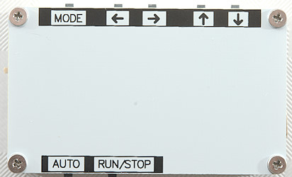
All the main key functions are listed on the bottom of the oscilloscope.
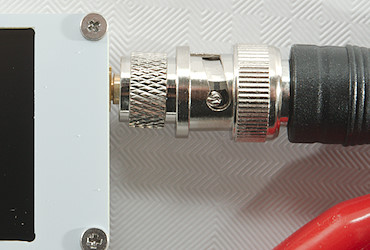
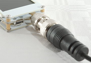
The probe connector is rather large compared to the oscilloscope.
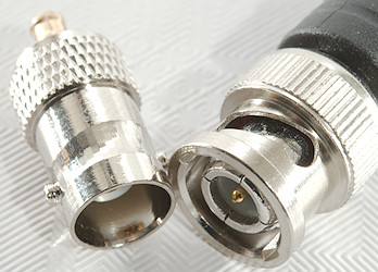
It is very nice it uses a standard BNC probe with a adapter, this means any BNC cable can be used with it, but it adds a lot to the size when you have to carry the BNC converter and cable.
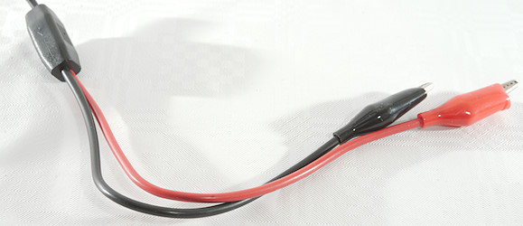
The supplied probe is alligator clips, this is fine for some applications, but usual I prefer real probes. Sadly this scope has some limits in input that prevents it from using standard 10x probes.
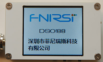
When powered on it shows a brand name and model number and some text I cannot read.
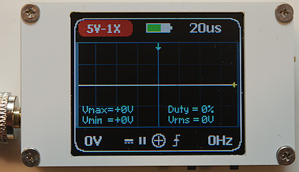
Then it changes to the oscilloscope view, it do not remember last settings and always starts like this.
Testing
A oscilloscope is not a multimeter, i.e. do not expect precise voltage measurements, this is also valid for more expensive scopes (But they are more precise than this).
- Time/div settings: 2us, 5.5us, 10us, 20us, 50us, 100us, 200us, 500us, 1ms, 2ms, 5ms, 10ms, 20ms, 50ms, 100ms
- Volt/div settings (1x): 50mV, 0.1V, 0.2V, 0.5V, 1V, 2V, 5V, 10V, 20V
- Volt/div settings (10x): 50V, 100V, 200V (Why no overlap with the lower voltages, this would be useful)
- Input impedance: 510kOhm for both AC & DC (This means it will not work with standard probes)
- AC coupling can show small AC voltage on large DC voltages, it adds a capacitor in series with the input.
- Input capacitance: 134pF (138pF in the 3 lowest voltage ranges). 10x do not change it.
- Current draw from battery when off: less than 0.01uA
- Current draw from battery when on: 106mA
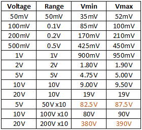
First a voltage check with a DC supply. It is not very precise, but except for the 50V and 200V settings (I did not use a 10x probe, this means it must show 10 times the voltage I apply) it gives a good idea about the voltage.
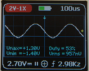
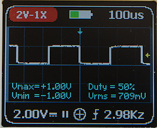
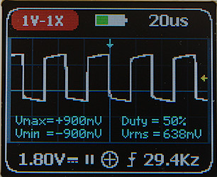
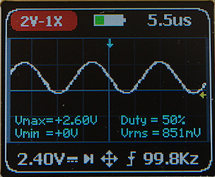
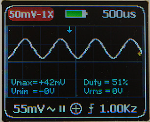
Lets start with a 3kHz 1Vrms sinus (+/-1.41V), when switching to square wave it is still 1Vrms (+/-1.0V).
The duty cycle on the sine wave is not precise, it is on the square wave, but the square wave has trouble with calculating Vrms.
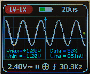
Lets increase the frequency with the same voltages. At 30kHz the input is attenuated more, but the waveforms are perfectly usable, same with the duty cycle measurement.
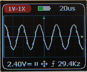
To get a larger display of the curve, I disabled the readout.
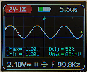
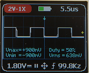
100kHz works fine.
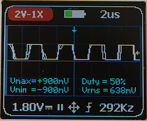
At 300kHz the curves looks a messy (It is always it is made of 3 curves on top of each other). The 2us/div is also the maximum sweep speed.
What about a DC offset, here I moved the curve just above the zero line. The line at top of the display is not the real curve. Pressing AUTO fixes the display.
The yellow arrow at the right border is the zero voltage. This also shows Vrms is calculated for the AC part (Like a multimeter does).
20mVrms on top of 9VDC, this works fine with AC coupling and can be used to measure ripple on a power supply.
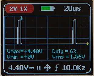
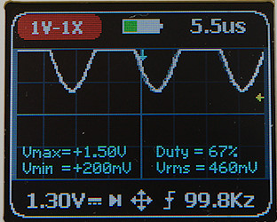
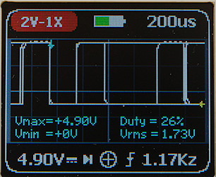
Checking a 10kHz 5% PWM, this curve shows it nicely.
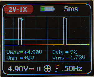
Servo pulses on a Arduino.
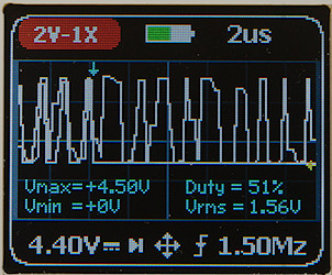
Two situations where it is not working, the first is neopixel data the second is a serial communication. The 3 data sets on top of each other makes it really messy to look at, it is also missing a adjustable trigger to capture this.
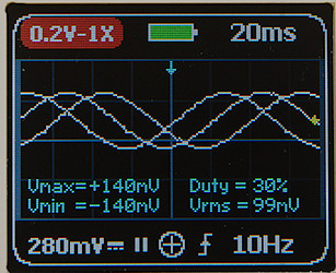
The display shows 3 curves at a time, usual on top of each other, but at 10Hz and 100mVrms the trigger did not work correctly, increasing frequency or voltage was enough to fix it.
When freezing the display (Using RUN/STOP) one of the curves can be moved left/right, but not up/down.
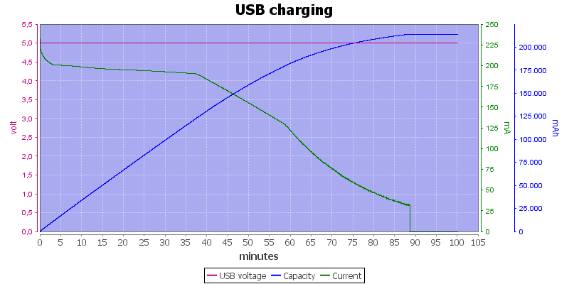
I also wanted to see how fast it charges the battery. From empty to full it takes about 1½ hour. It is only charged with slightly above 200mAh, this may be because it shuts down before the battery is empty (Because it needs above 3.3V) or because the battery has less capacity than stated. It will give close to two hours runtime.
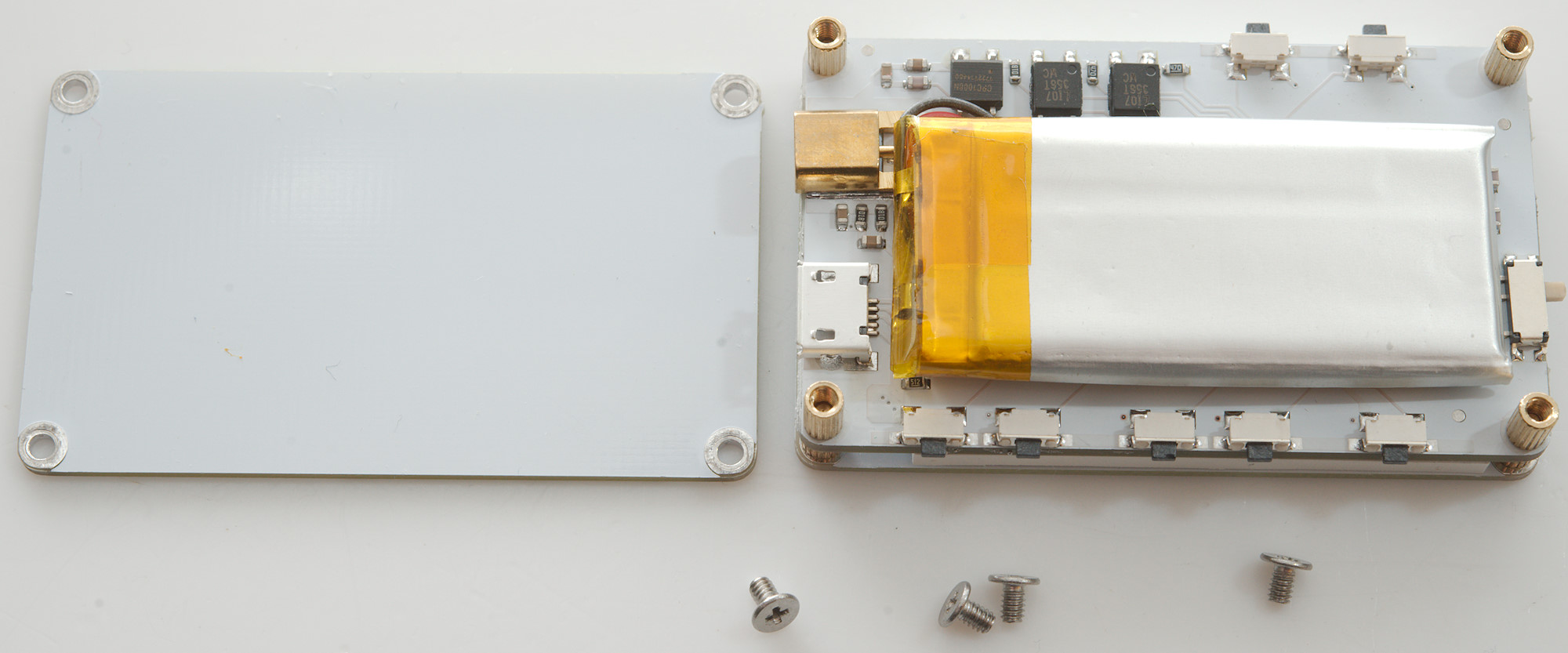
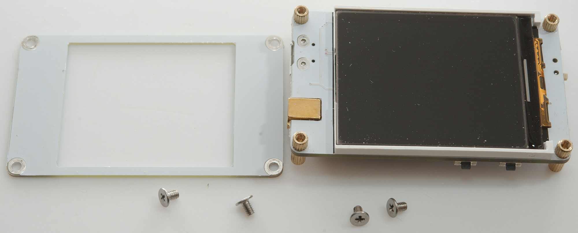
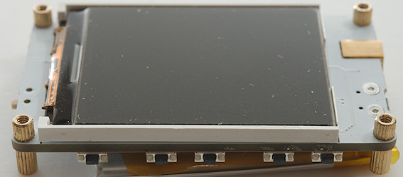
Tear-down
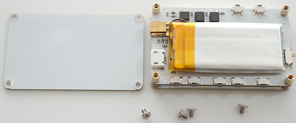
It is easy to open: four screws on the back
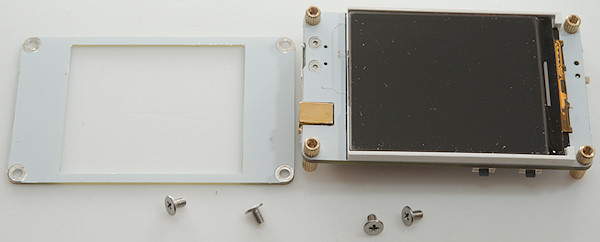
And four screws on the front.
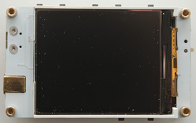
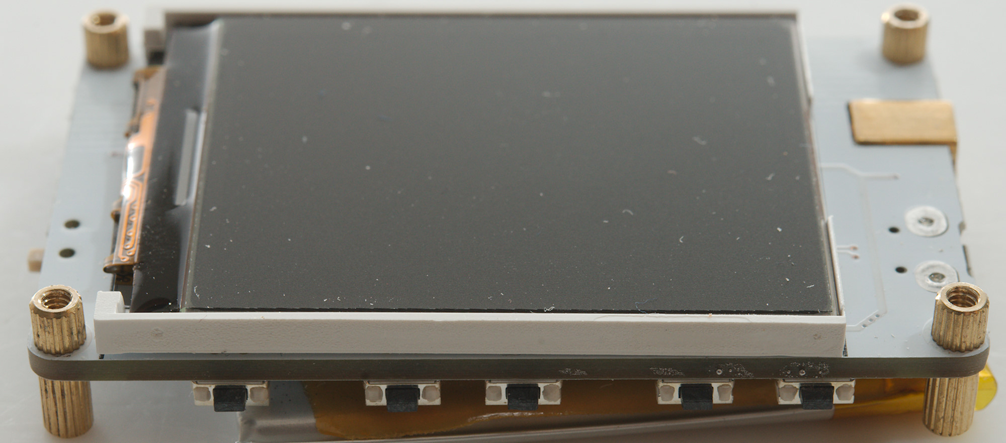
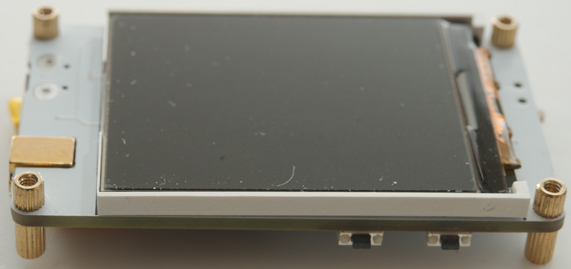
The front is only the display. It is glued to the circuit board and I did not remove it.
On one end is the connection to the display, one the other the input connectors.
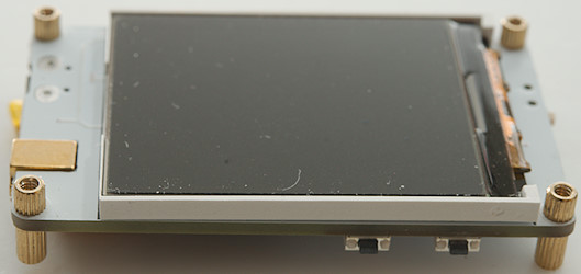
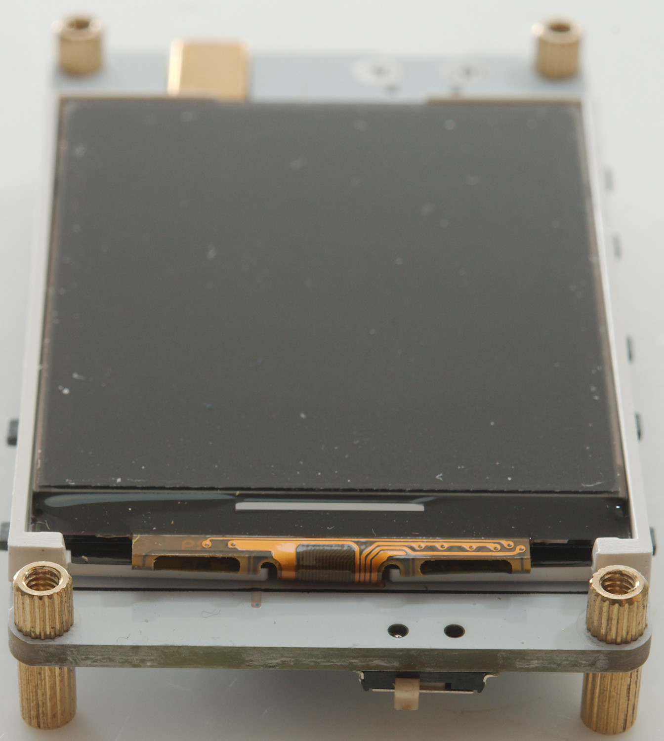
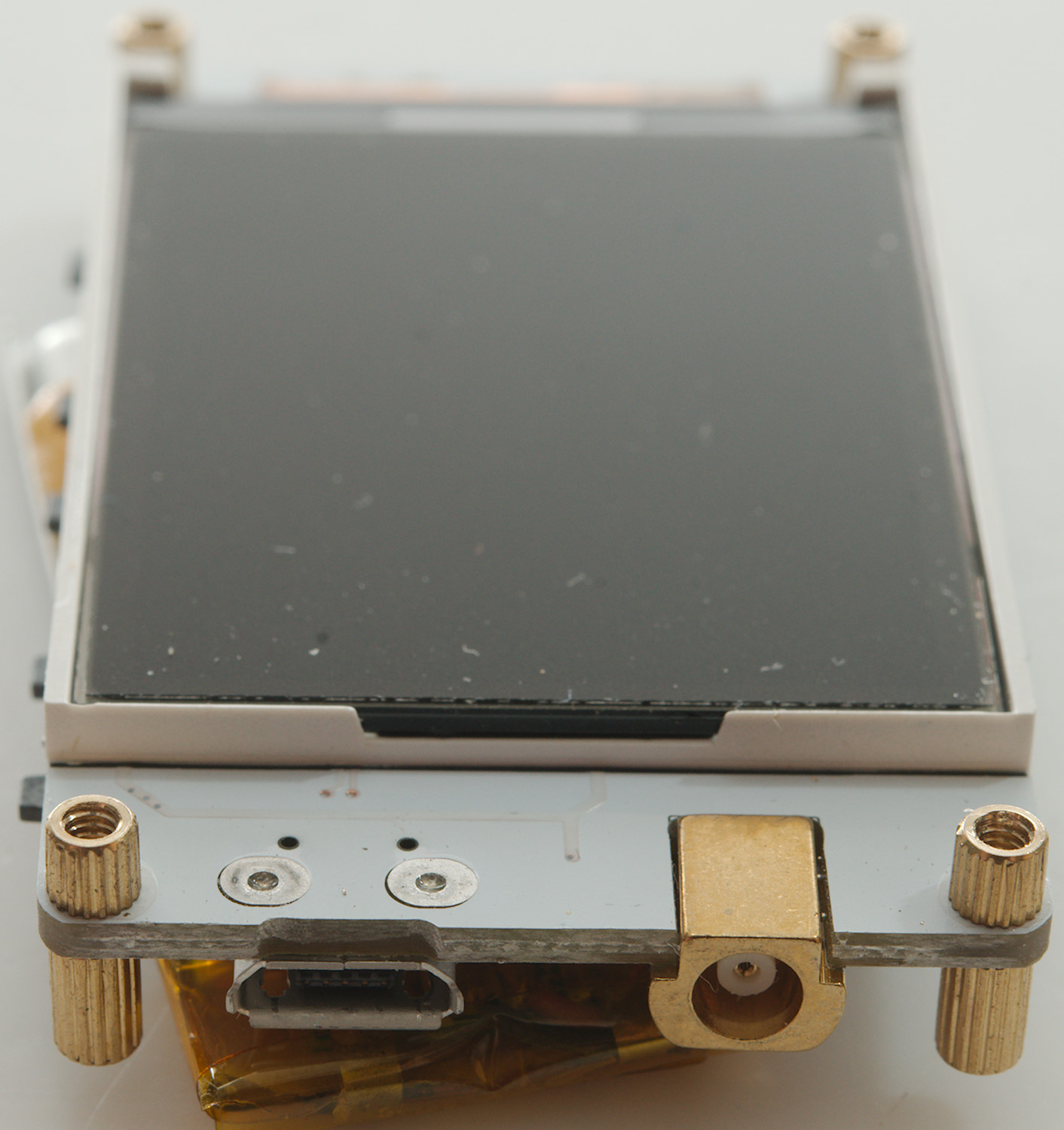
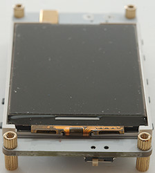
Not much to see from the sides.

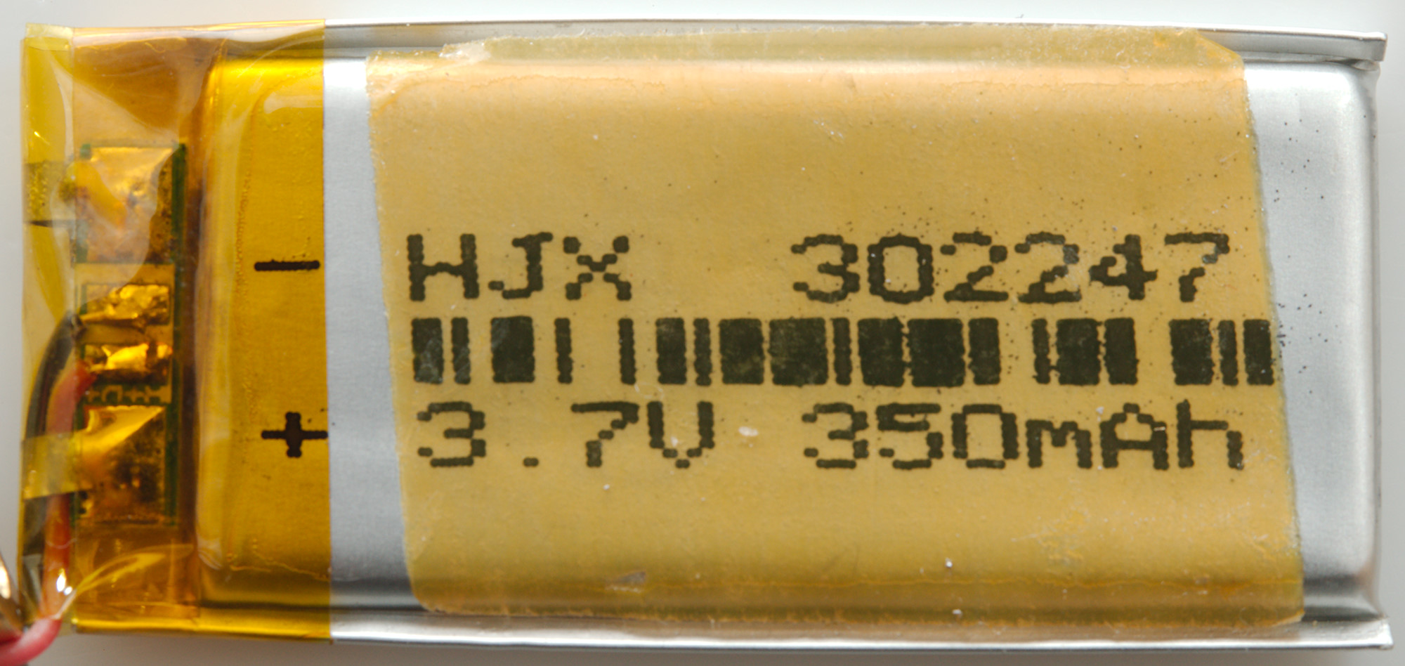
The battery is not the rated 250mAh, but a 350mAh type and it looks like it has protection build in.

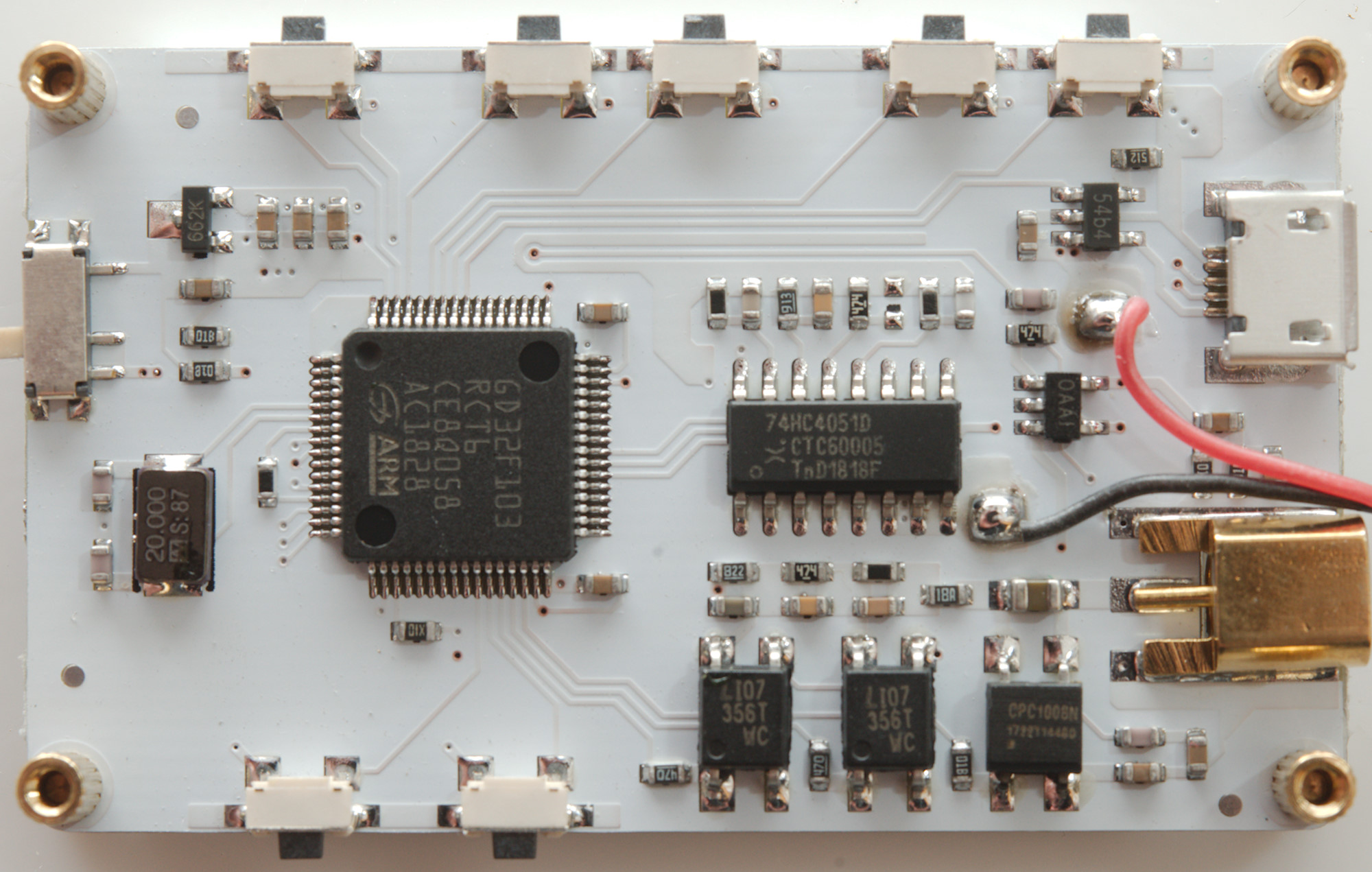
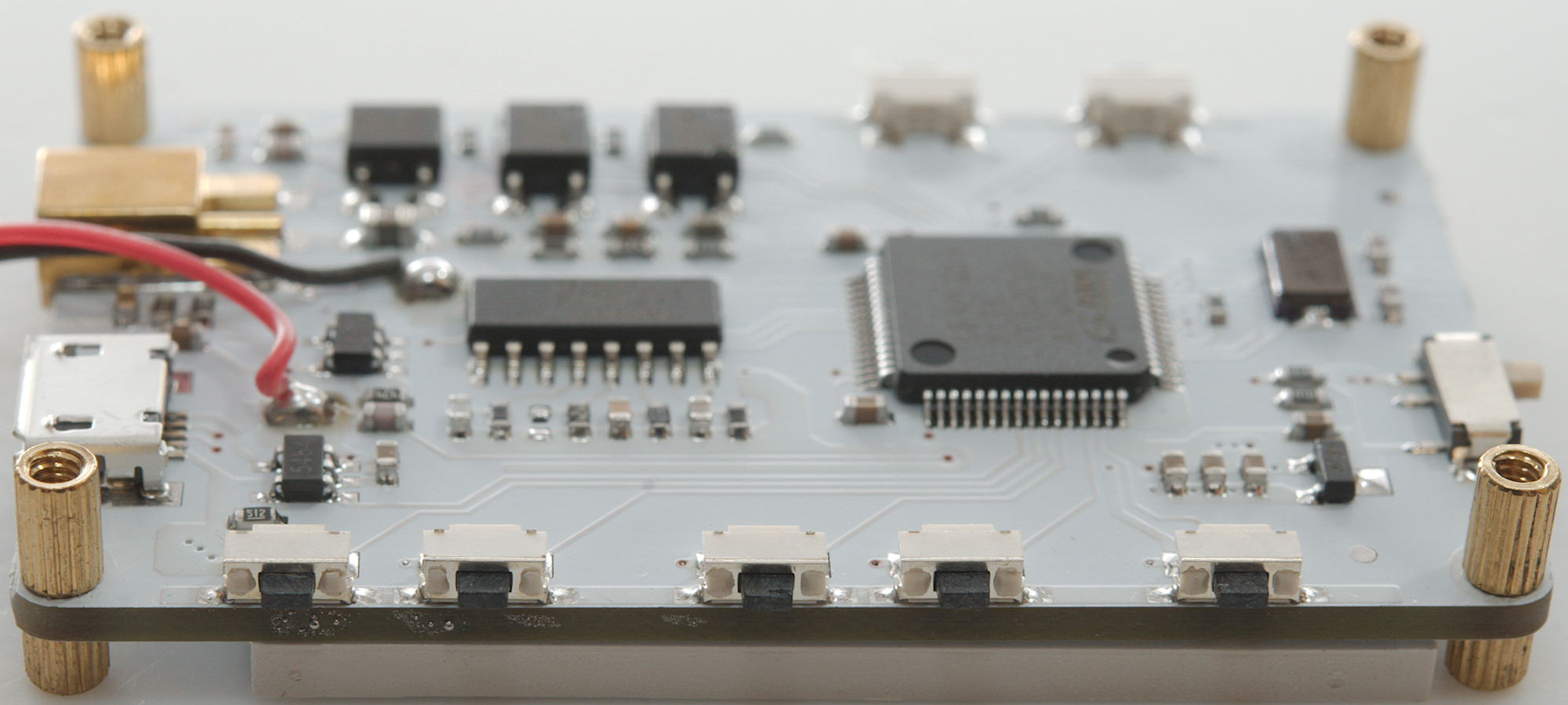
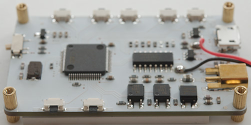
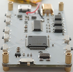
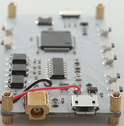
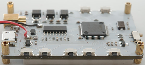
Lets start with the small chip near the on/off switch (662K: XC6206P332MR 3.3V 200mA LDO regulator), it is the voltage regulator. The large chip (GD32F103RCT6: ARM Cortex M3: 108MHz 256K Flash 48K SRAM) is the microprocessor that does everything. The ADC is 12bit with up to 1 MSPS, but it does not have a preamplifier.
On the other side of the processor is a analog multiplexer (74HC4051: 8 to 1), this must be for most of the range selection. Below it are two opto-couplers (LTV-356T) and a opto mos relay (CPC1006N) for the AC/DC selection.
There is also a OpAmp (OAAI: OPA356AIDBV 200MHz GB) to handle the low ranges. I could not find data on the chip near the USB connector, but I would expect a LiIon charge chip.
Conclusion
It is a very small oscilloscope and it has some useful functionality, it can show repetitively curves, this could be PWM or a boost/buck regulator curves or ripple (Use a series resistor to check current), but it cannot capture single events, this is stuff like serial communication.
Generally I like it, but it really is missing a possibility to manually adjust the trigger in addition to the automatic trigger. Ability to use standard probes would also have been nice.
It is never going to compete against a fully featured scope, but for a simple very small curve checked it works fine and has a fairly good bandwidth.
Notes
The oscilloscope was supplied by Banggood for review.