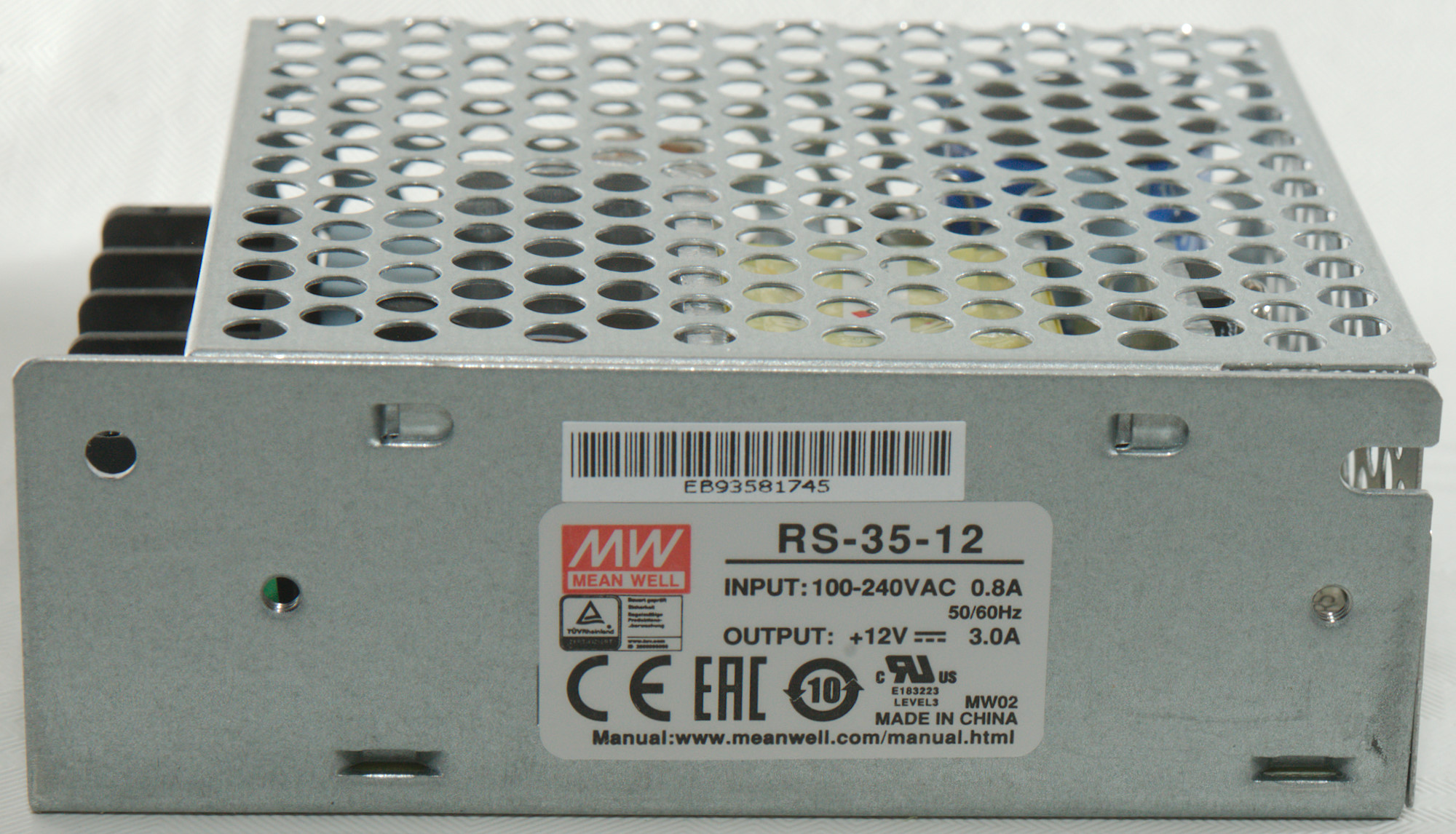
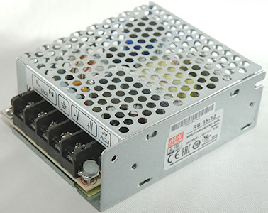
AC-DC 12V 3A MeanWell RS-35-12 Switching Power supply
Official specifications:
- DC voltage: 12V
- Rated current: 3A
- Current range: 0-3A
- Rated power: 36A
- Ripple & noise: 120mVpp
- Voltage adjustment range: 10.8V ~ 13.2V
- Voltage tolerance (includes line & load regulation): 1.0%
- Input voltage range: 88V ~ 264V
- Frequency range: 47Hz ~ 63Hz
- Efficiency (Typ.): 81%
- AC current (Typ.): 0.55A/230VAC
- Inrush current (Typ.): 36A/230VAC
- Leakage current: <2mA/240VAC
- MTBF: 249khrs min. (This means there is about 70% probability that the unit will work 10 years)
- Dimension: 99 x 82 x 36mm
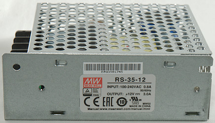
I got it from elfadistrelec.dk, this means it is a original MeanWell
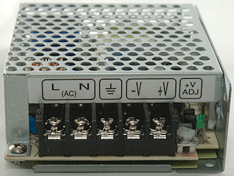
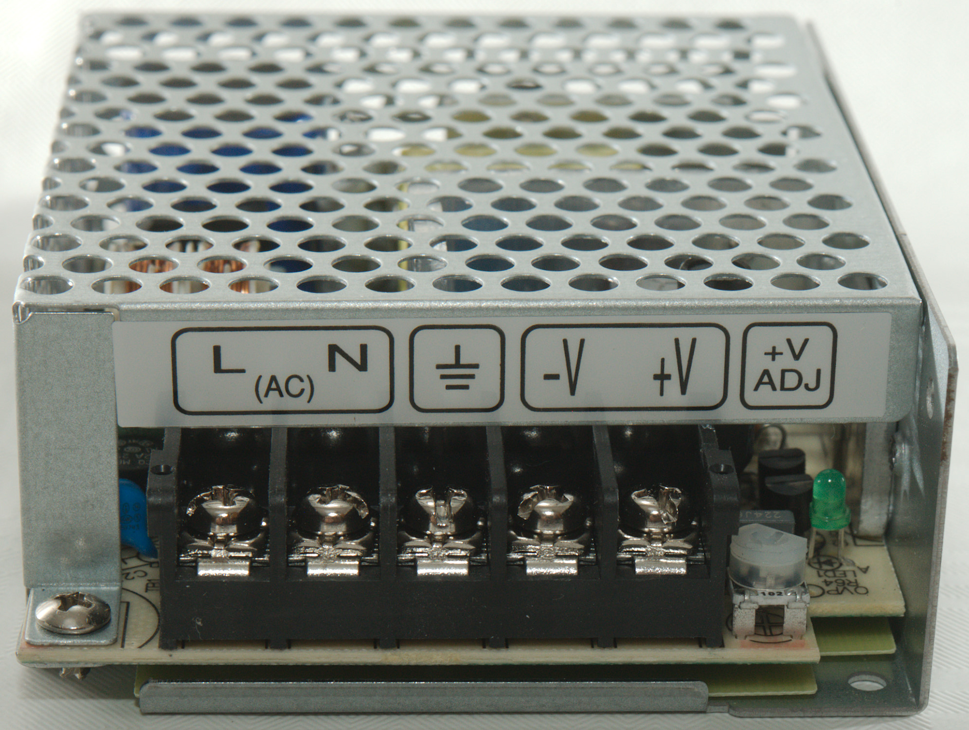
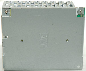
The front is fairly standard with AC input, eartch, DC output, voltage adjustment and a green led (Partially hidden) to show that power is on.
Measurements
- Default output voltage: 12.06
- Minimum output voltage: 10.10
- Maximum output voltage: 13.54
- Power consumption when idle is 0.25 Watt.
- Weight: 278g
- Size: 99 x 82 x 35mm
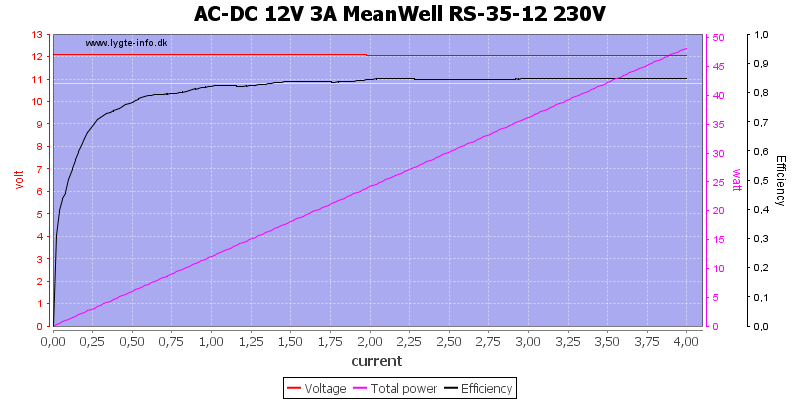
The power supply can deliver 4A before the overload protection kick in.
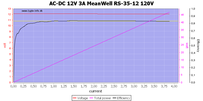
At 120VAC it can deliver 3.9A, still well above the rated 3A
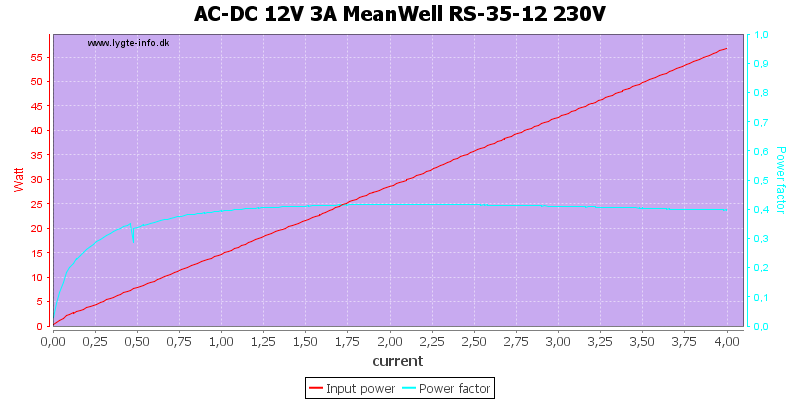
As usual with small power supplies the power factor is rather low.
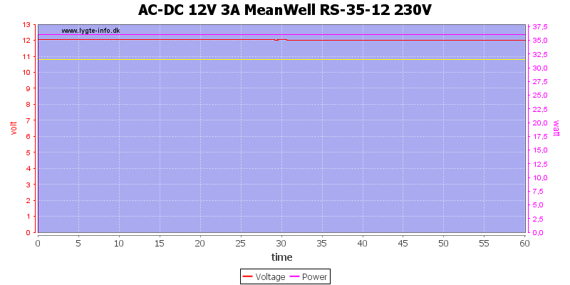
There was no problem running at 3A for 1 hour.
The temperature photos below are taken between 30 minutes and 60 minutes into the one hour test.
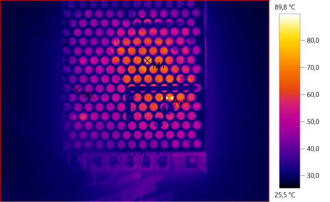
M1: 73.1°C, M2: 44.3°C, HS1: 89.8°C
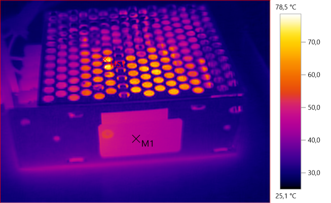
M1: 46.4°C, HS1: 78.5°C
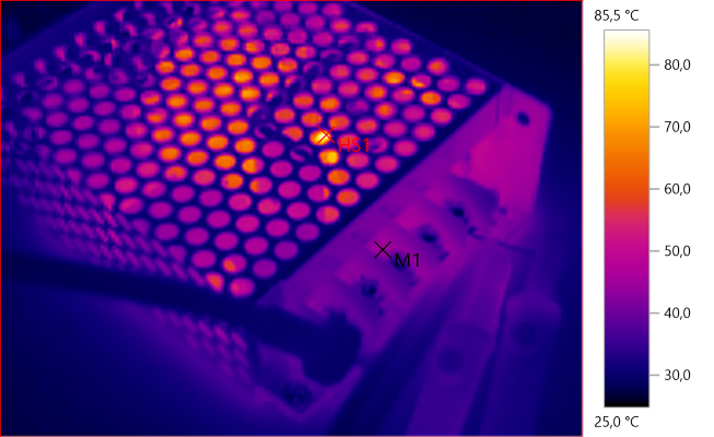
M1: 44.4°C, HS1: 85.5°C
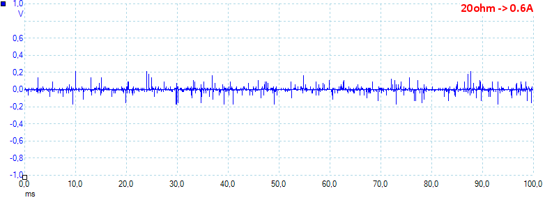
At 0.6A load the noise is 17mV rms and 459mVpp.
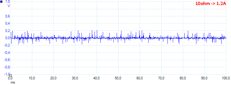
At 1.2A load the noise is 18mV rms and 560mVpp.
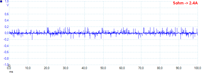
At 2.4A load the noise is 21mV rms and 454mVpp.
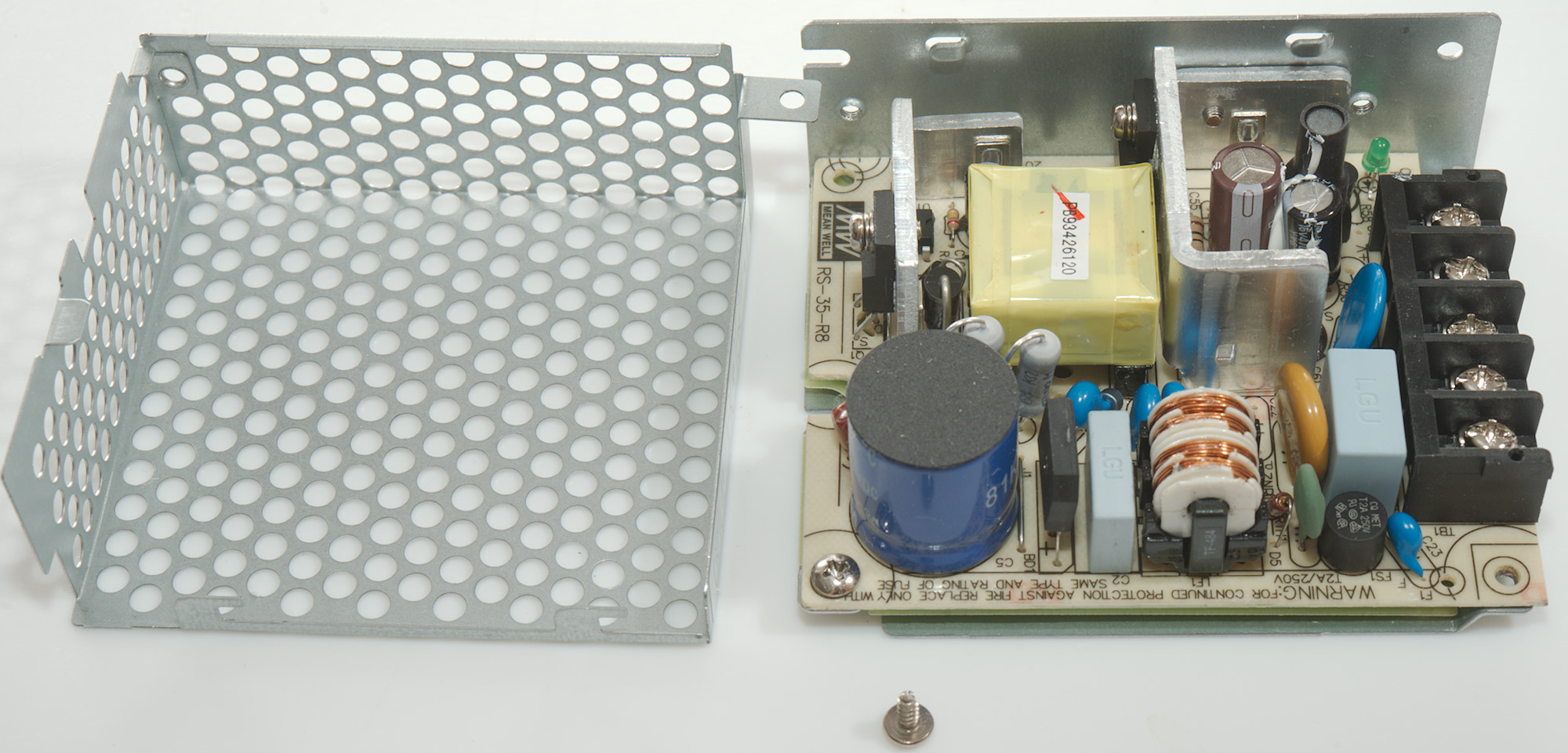
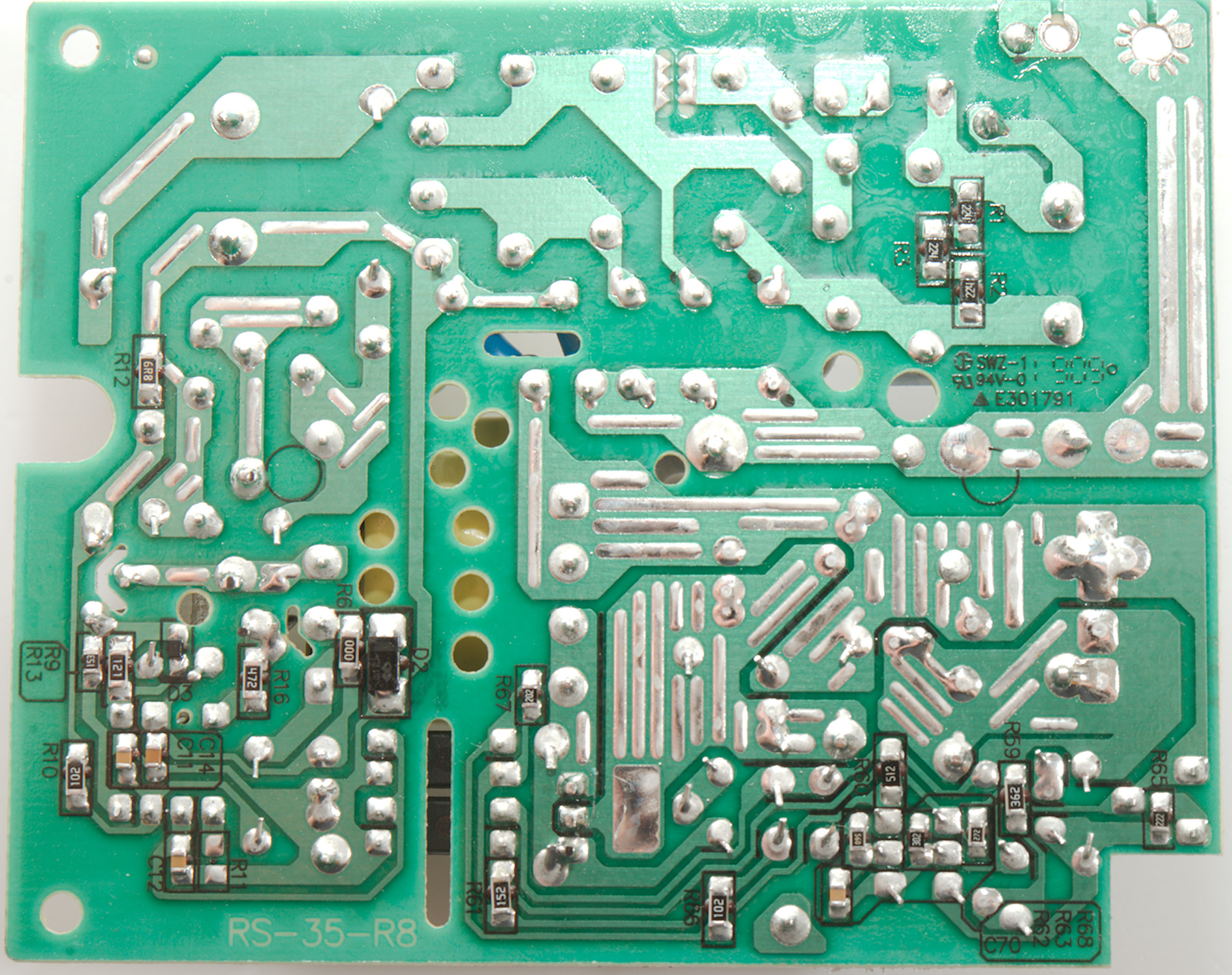
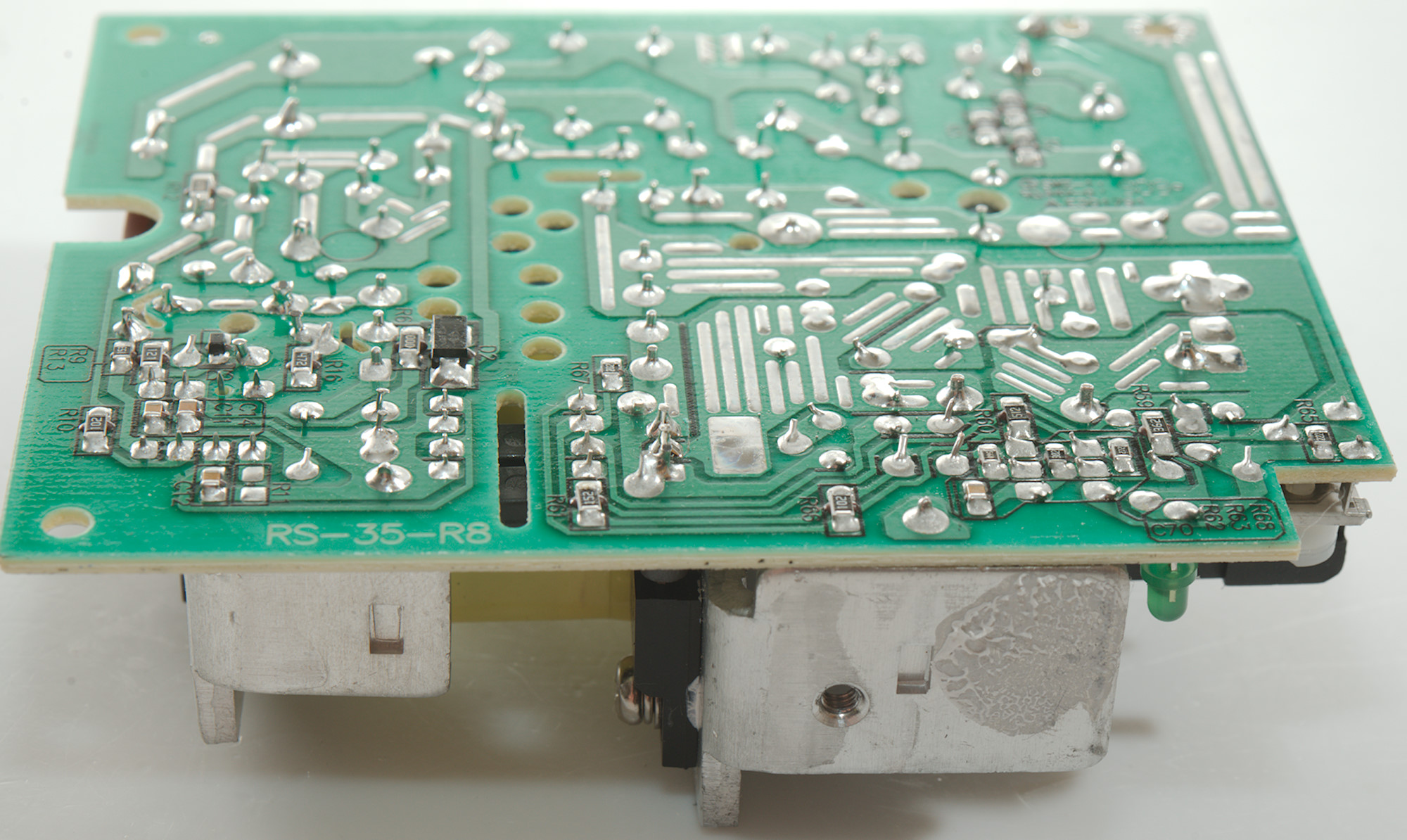
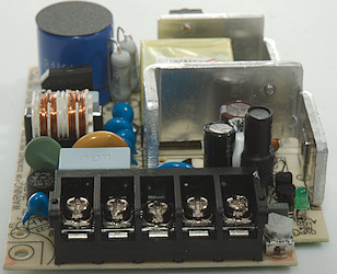
Tear-down
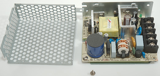
I only had to remove one screw to open the frame.

There was two more screws before I could remove the circuit board, one was holding the rectifier heatsink to the frame.
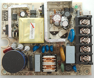
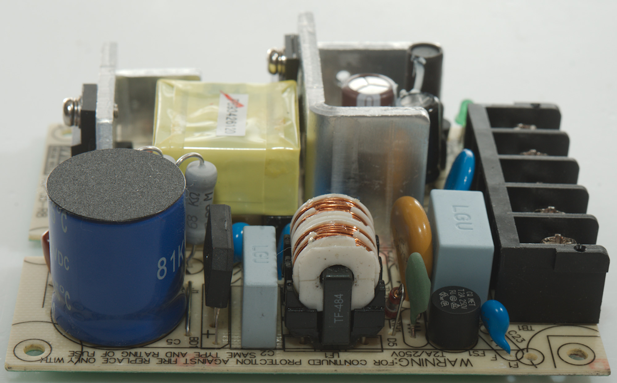
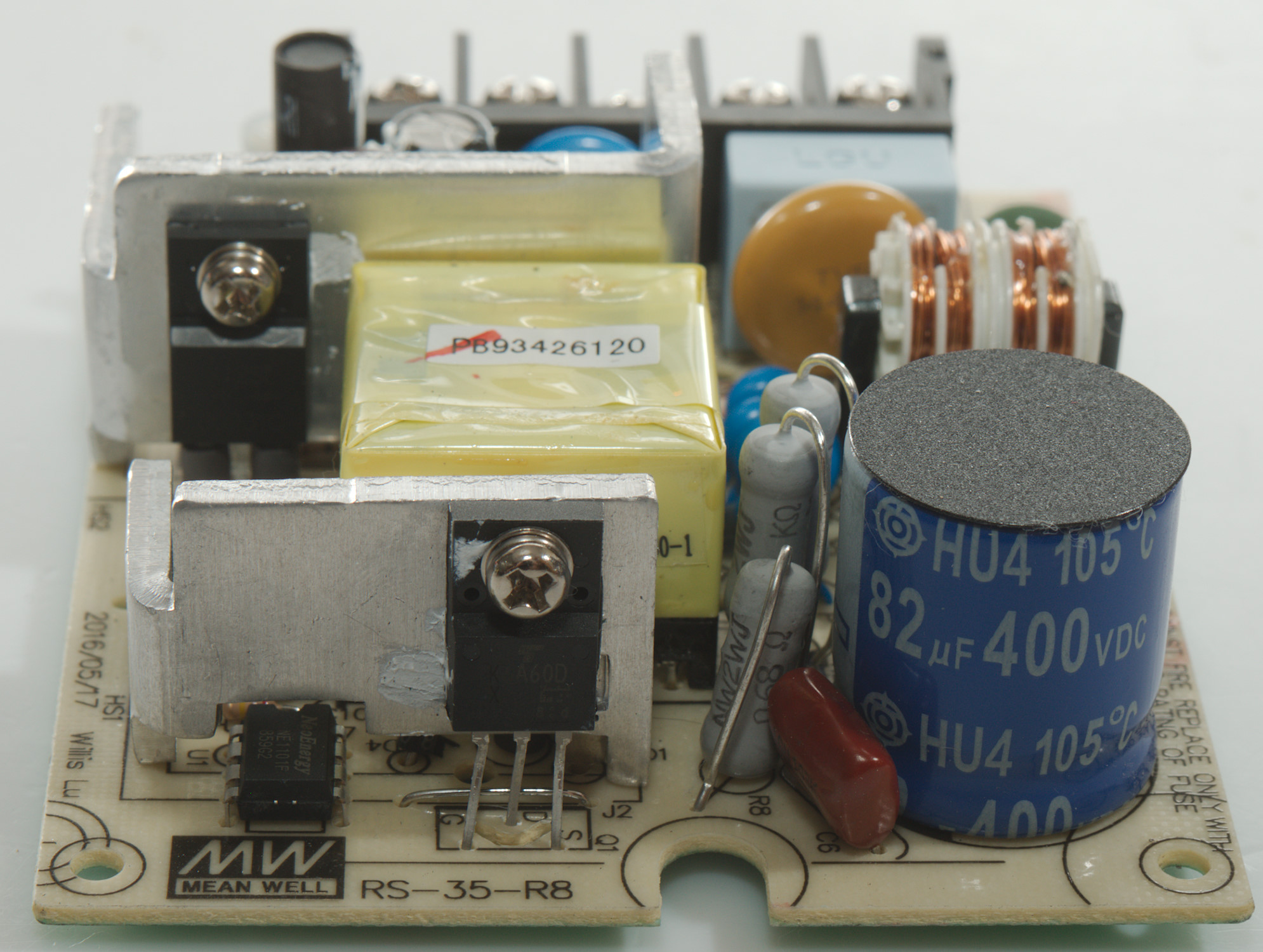
At the input is the usually fuse (FS1), a PTC (green) and a MOV (ZN: 470V), followed by a common mode coil (LF1) and a row of safety capacitors (C3, C4, C30, C31). This means a fairly high leak current. Next in line is the bridge rectifier (BD1) and the smoothing capacitor. There is two power resistors (R4, R5: 2x68kohm) in parallel as part of the snubber network. There is also a series resistors (R8: 0.68ohm) to measure switching current.
The main switcher transistor is mounted on a heatsink with the switcher controller chip (U1: NE1101) below. There is two optocouplers (U2 & U3) for feedback.
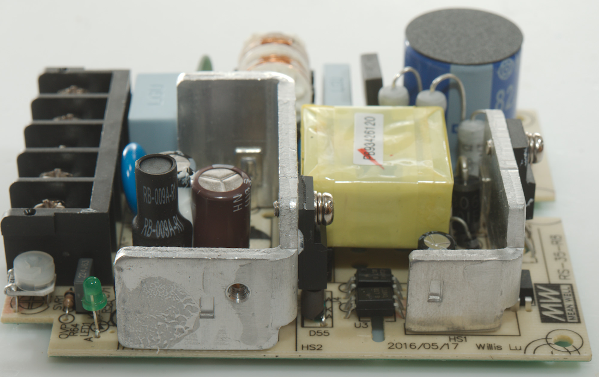
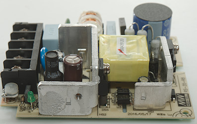
The low volt side has a large rectifier diode (D55) on a heatsink. The two smoothing capacitors (C56 & C60) has a inductor (L51) between them. There is a capacitor from the output to the earth terminal, it is not a safety capacitor, but a 2kV type.

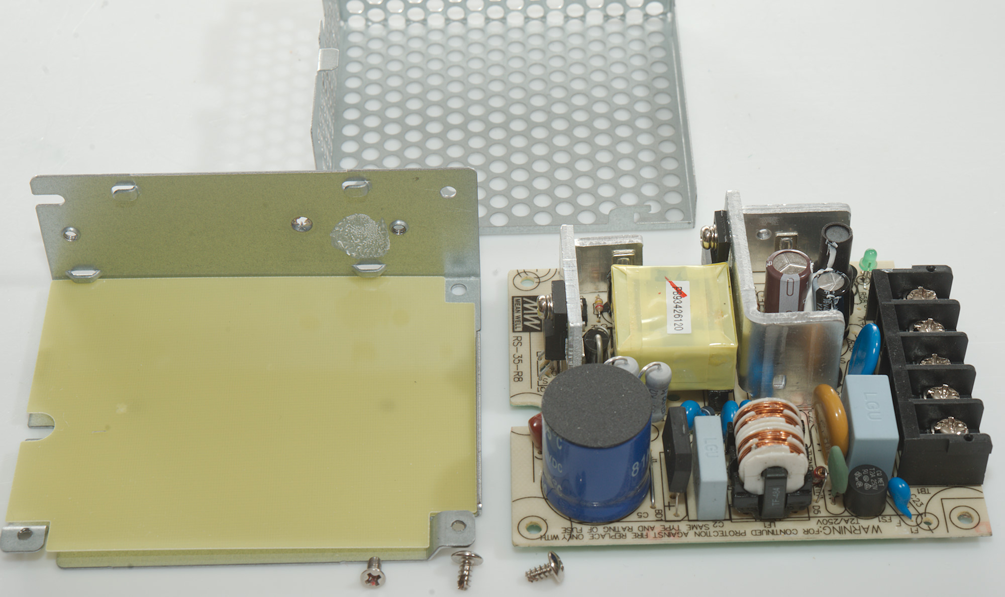
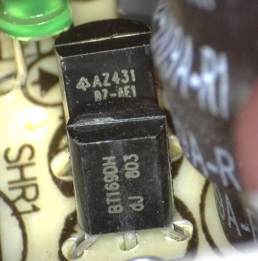
The reference is a AZ431 and there is a SCR, probably to shut down the output in case of overvoltage.
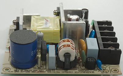
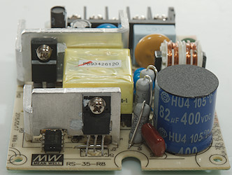
The input smoothing capacitor has insulation on top, because it is close to the frame.
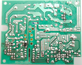
One this side of the circuit board is a couple of resistors, capacitors and a single diode.

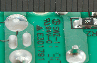
Between mains and earth there is nearly 6mm.
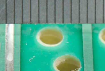
There is well above 6mm between mains and low volt side.
Testing with 2830 volt and 4242 volt between mains and low volt side and frame, did not show any problems, but the leakage current from mains to low volt side is about 0.4mA (Rating says below 2mA, equipment without earth must not leak more than 0.25mA).
Conclusion
A industrial supply that is designed to use earth connection, it works fine and can deliver the rated power.
Notes
Read more about how I test (USB) power supplies/charger
How does a usb charger/small power supply work?