230VAC-DC 5V 2A Switching Power supply
Official specifications:
- Input voltage: AC 100V-240V 50-60Hz
- Output voltage: 5V
- Output current: 2A
- Size: 7.2*3.4*2.5cm
- Overvoltage Protection: Yes
- Overcurrent protection: Yes
- Short circuit protection: Yes
I got it from ebay dealer bestbuy_ca
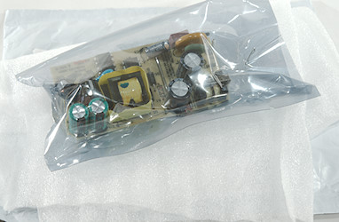
This charger arrived in a envelope without any accessories.
It looks like it has been removed from a product with the cut wires.
Measurements
- Power consumption when idle is 0.16 watt
- Weight: 44g
- Size: 73 x 36 x 24mm
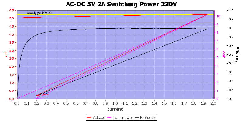
This power supply module is list as a 2A module, but that looks slightly optimistic, it can deliver 1.9A.
It has cable compensation (I had a 4 terminal connection at the end of the short remaining wires), this compensation may match the cable it was supposed to be used with.
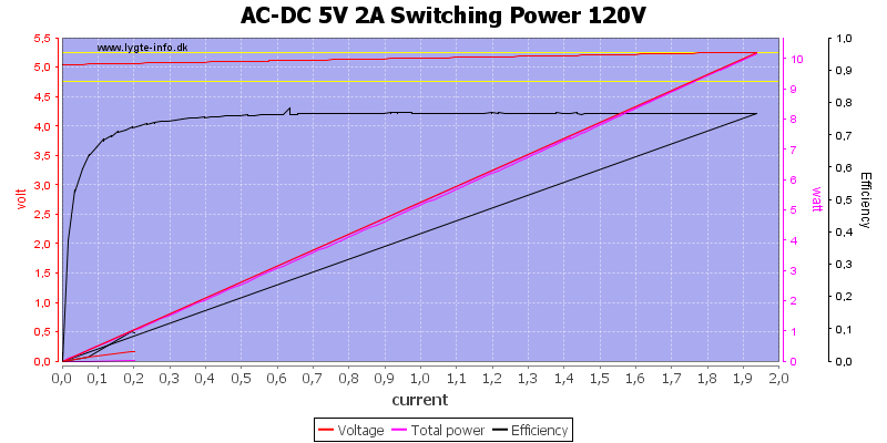
At 120VAC performance is the same, except efficiency goes slightly down.
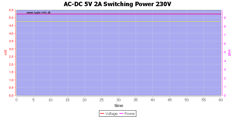
There was no problem running at 1.8A for 1 hour.
The temperature photos below are taken between 30 minutes and 60 minutes into the one hour test.
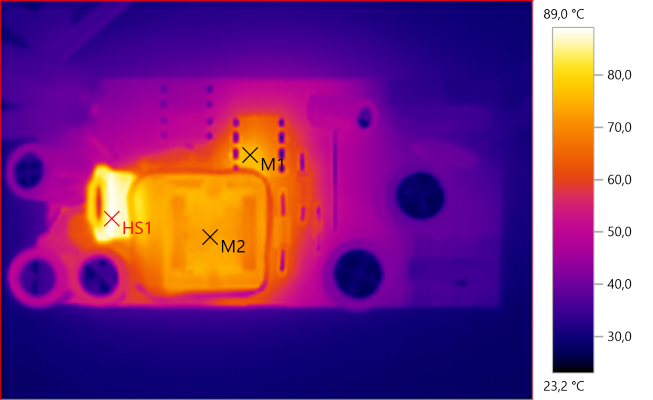
M1: 76.2°C, M2: 73.0°C, HS1: 89.0°C
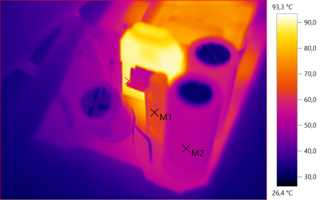
M1: 63.1°C, M2: 52.1°C, HS1: 93.3°C
The hottest part is the rectifier diode, the switcher IC and the transformer is also heated, but not as much.
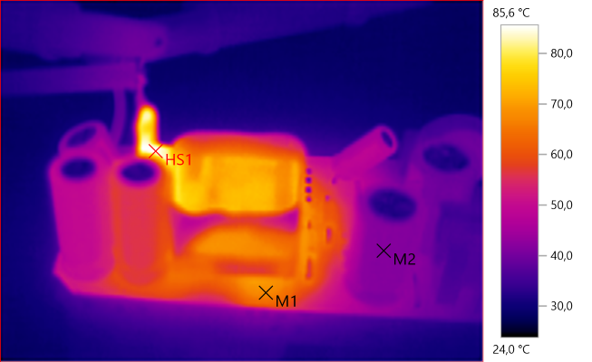
M1: 67.6°C, M2: 41.7°C, HS1: 85.6°C
The rectifier diode is probably rated for 150°C inside and here it is close to 100°C, this looks acceptable.
The centre of the diode is metal and do not register on the IR camera.
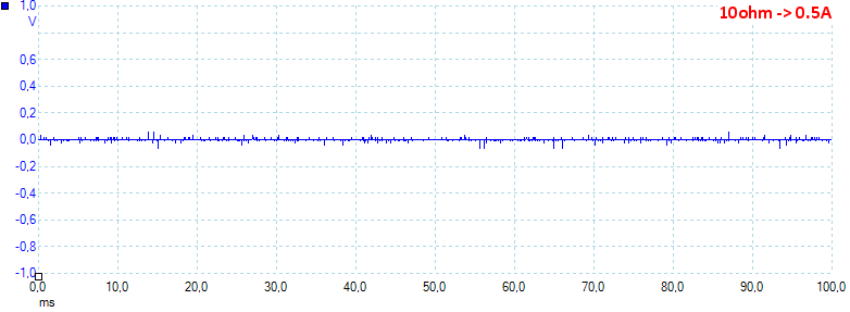
At 0.5A the noise is 5mV rms and 168mVpp.
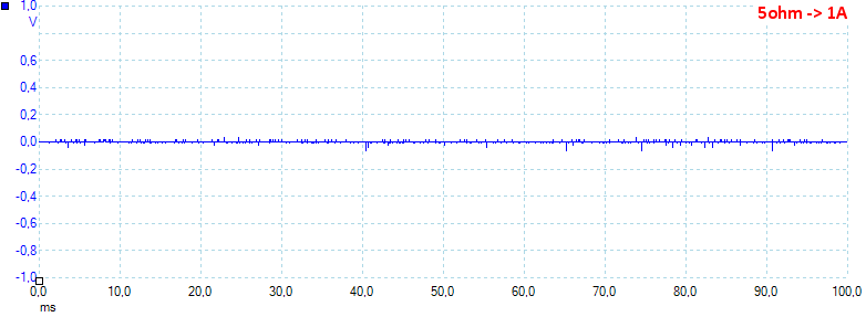
At 1A the noise is 5mV rms and 172mVpp.
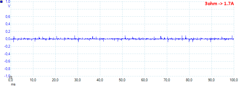
At 1.7A the noise is 9mV rms and 163mVpp, all very low values.
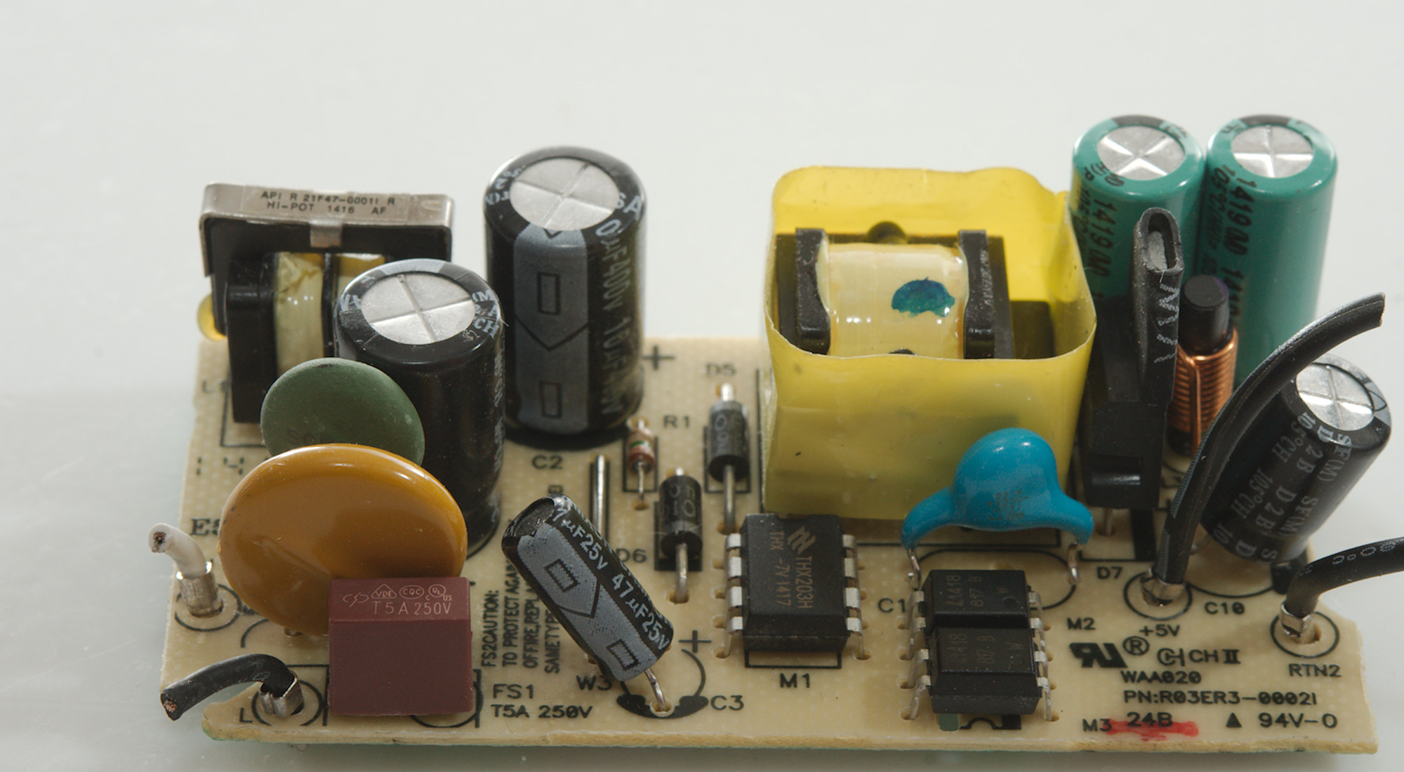
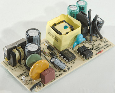
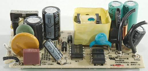
A look at the electronic
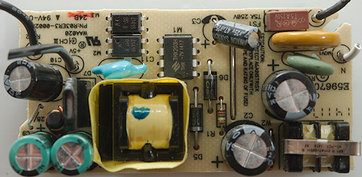
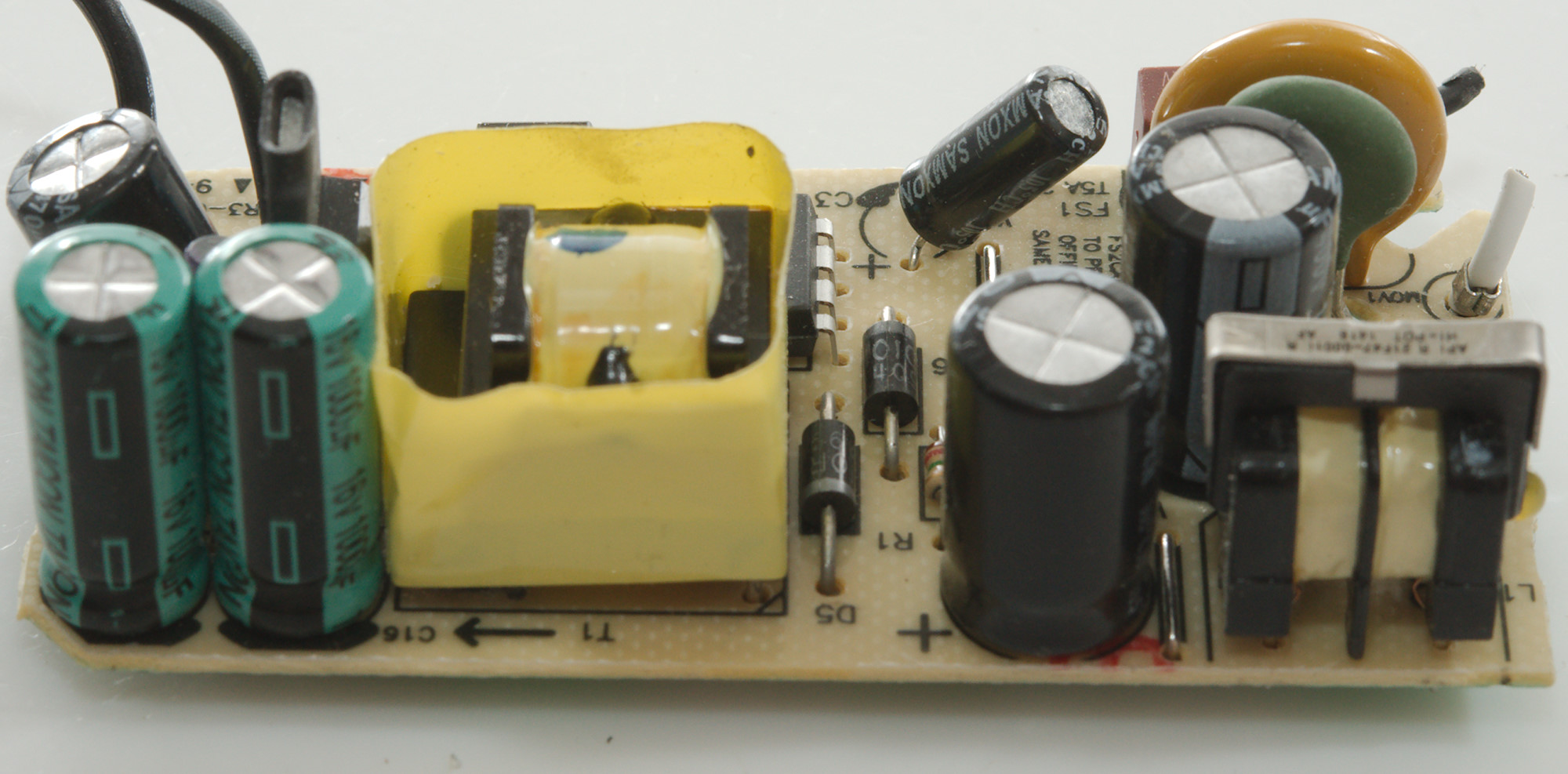
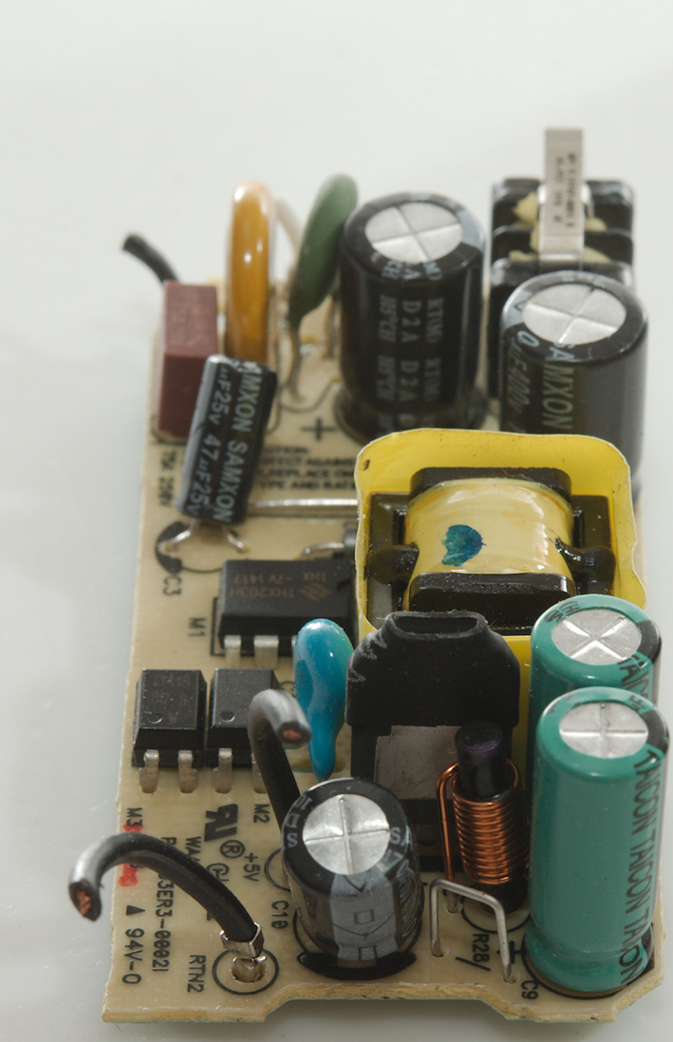
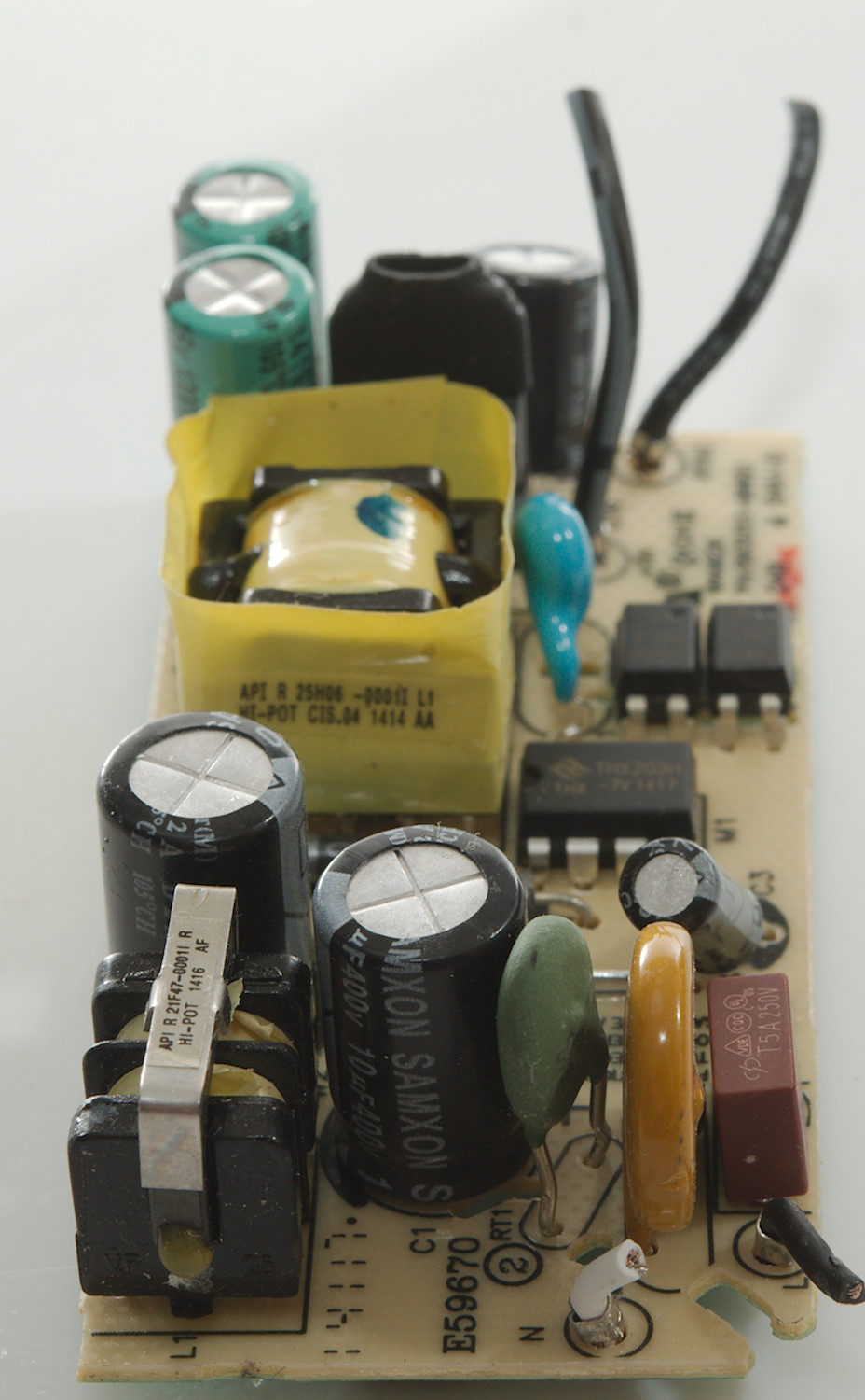
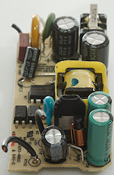
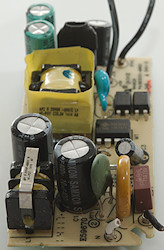
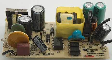
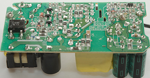
This power supply is nicely designed. At the mains input is a fuse (FB1), a transient protection (MOV1) and a inrush current limiter (RT1). There is also a common mode coil (L1), it is place between the two smoothing capacitors (C1 & C2). The switcher (M1: THX203H) is next the to transformer (T1).
Between mains and low volt side is a safety capacitor (C11) and two optocouplers (M2 & M3). On the low volt side is the the rectifier diode (D7) with two capacitors directly on the output (C9 & C16) with a inductor (L3) to the output capacitor (C10).

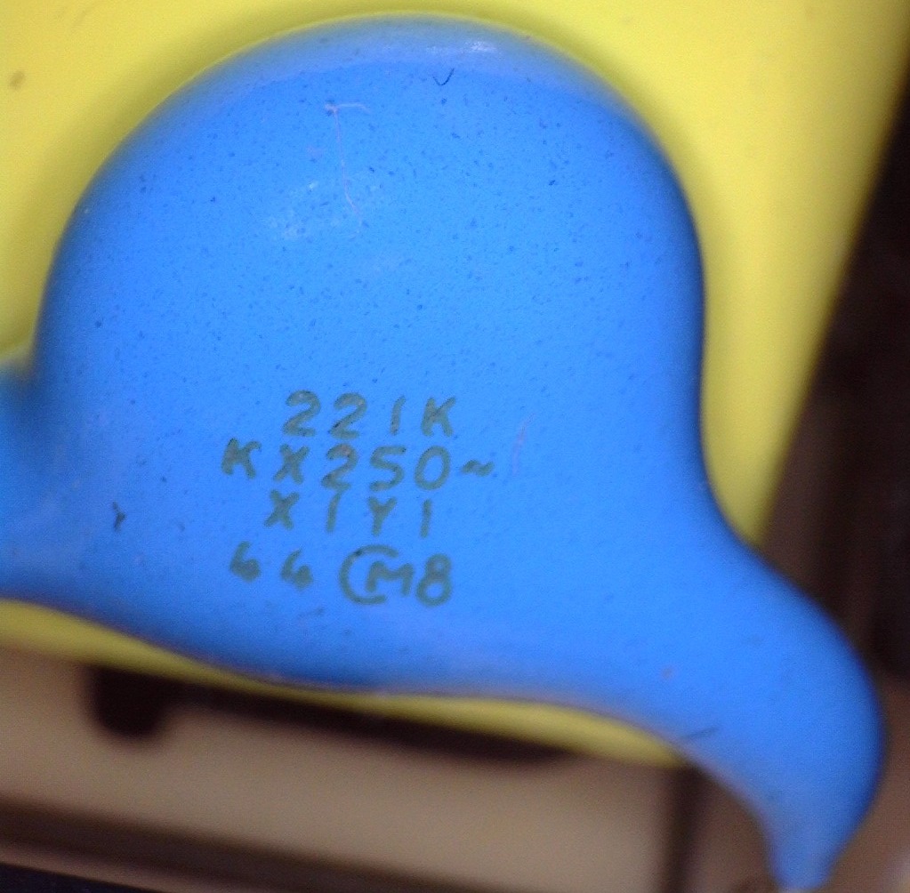
Lets take a close look at the safety cap. It says X1 & Y1, but I am missing a list of safety approval stamps?
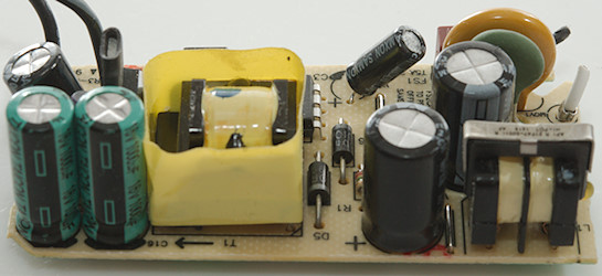
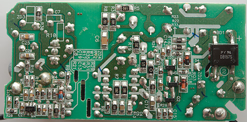
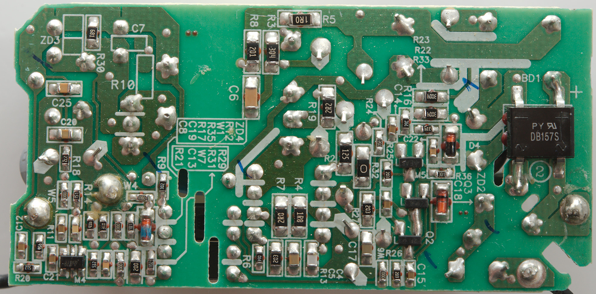
On this side is the bridge rectifier (BD1), there is two small transistors (Q2 & Q3) and a IC (M5). At the low volt side is a IC (M4) and a zener diode (ZD4), I wonder which of them is the reference, maybe the chip for normal regulation and the zener for overvoltage?
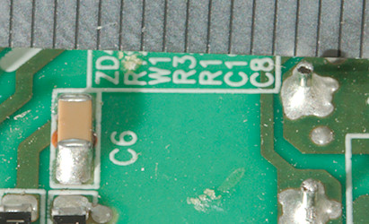
Here must be more than 6mm for the supply to be rated safe, it well above that.
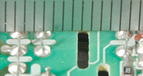
With a slot only 4mm is needed, but the actual distance is more like 6mm.
Testing with 2830 volt and 4242 volt between mains and low volt side, did not show any safety problems.
Conclusion
This looks like a good quality power supply with all the required filtering and safety (Maybe the safety capacitor is unapproved), it means the 5V output is stable (Except for cable compensation) and clean.
It is a good supply.
Notes
The power supply was supplied by a reader for review.
Index of all tested USB power supplies/chargers
Read more about how I test USB power supplies/charger
How does a usb charger work?