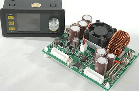
Power supply frontend DPS5020-USB 50V/20A with Bluetooth and USB interface
This device is the front end for a power supply, it must be supplied with low voltage DC power (Up to 60V).
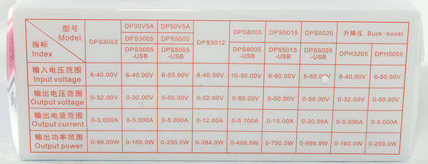
Official specifications:
- Input voltage range: 6.00-60.00V
- Output voltage range: 0V-50.00V
- Output current: 0-20.00A
- Output power range: 0-1000W
- Product Weight: about 222g
- Display module size: 79*43*38(mm) (L*W*H)
- Cutout size: 71mm*39mm
- Power module size: 93*71*41(mm) (L*W*H)
- Length of connecting line: 200mm
- Fixed hole center distance: 86mm, 64mm
- Output voltage resolution: 0.01V
- Output current resolution: 0.01A
- Output Voltage accuracy: ± (0.5% + 1 digit)
- Output Current accuracy: ± (0.5% + 2 digits)
I got it from aliexpress store: RD official store

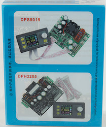

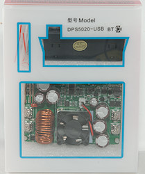
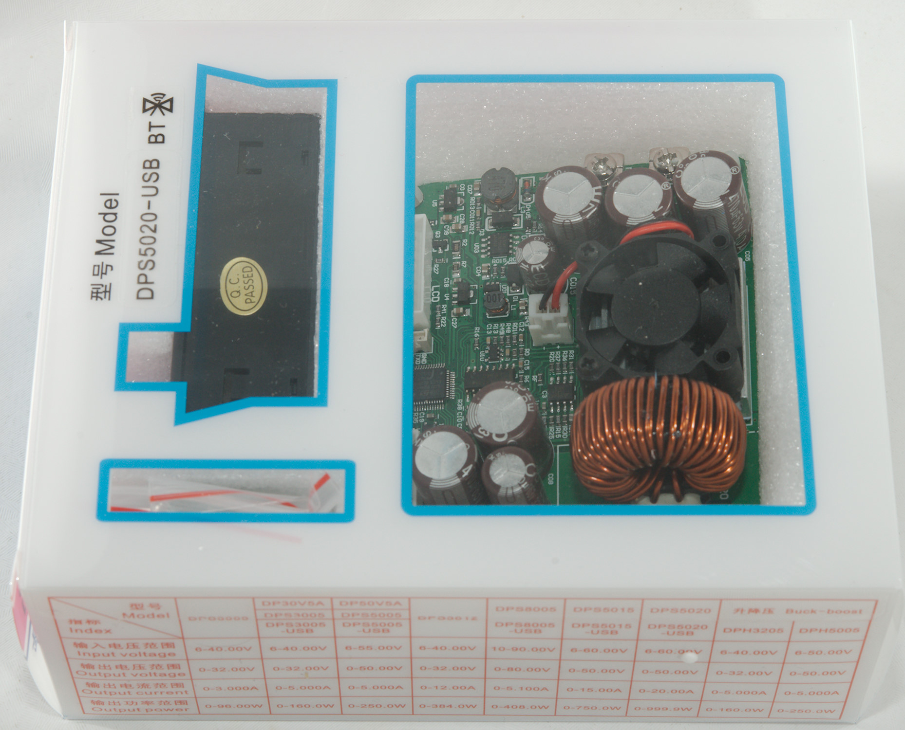
It arrived in a styrofoam box together with some other stuff, inside the box was the plastic box with the electronic.
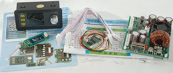
There is a control unit, a power unit, two flat cables, some rather small fork terminals, the usb interface, the Bluetooth interface, cable for usb/bluetooth and a manual in English and Chinese.
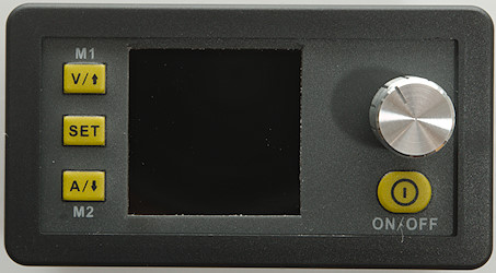
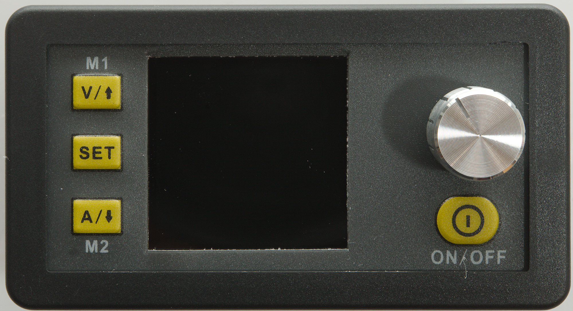
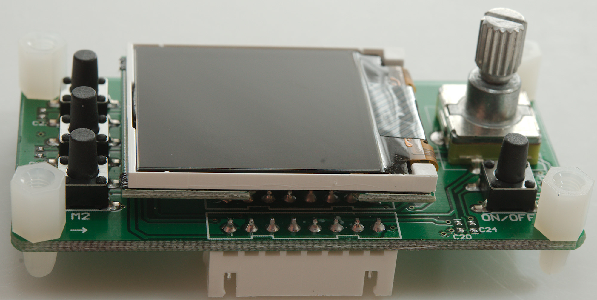
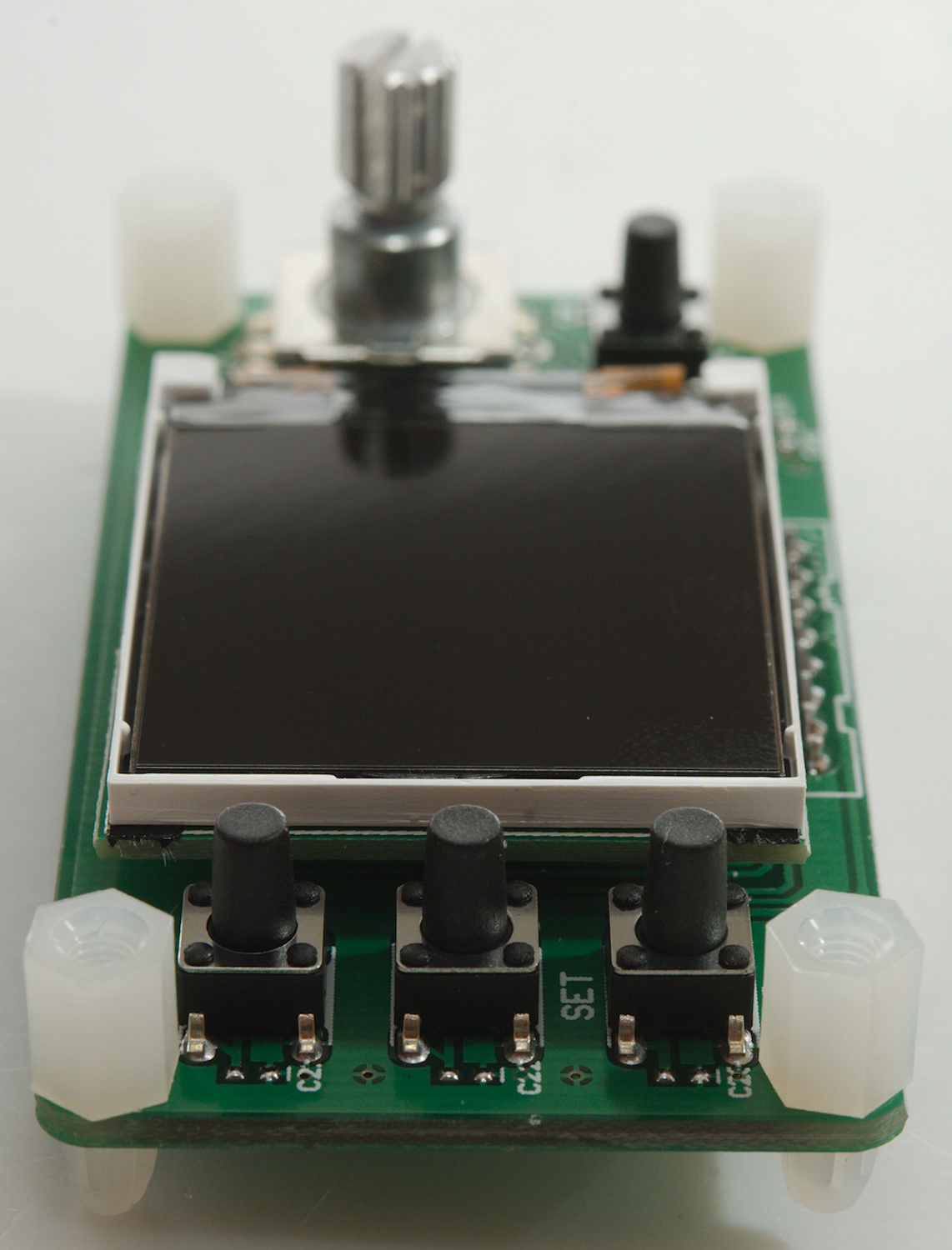
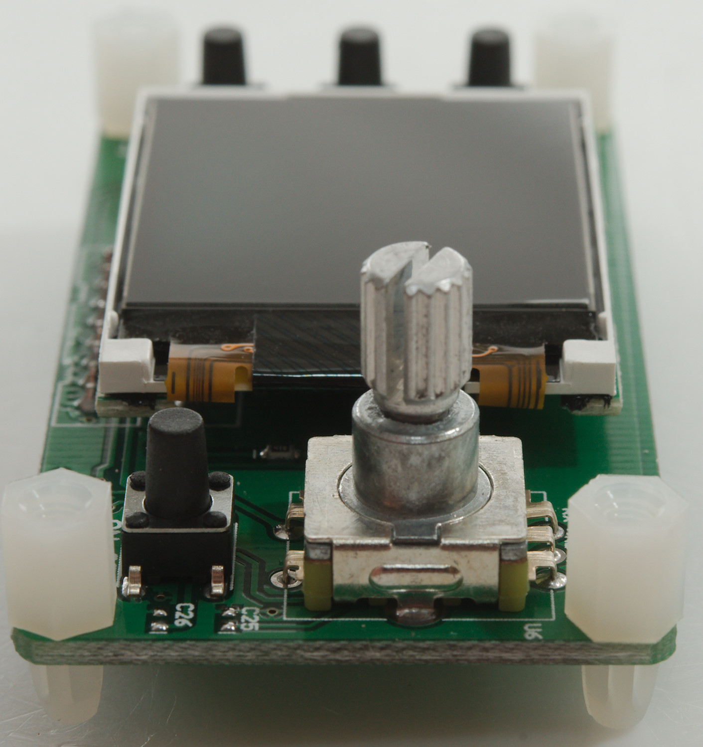
The control unit has a display, four buttons and a encoded that can be pressed.
The V and A buttons will enable adjustment of voltage and current with the encoder, press the encoder to select digit, when finished press SET.
Holding down V/A/SET will recall a preset, with V and A it is preset 1 and 2, with SET any of the 9 presets can be selected.
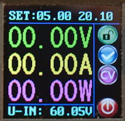
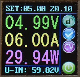
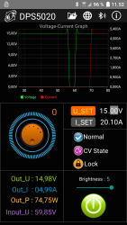
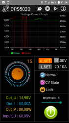
Display while off and on, set point is shown at the top of the screen and input voltage at the bottom.
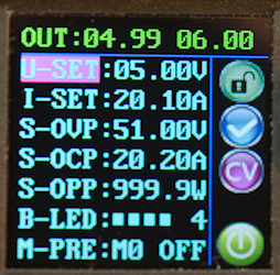
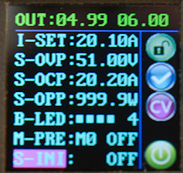
On the settings screen it is possible to define a couple of parameters: Voltage, current, over voltage, over current, over power, display brightness. The "over" settings will turn output off if they are reached.
The device has 9 preset memories. To save a preset adjust the parameters, move the marker to M0, adjust the encoded to desired preset number and hold down the SET button.
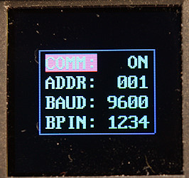
There is a hidden communication menu, hold down the "V" button while powering on the supply to activate it (Default is fine for most applications).
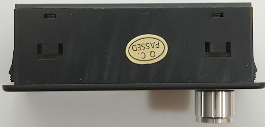
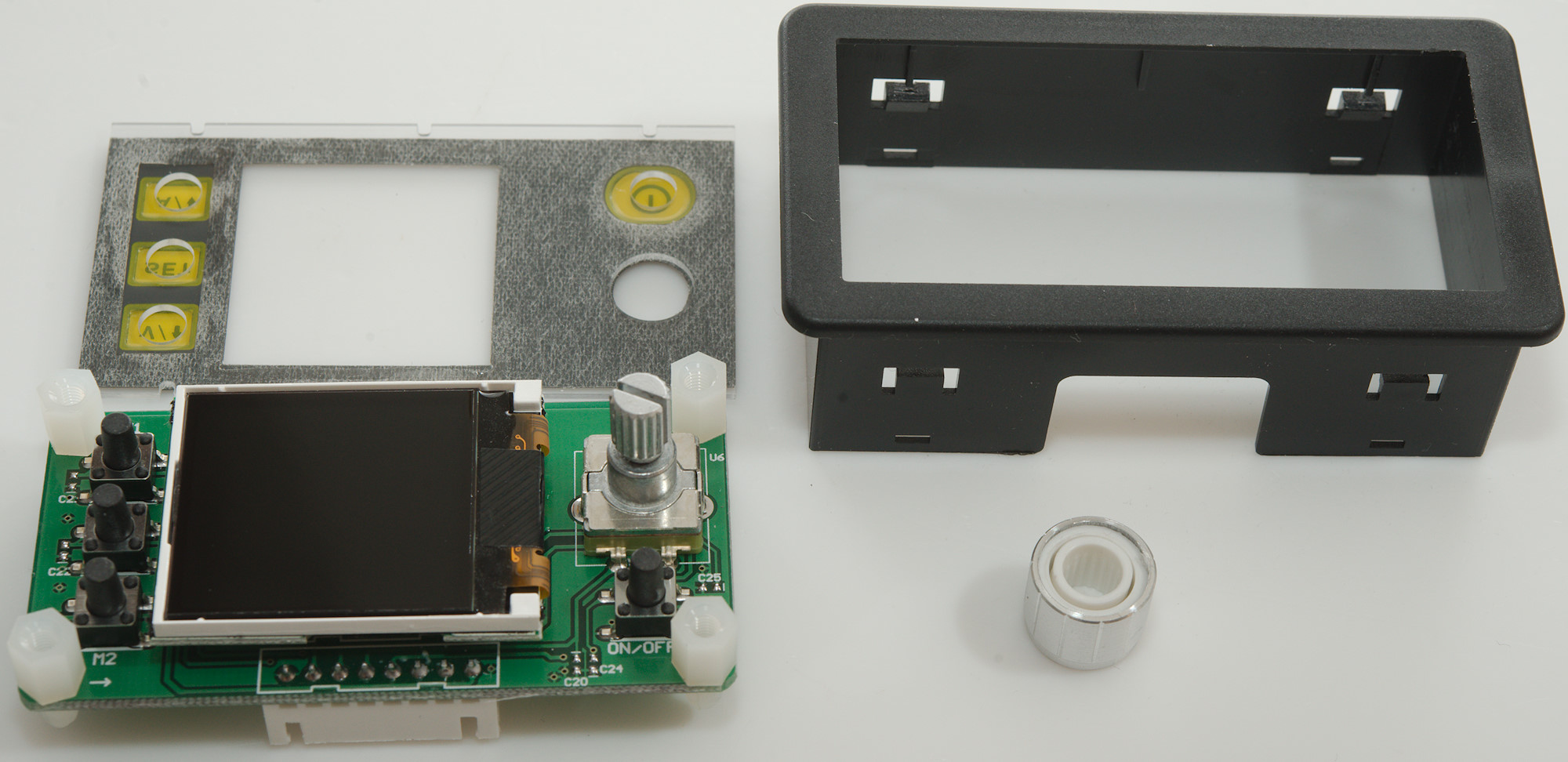
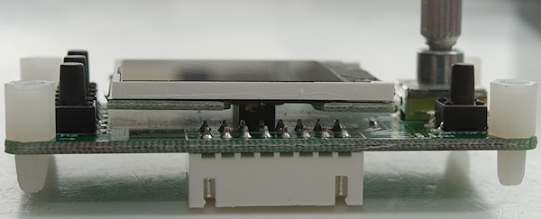
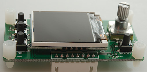
The front panel is made to be pushed into a rectangular cut-out
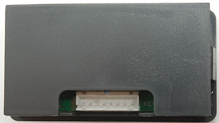
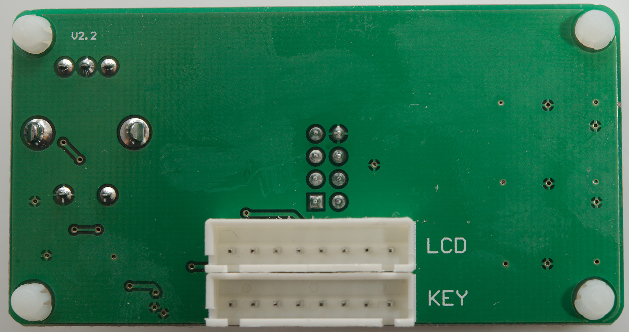
The two flat cables from the power unit is connected at the back.
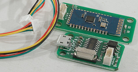
The Bluetooth and USB modules are small circuit boards and a wire to connect one of them (It is only possible to connect either Bluetooth or USB module to the power module).
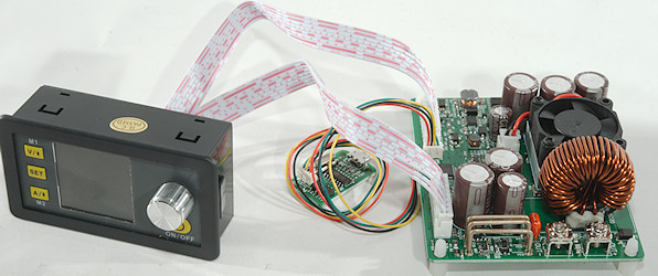
Wires connected, ready to test.
Measurements
I did a huge amount of test on this unit and will only show a few of the charts here, I have posted more in another article.
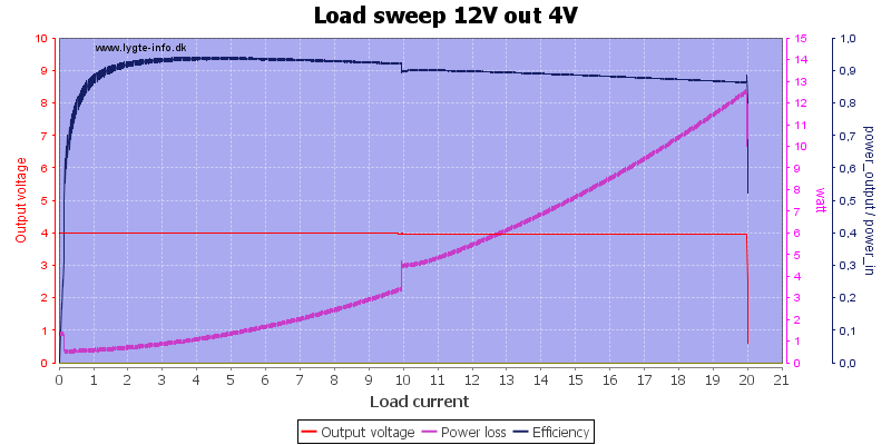
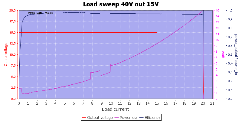
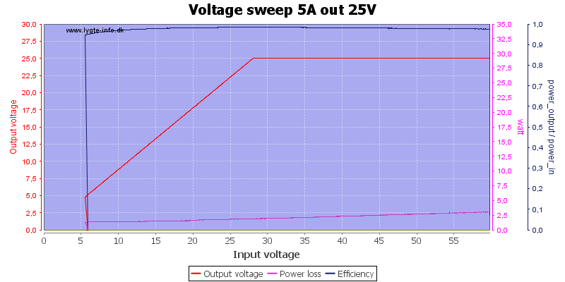
Running at low input and output voltage, the output looks stable and the fan starts at 10A.
Increasing both input and output voltage, this time the fan starts earlier, probably due to a temperature sensor. The power lost in the unit is higher, but efficiency is better.
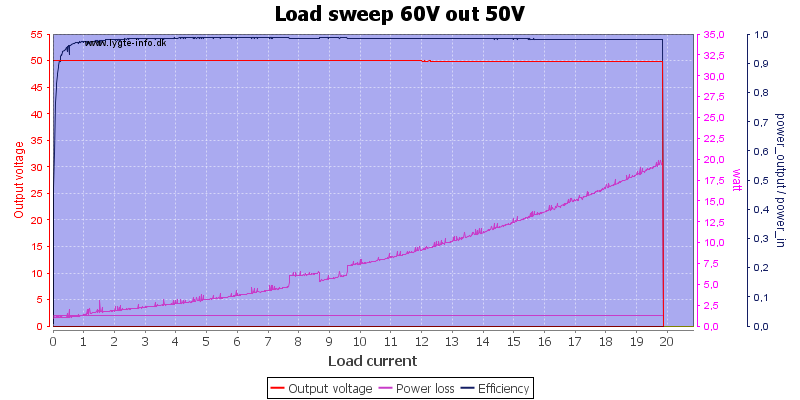
Here I run at maximum input and output voltage, this means up to 20W lost in the supply, but that is not much when the output power is 1000W
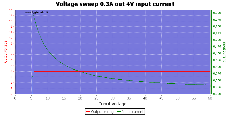
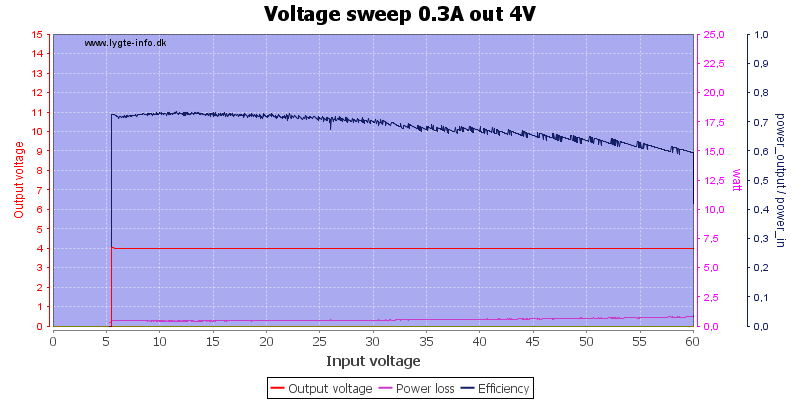
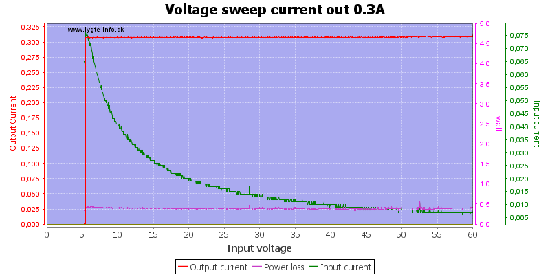
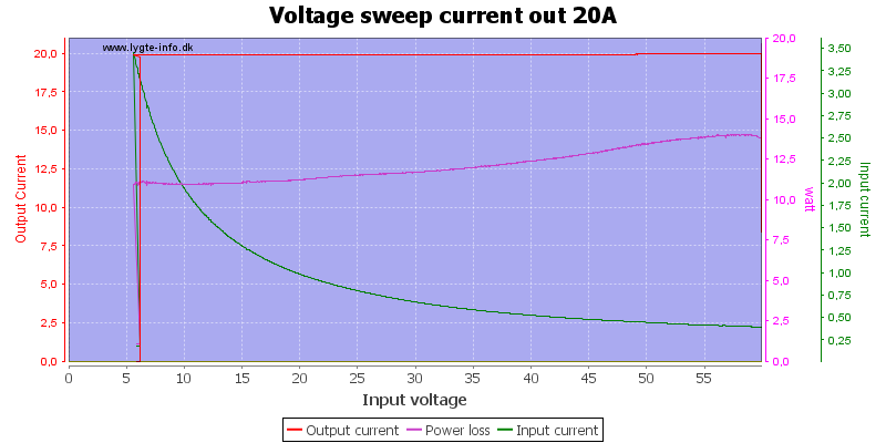
With very low output current and voltage it can maintain output voltage down to about 6V, at 20A it needs about 1 volt mere (Some of it due to losses in the input wires and connections).
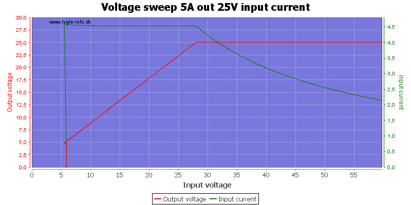
The specifications says it needs about 10% more input voltage than output voltage, it looks fine here.
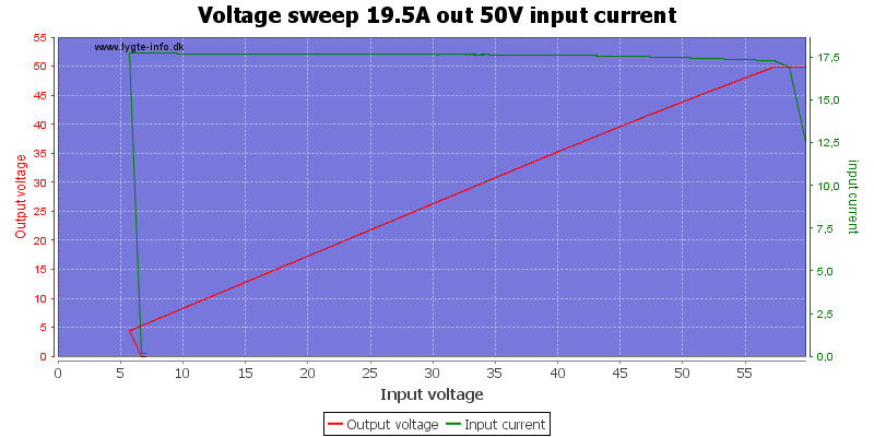
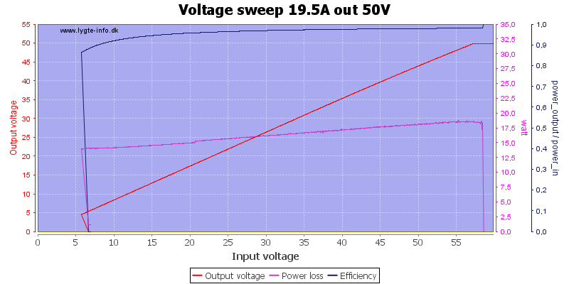
At full power output the input must be slightly mere than 10% above output voltage.
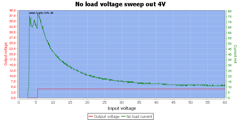
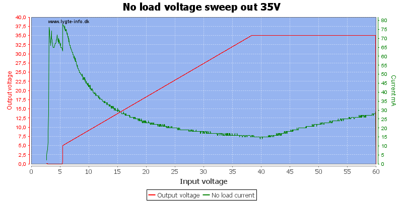
Current consumption depends on select output voltage and input voltage, but it is fairly low, even though it has to drive the display.
The power supply will go into constant current mode when overloaded, here I shorted the output and measured the current.
It can even be used as a 20A constant current generator.
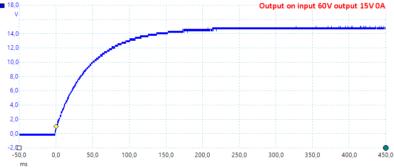
The output turns on without any spikes.
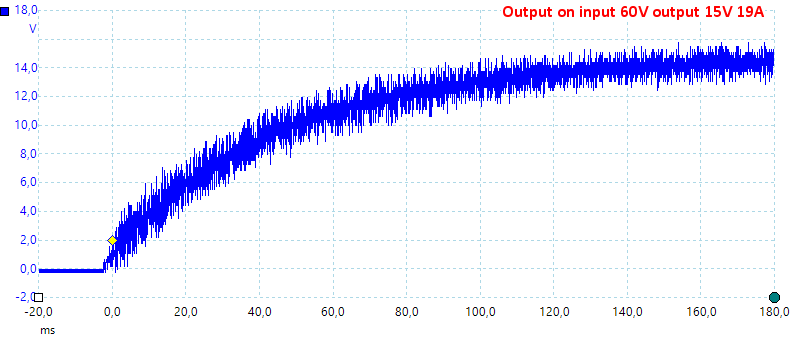
When loaded there will be some noise.
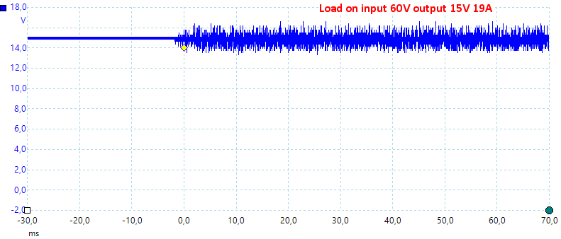
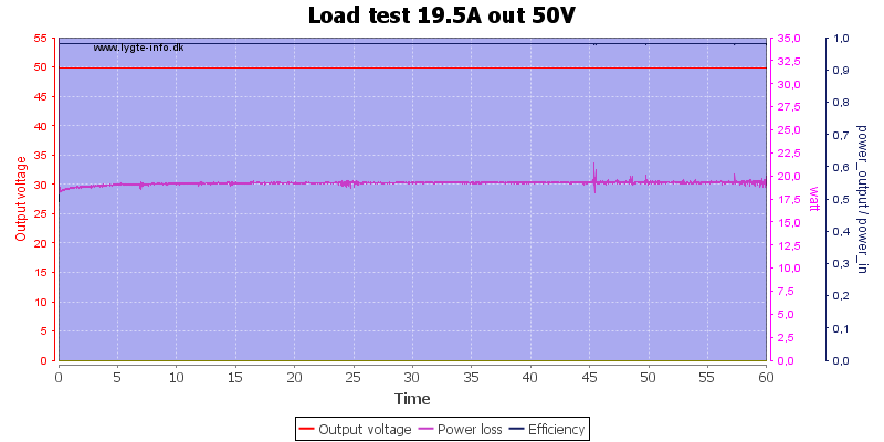
Changing the load from 0A to 19A do not show any voltage drops.
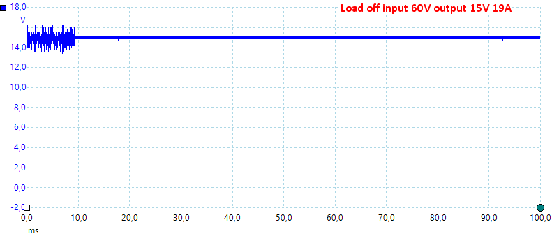
Changing the current from 19A to 0A do not show any voltage spikes.
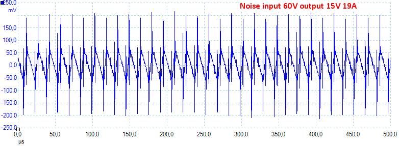
Both at low and high current there is some noise from the switcher on the output.
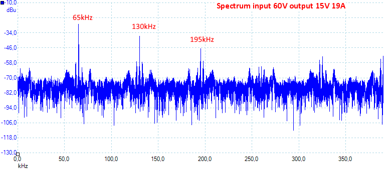
The switcher is running at about 65kHz.
It was no problem running at full output power for one hour (Except it heated my room).
After about 45 minutes I took the temperature photos below.
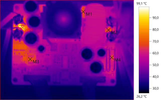
M1: 68.2°C, M2: 67.3°C, M3: 69.3°C, M4: 71.5°C, HS1: 99.1°C
The input fuse (HS1) gets rather hot at this current, the output fuse (M2) not as much. The internal power supply (M3) also warms up.
None of it looks problematic.
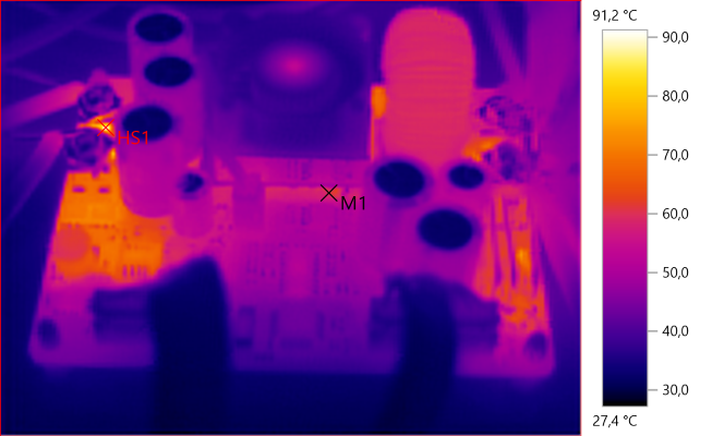
M1: 60.4°C, HS1: 91.2°C
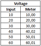
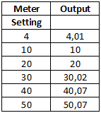
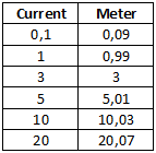
The display is precise and there is very little change with load.
Specifications says unit can be used as a charger, but there is a few problems with it:
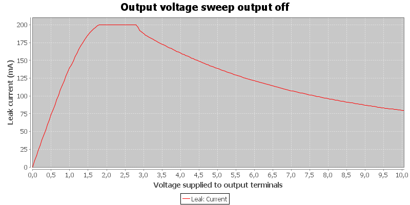
Power supply has input power, but output is off. A battery will be discharged with up to 200mA
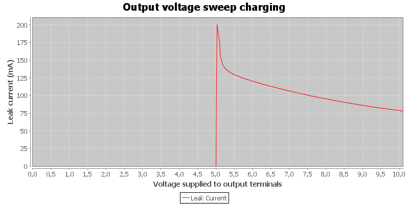
Power supply is supplying 5V output, if the battery voltage is higher than the selected voltage it will drain the battery.
The charge current is not shown in this chart, it is below the 0 line.
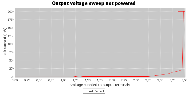
Power supply do not have input power, it will drain with more than 200mA from about 3.5V
Android application
- Application will show an ad for another RD product when started.
- Application is not on Google.
- RD uses a file download service that opens ads in minimized windows.
- Protocol is documented.

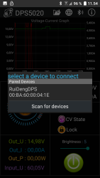
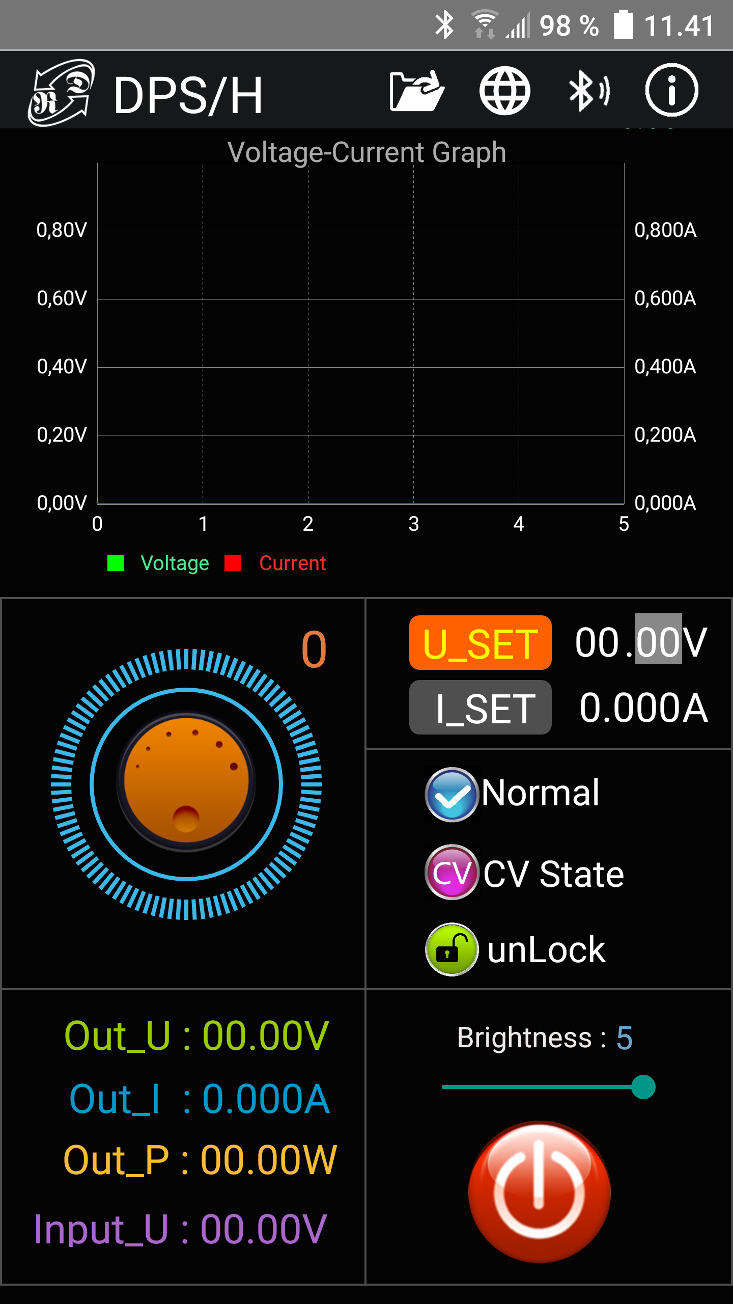
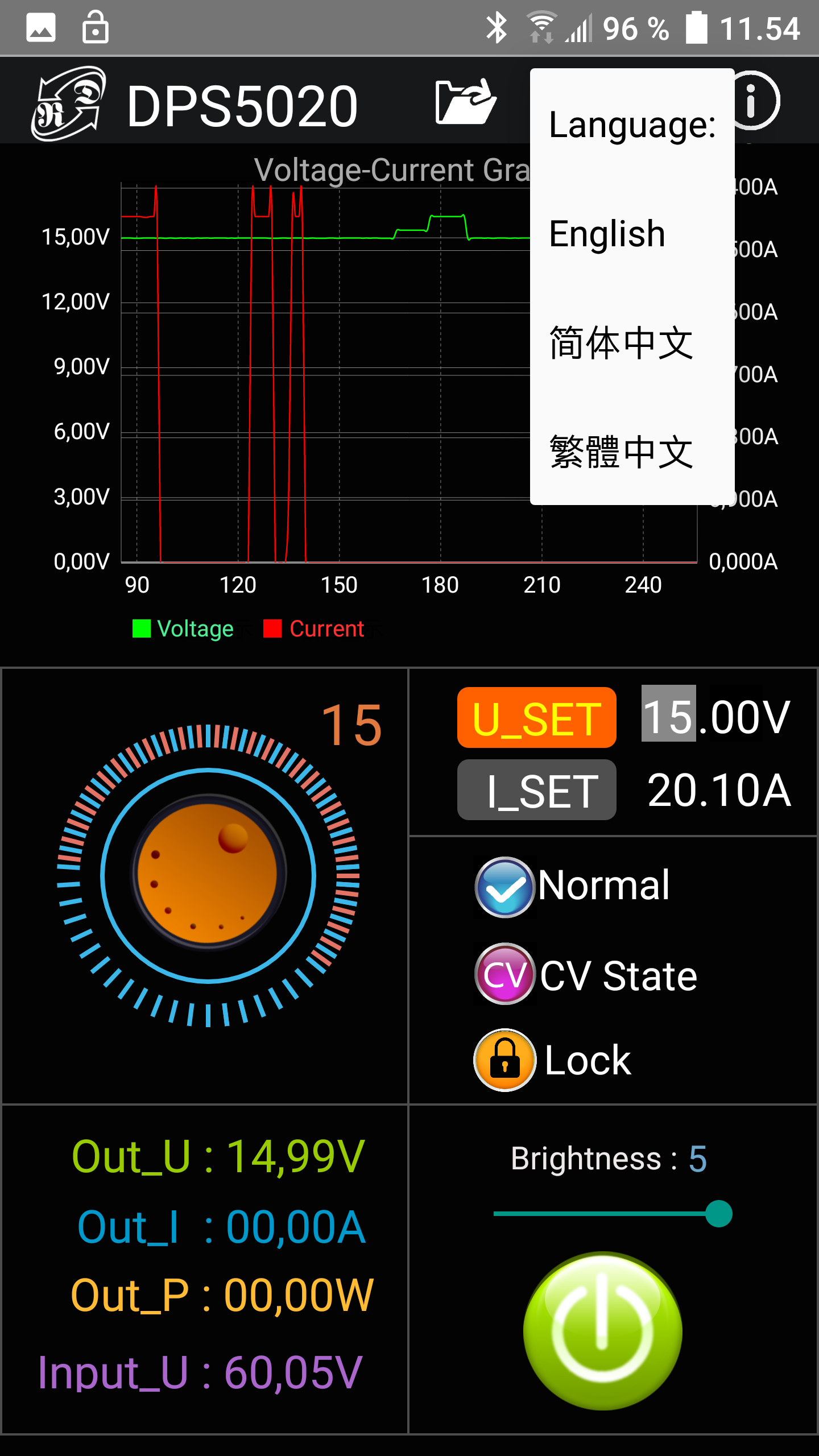
The application is basically one screen. To connect use the Bluetooth symbol, in my case I could not see the power supply and had to use the normal Android discover dialog (I did use "Scan for devices), after that it worked perfectly.
Here I am connected. I changed a setting and saw the voltage dropout on the chart. After that I connected my oscilloscope, but did not see any dropout on the chart or the scope.
The wheel is used to adjust voltage and current with, but only two digits at a time. Touch the U_SET/I_SET and digits to select what two digits to adjust.

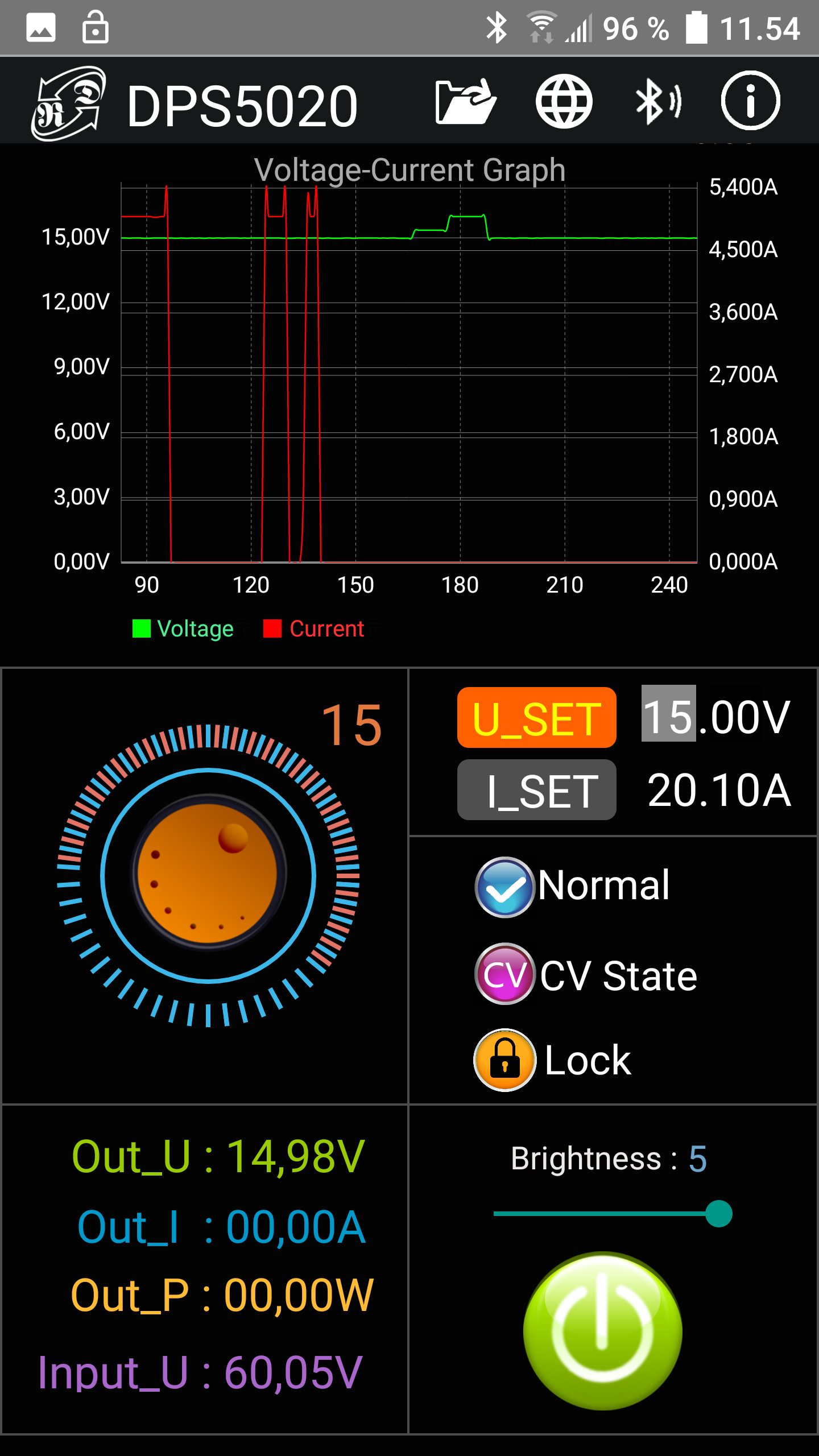
The control panel is locked while using the phone and it is not possible to unlock it. I would have preferred that at least on/off worked.

There is not many languages in the current version of the application.

Using the file folder will save a Excel file on the phone with a fixed name, i.e. it is only possible to save one log.
PC application
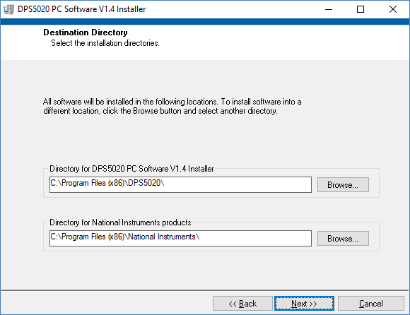
- Application is a 240MB download
- Inside the archive is manuals, a font, a driver and another archive with the program
- Application is very slow to install.
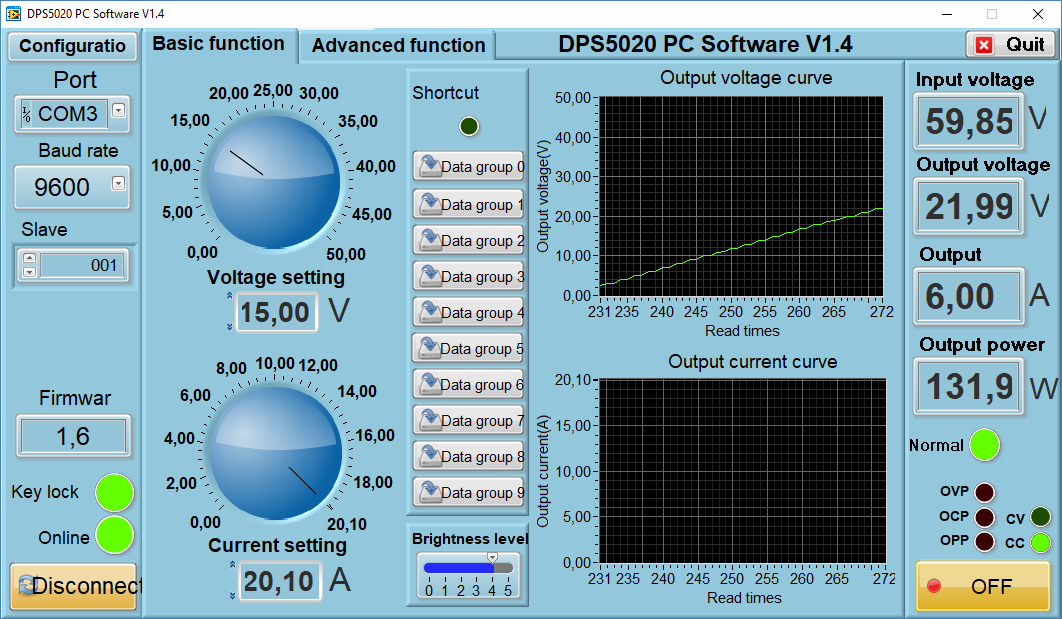
- The screen is a fixed size (1062 x 619 pixels), there is no resize options.
- RD uses a file download service that opens ads in minimized windows.
- Protocol is documented.
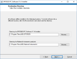
The package uses a National Instruments library, this is large and slow to install. This installation will not install the supplied font, it has to be installed manually. The letters are a bit to large without that font.
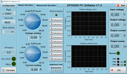
Program started, but not connected yet.
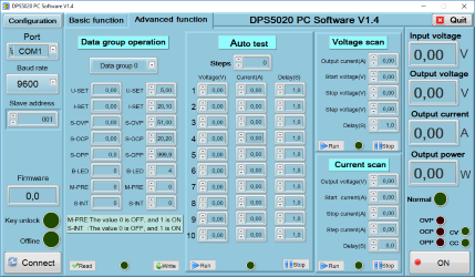
The advanced tab where the presets can be configured and 3 types of automatic sequences can be defined and used.
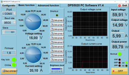
When connected the actual values and curves are added. The dials can be changed with a mouse or new values can be typed in the numeric fields.
On this screen the text do not fit into the boxes, this is partly my own fault, because I did not install the supplied font. Why do the installer not handle that?

I did some voltage scans, here it is seen from the program.
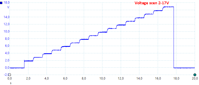
And here with a oscilloscope (Parameters are not the same).
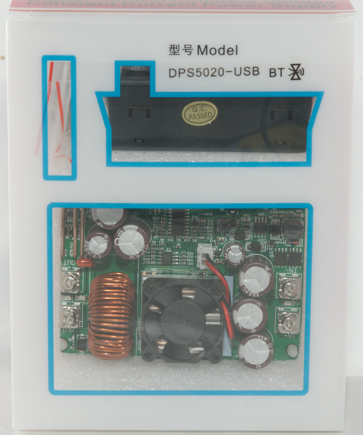
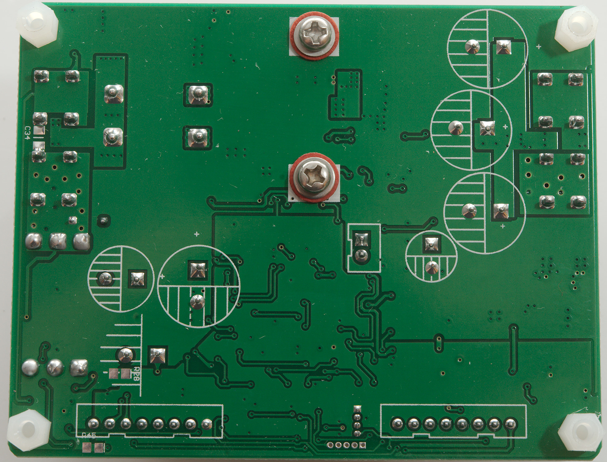
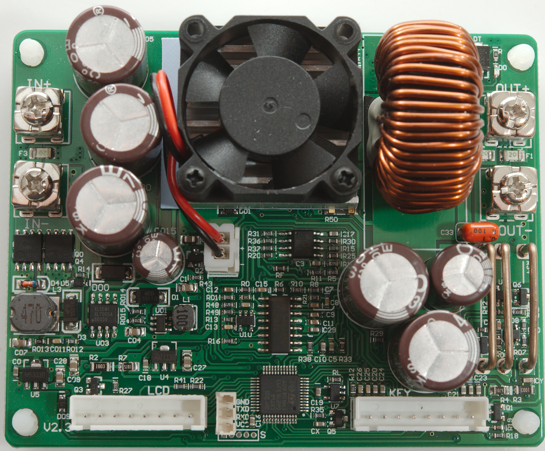
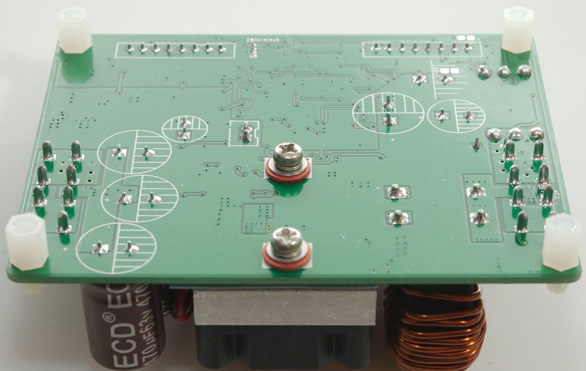
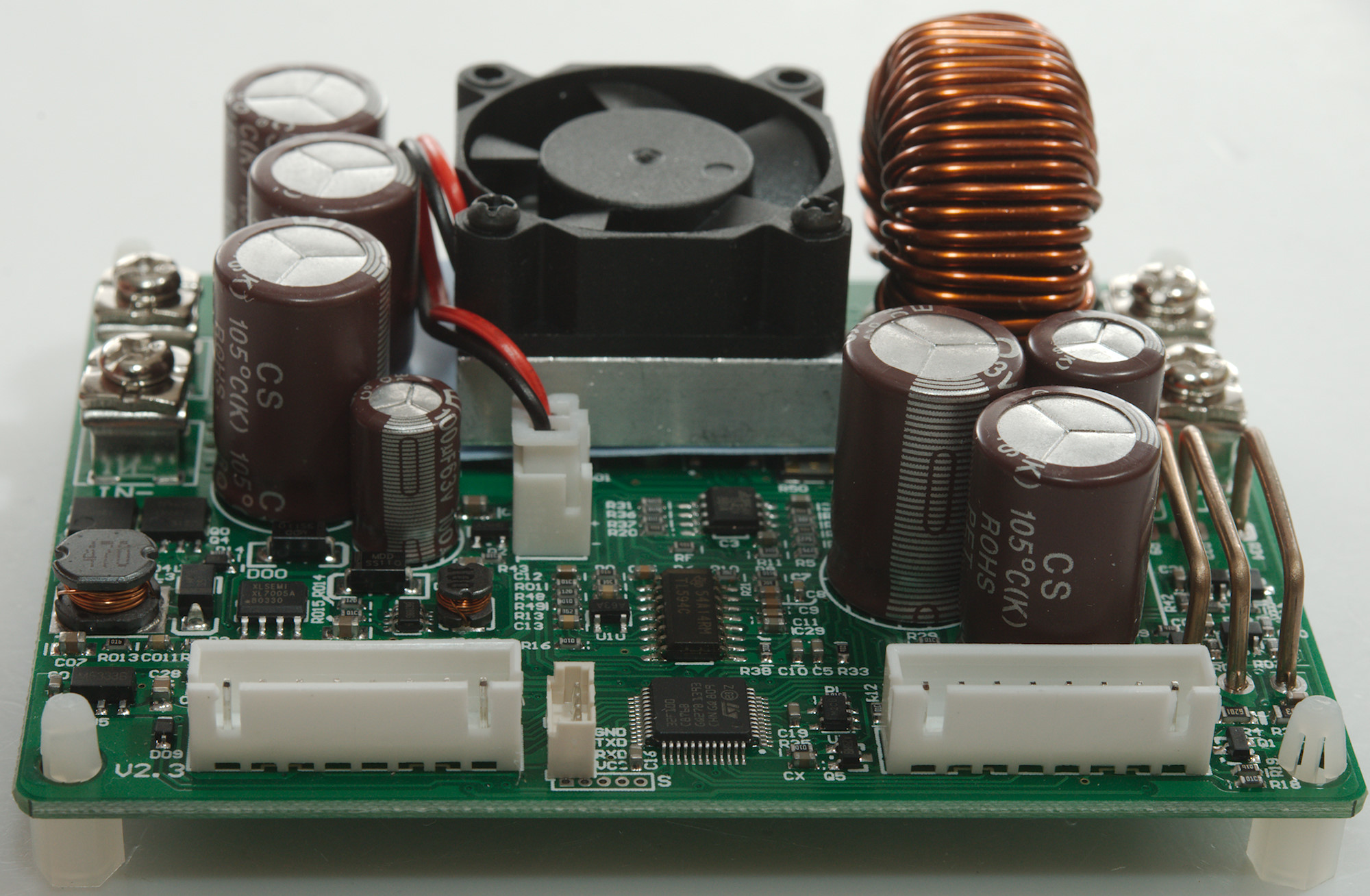
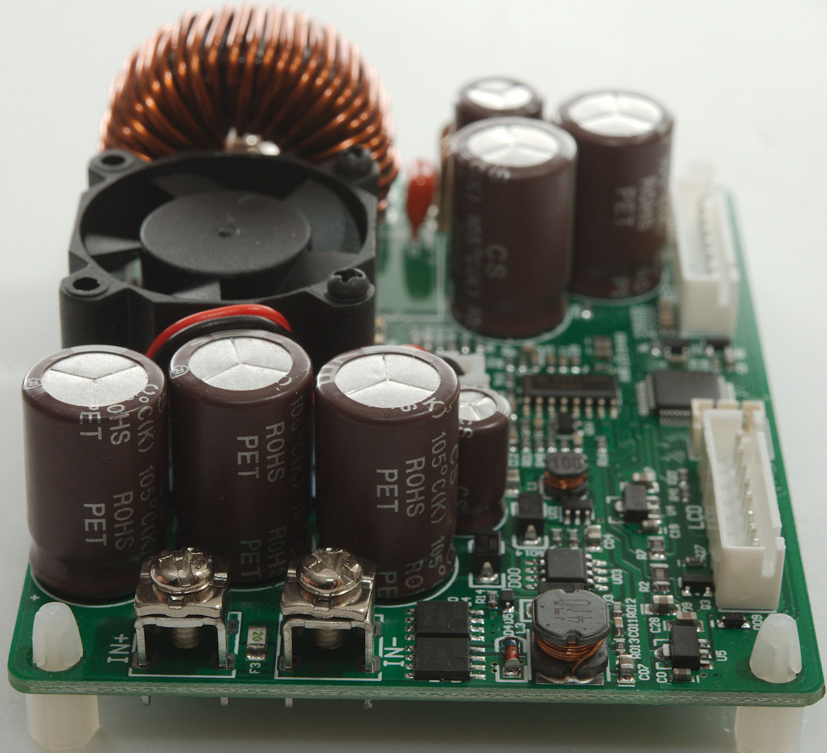
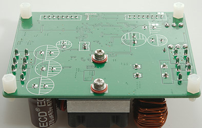
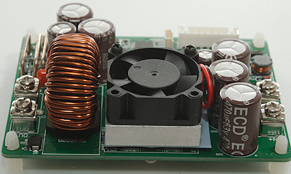
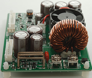
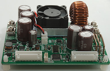
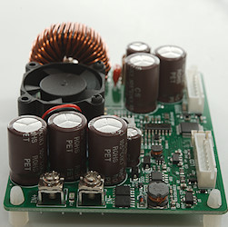
A closer look at the electronic
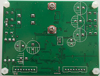
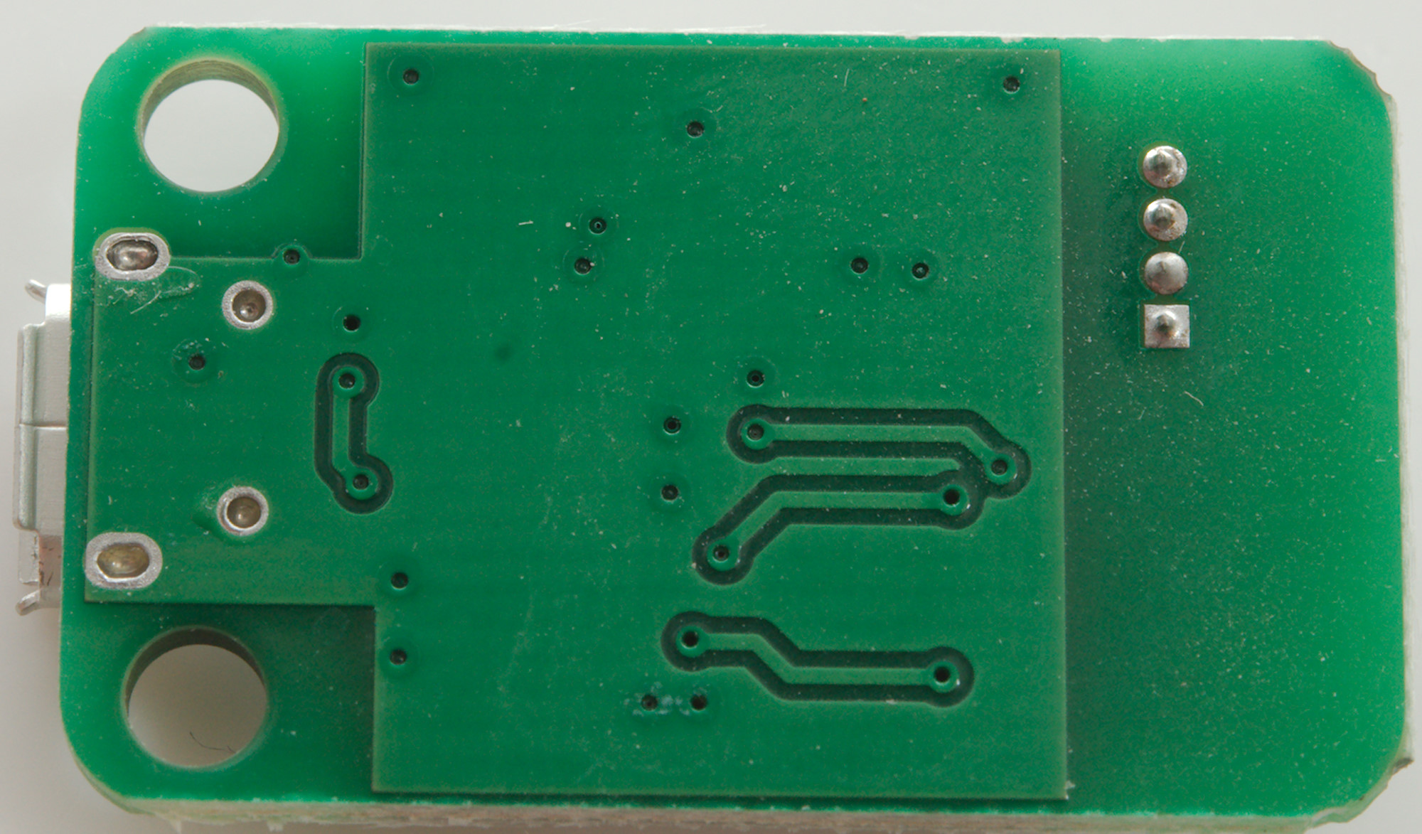
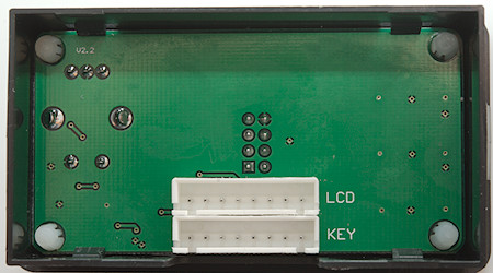
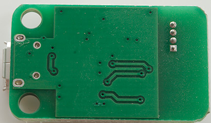
This side of the circuit board is only soldering, screws and some standoffs.
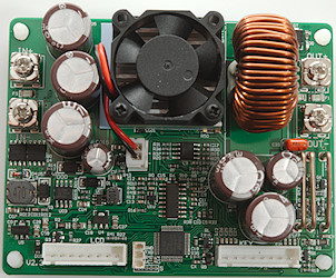
All electronic is on this side. At the input is a 20A smd fuse and two high power mosfet (Q0 & Q4). The switcher is a TL594 and next to the heatsink is a high speed and precision OpAmp. The microcontroller is a 32F100. The board do also have a internal switching power supply (U03: XL7005A) and some linear regulators. The output has two 20A fuses in parallel.
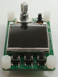
Front panel
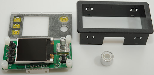
The front panel uses four clips to keep the circuit board in the box.
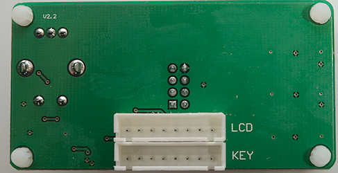
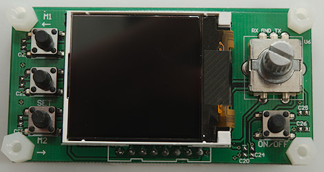
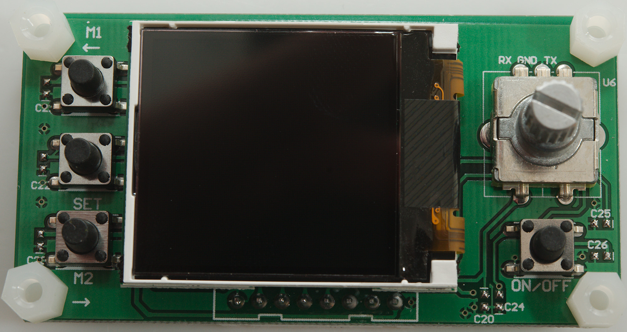
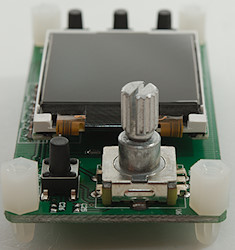
The circuit board has mechanical switches, a encoded and the display.
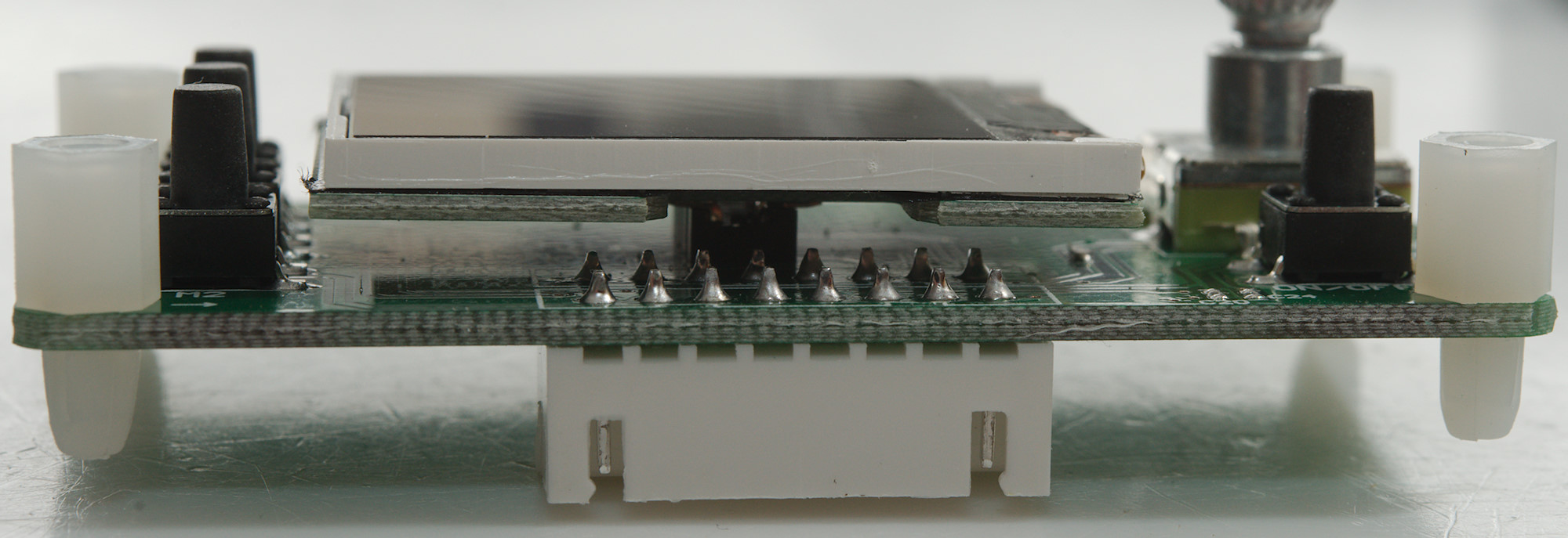
There is nothing hidden under the display.
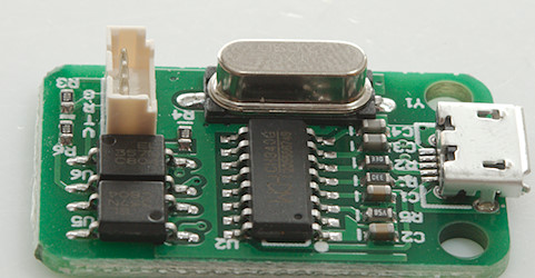
USB module
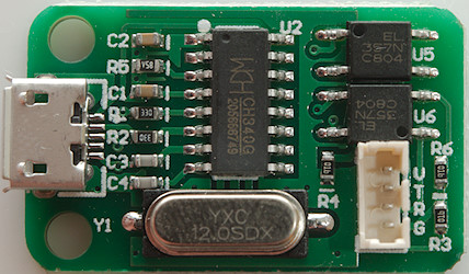
The usb module uses a CH340 chip and two optocouplers.
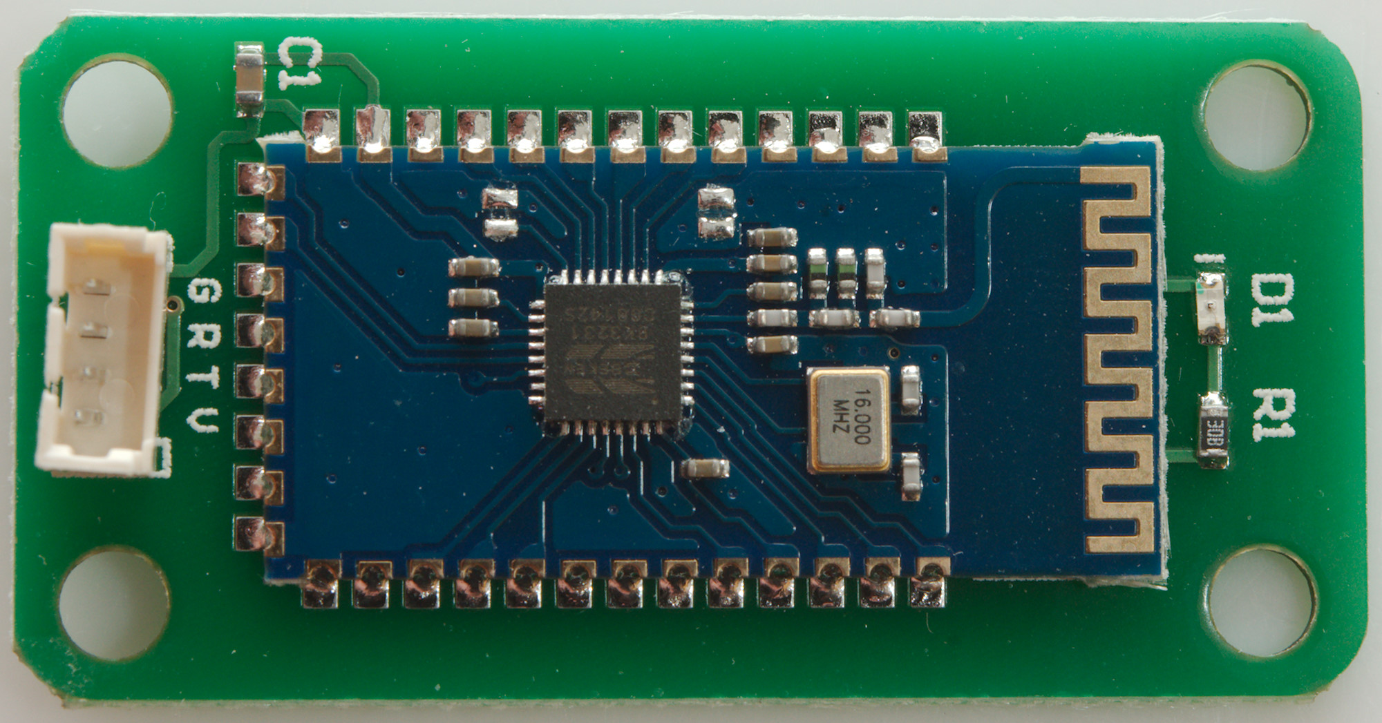
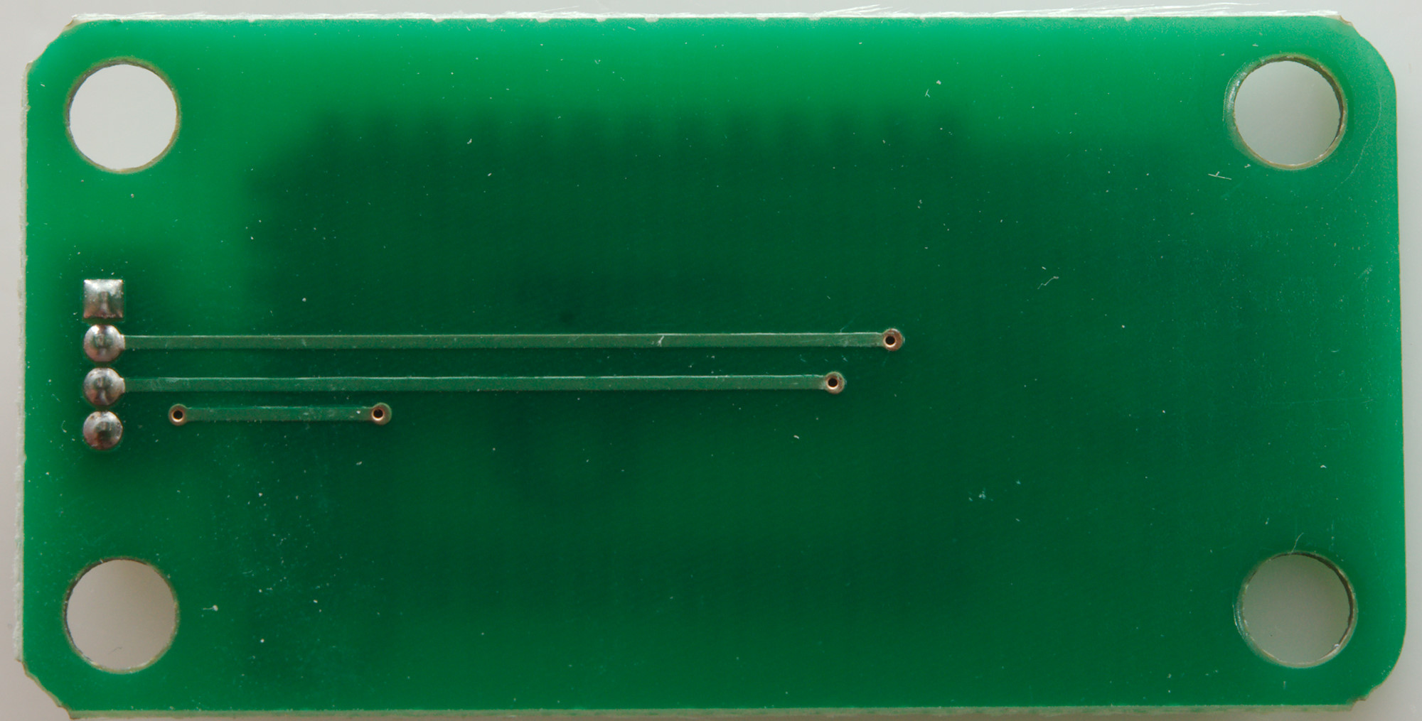
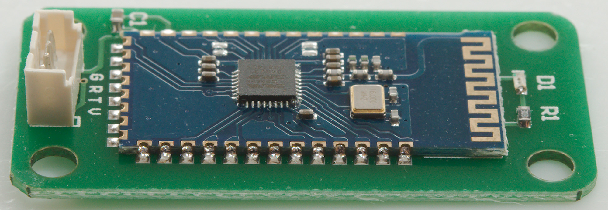
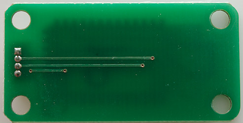
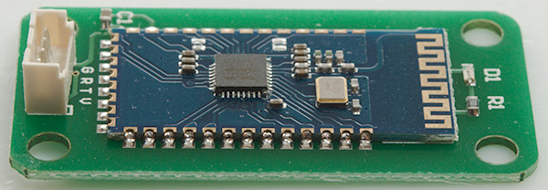
Bluetooth module
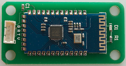
The Bluetooth module is a Bluetooth module and a led.
Conclusion
This module can deliver a lot of current and power when supplied with enough DC input power. The PC option may not be very nice looking, but it has some interesting functions on the advanced tab and I like the protocol is documented. The phone app has a very nice graphing and logging function, but adjustment of voltage and current is not that good.
This module is very useful to build a cheap high power bench power supply with. Add a cheap switching power supply, a box (RD sells one), some binding posts and some work.
Compared to professional units it is missing a lot: Lower noise, both numeric keypad and encoded, 4 terminal connections, larger display. But for the price it is very good and works fine.
Notes
The power supply was supplied by RD for review.