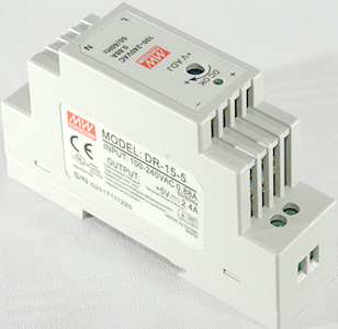
MeanWell 5V 2.4A Din Rail Mount DR-15-5
Official specifications:
- DC voltage: 5V
- Rated current: 2.4A
- Rated power: 12W
- Ripple & Noise: 80mVpp
- Voltage adj. range: 4.75V | 5.5V
- Voltage tolerance: 2%
- Line regulation: 1%
- Load regulation: 1%
- Input voltage range: 85V ~ 264V
- Efficiency: 77%
- Overload: 105 ~ 160% of rated output over.
- Over voltage: Shut off, clamping by Zener diode.
I got it from ebay dealer lucky-bird2011
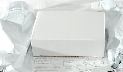
This power supply arrived in a unmarked box inside an envelope.
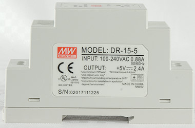
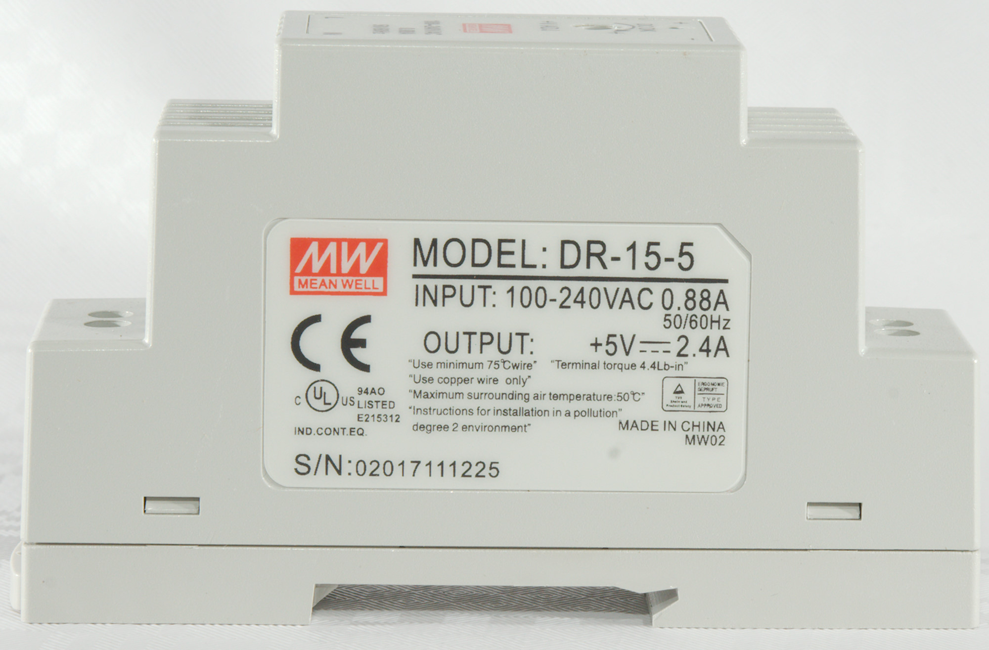
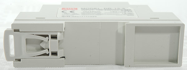
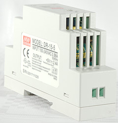
Type number and specifications are clearly marked on the outside.
The UL file number is for motor mounted equipment, according to MeanWell this supply has UL number E183223, not E215312 as listed on it.

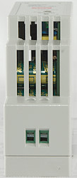
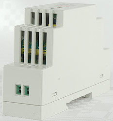
Connections are done with screw terminals and there are holes for ventilation.
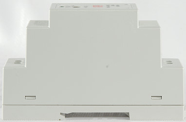
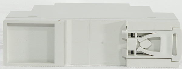
The DIN rail mounting.
A nice detail is that it is also locked in open position.
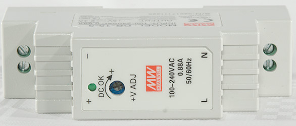
On the top is a minor voltage adjustment and a led to indicated output power is present.
Measurements
- Power consumption when idle is 0.19 watt
- Default output voltage 4.99V
- Minimum output voltage 4.37V
- Maximum output voltage 5.25V
- Weight: 86g
- Size: 94 x 56.2 x 24.92mm
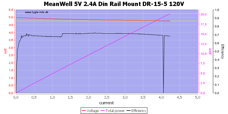
The voltage drops with load and the overload protection first kicks in above 4A (Specifications says between 2.52 and 3.84A).
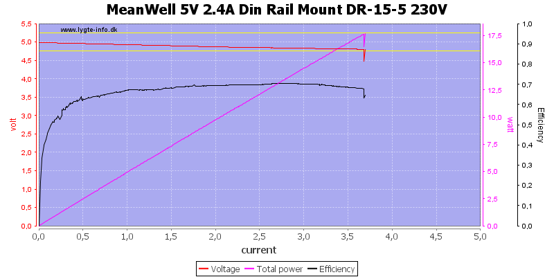
Using 230VAC brings the overload protection within specified range, but it is supposed to work from 85V to 264V
The efficiency is around 70%, not the rated 77%.
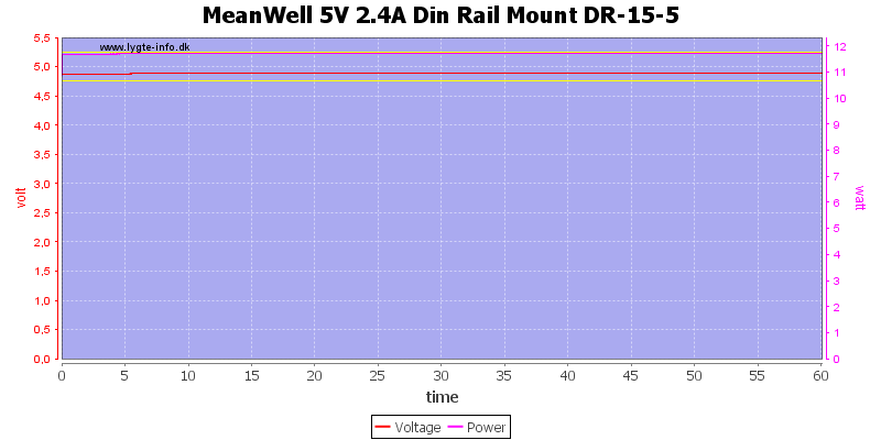
Running the power supply with 2.4A current for one hour worked, but it got hot.
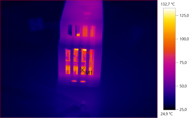
The temperature photos below are taken between 30 minutes and 60 minutes into the one hour test.
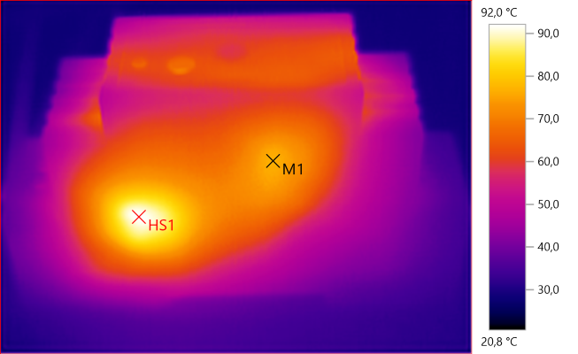
M1: 76.5°C, HS1: 92.0°C
HS1 is the rectifier diode and M1 the switcher.
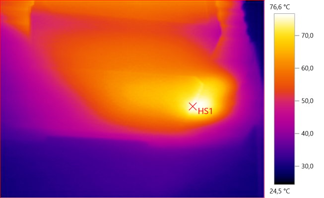
HS1: 76.6°C
The rectifier is also hot from this side.
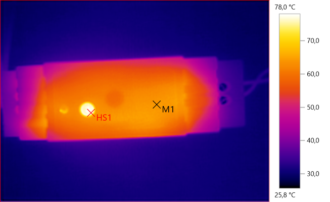
M1: 63.9°C, HS1: 78.0°C
M1: 101.1°C, HS1: 132.7°C
HS1 looks to be the transformer and M1 the capacitors (Rated 105°C). The capacitors are heated by the rectifier diode.
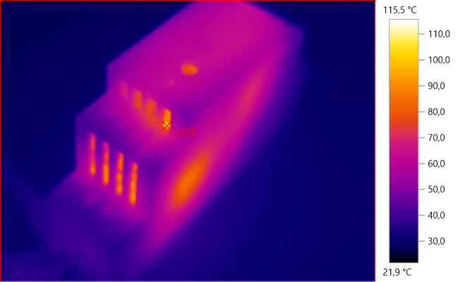
HS1: 115.5°C
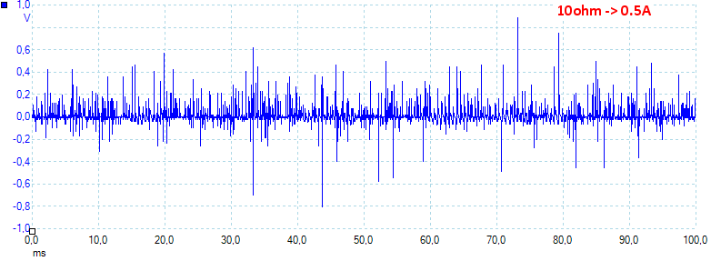
At 0.5A the noise is 60mV rms and 1772mVpp.
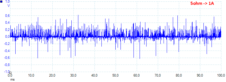
At 1A the noise is 64mV rms and 1896mVpp.
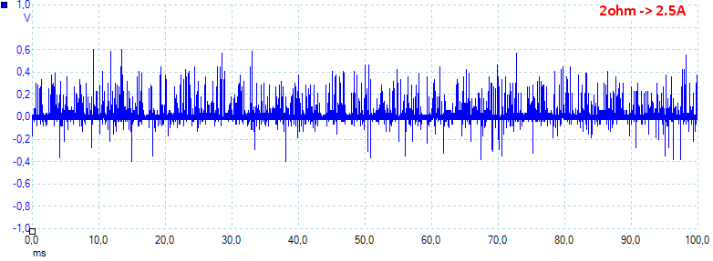
At 2.5A the noise is 75mV rms and 1098mVpp.
Tear down

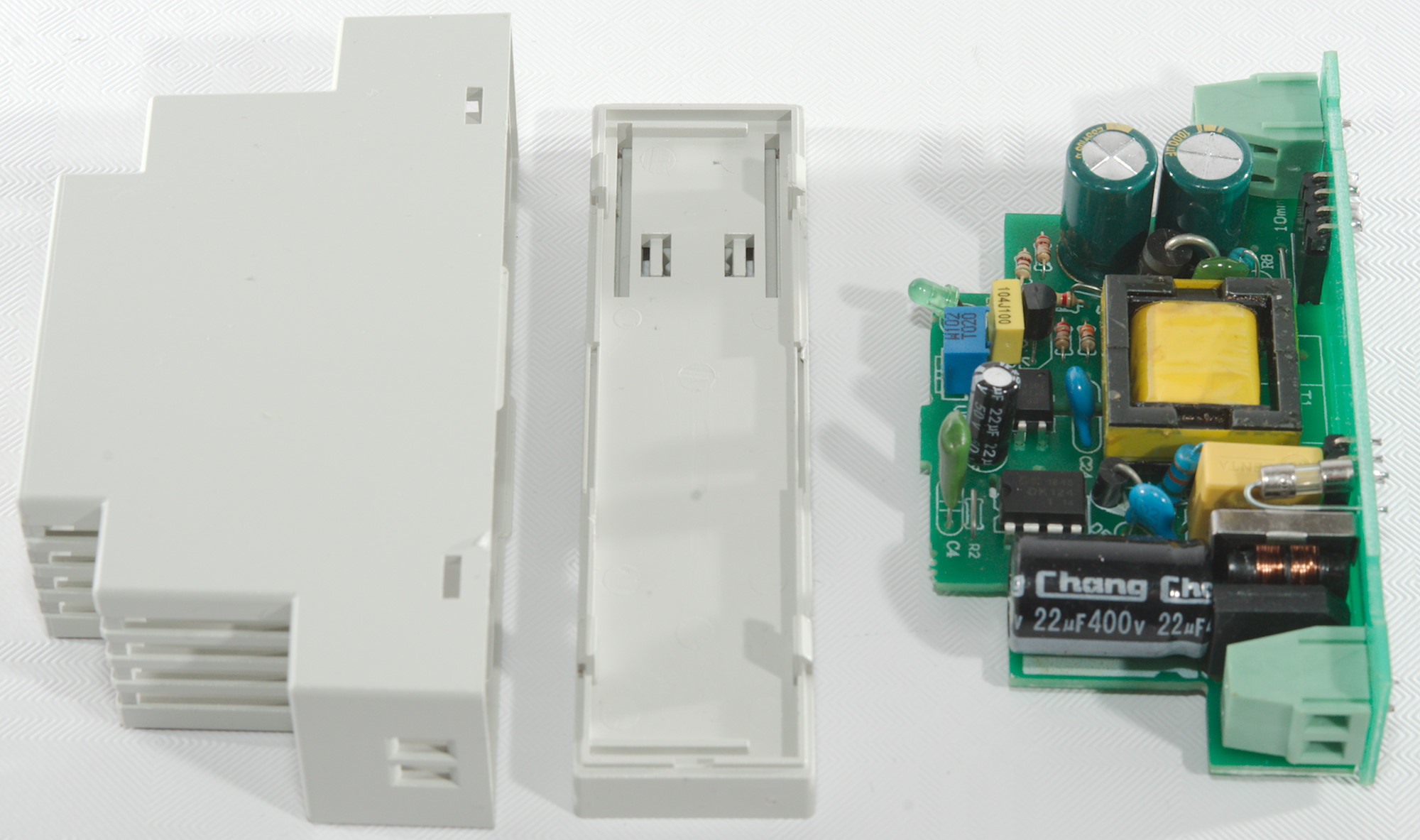
The supply is closed with clips and it could be pulled apart with a spudger.
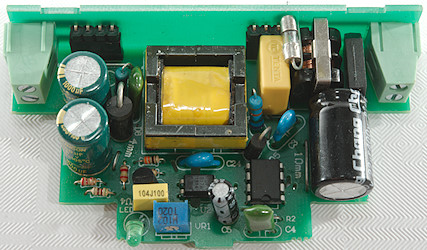
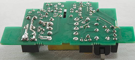
The construction is two circuit board mounted together with connectors.
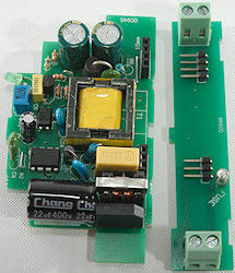
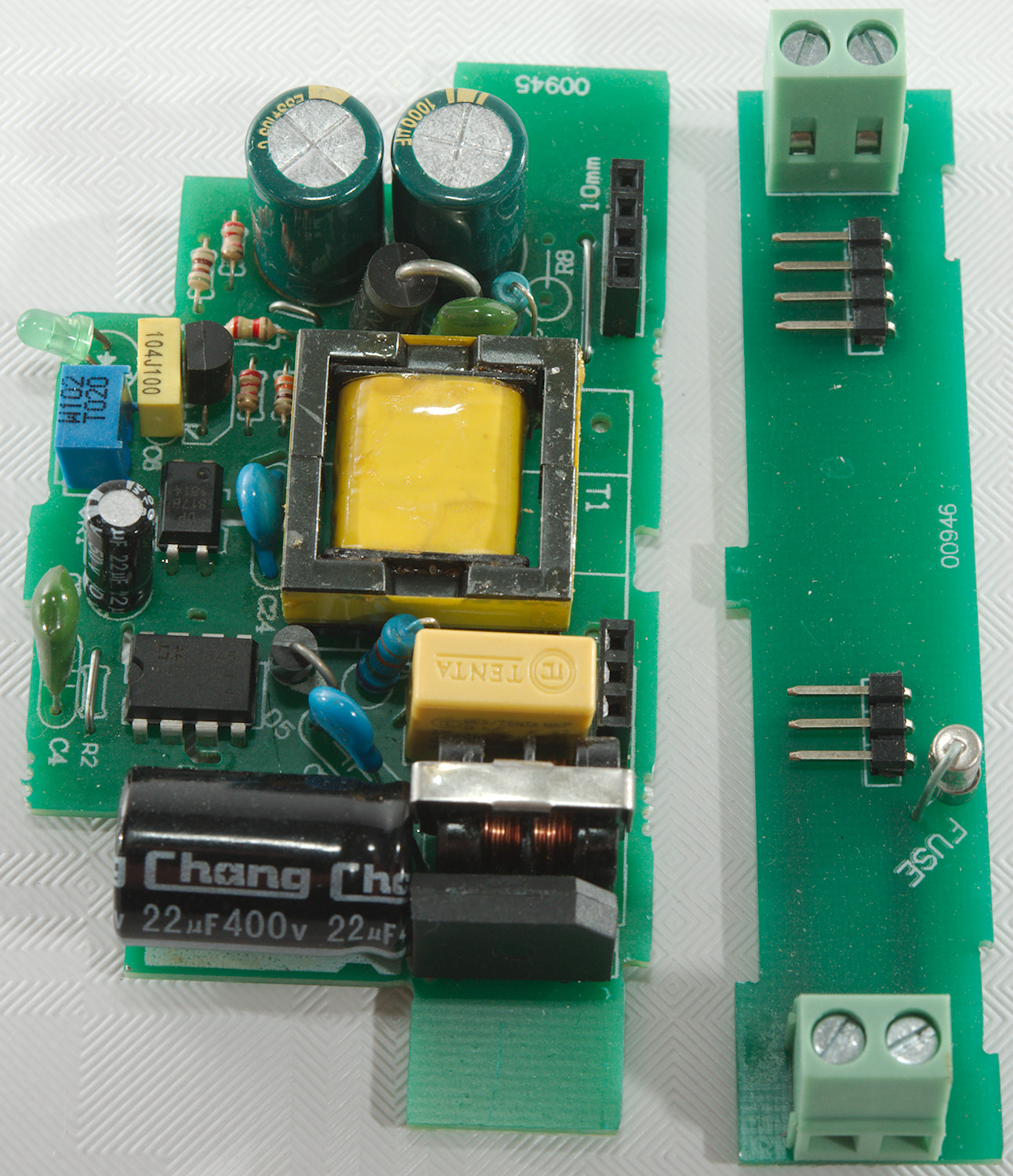
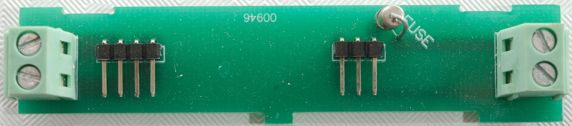
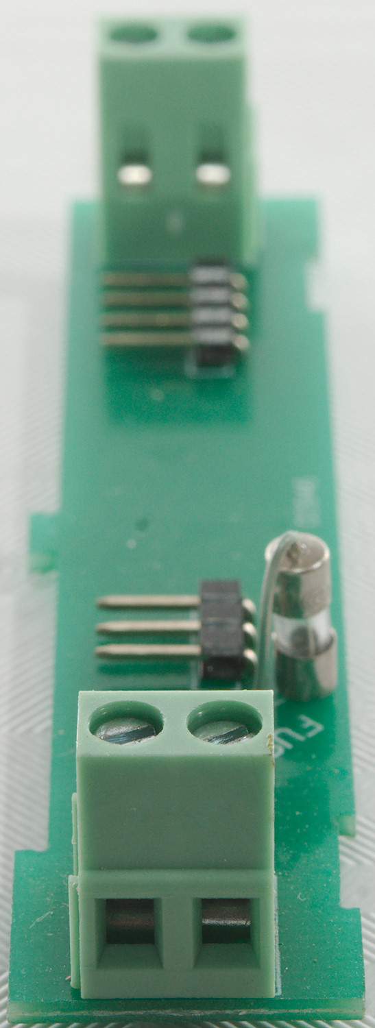
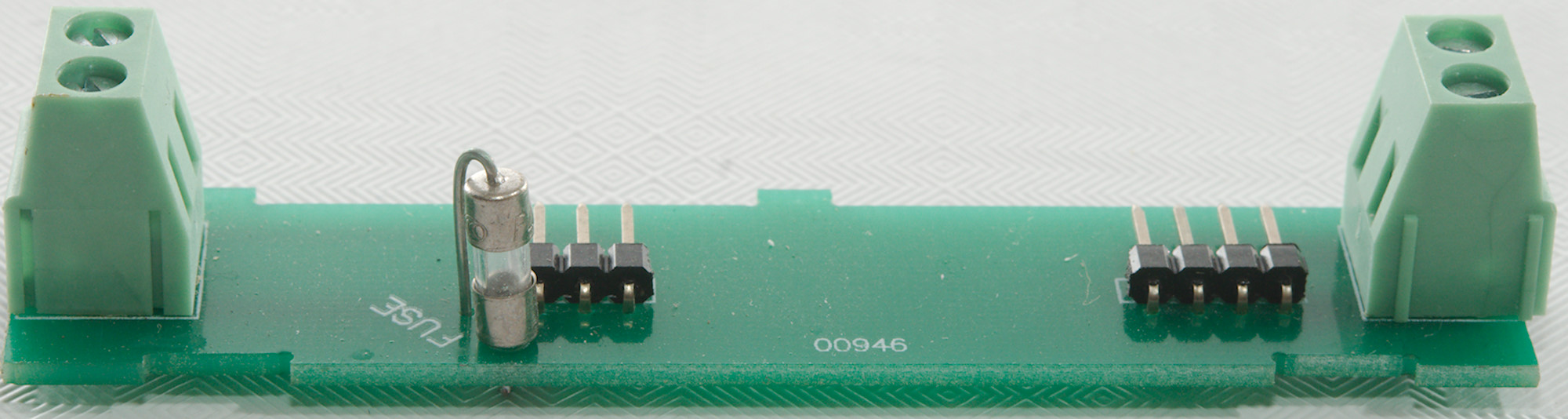
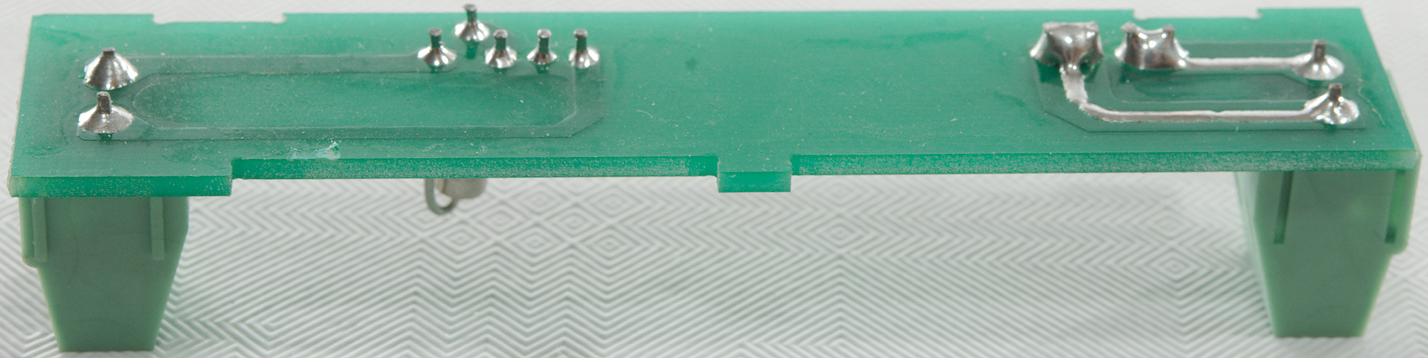
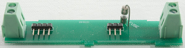
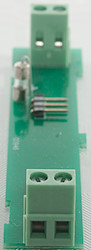
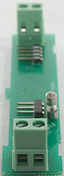
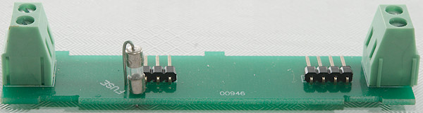
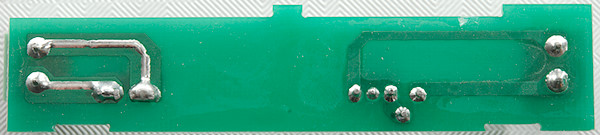
Here I have separated the two boards.
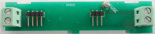
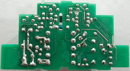
This board contains the terminals and the fuse. The DC side has two connections for each power line, but there is no sense line, I wonder how well that matches with 1% line regulation (Total resistance of connections and tracks must be below 20mOhm for this to be valid). In my test it looked more like 2.8% line regulation.
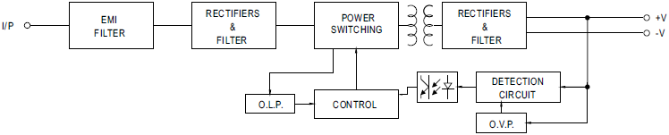
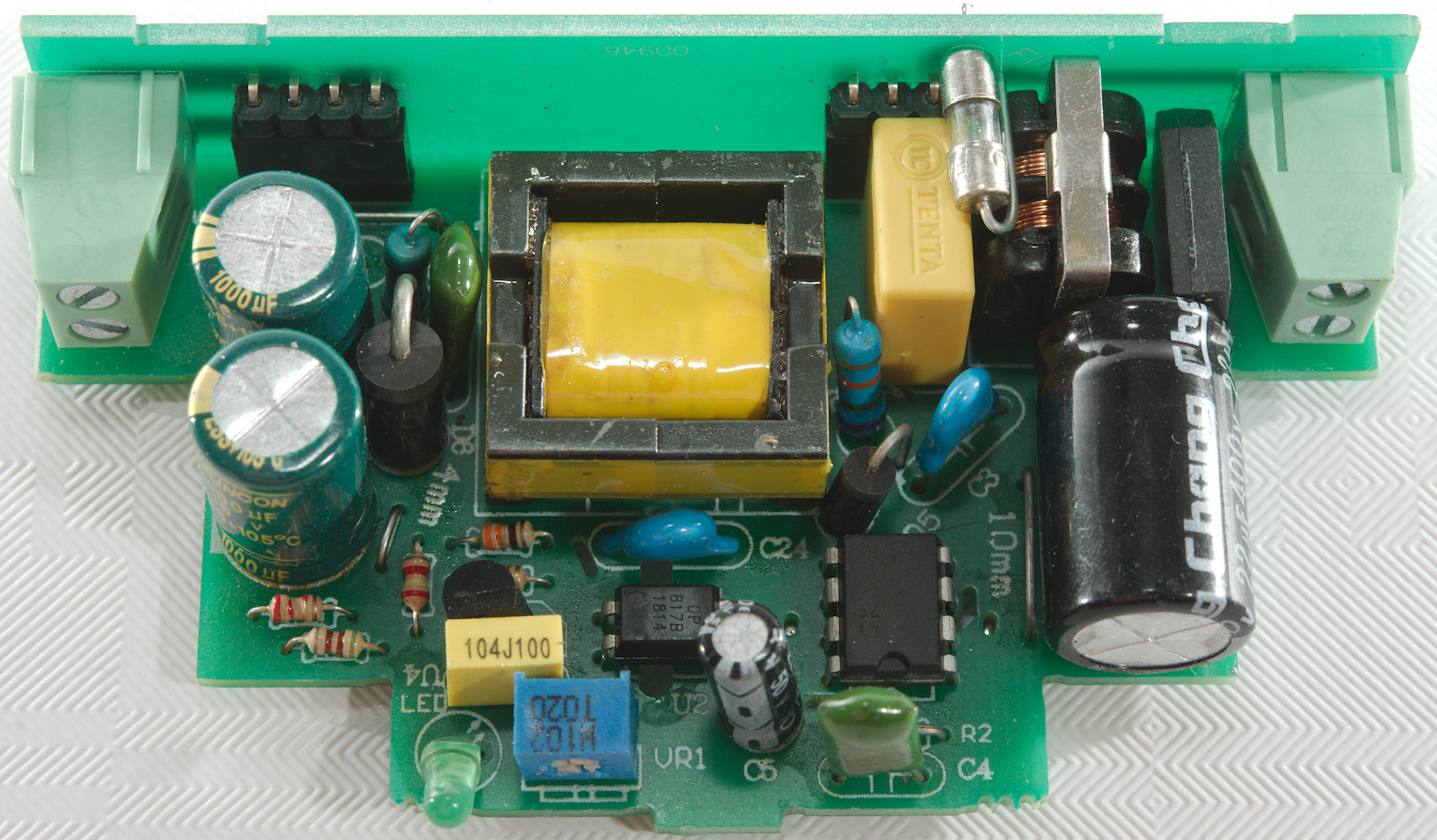
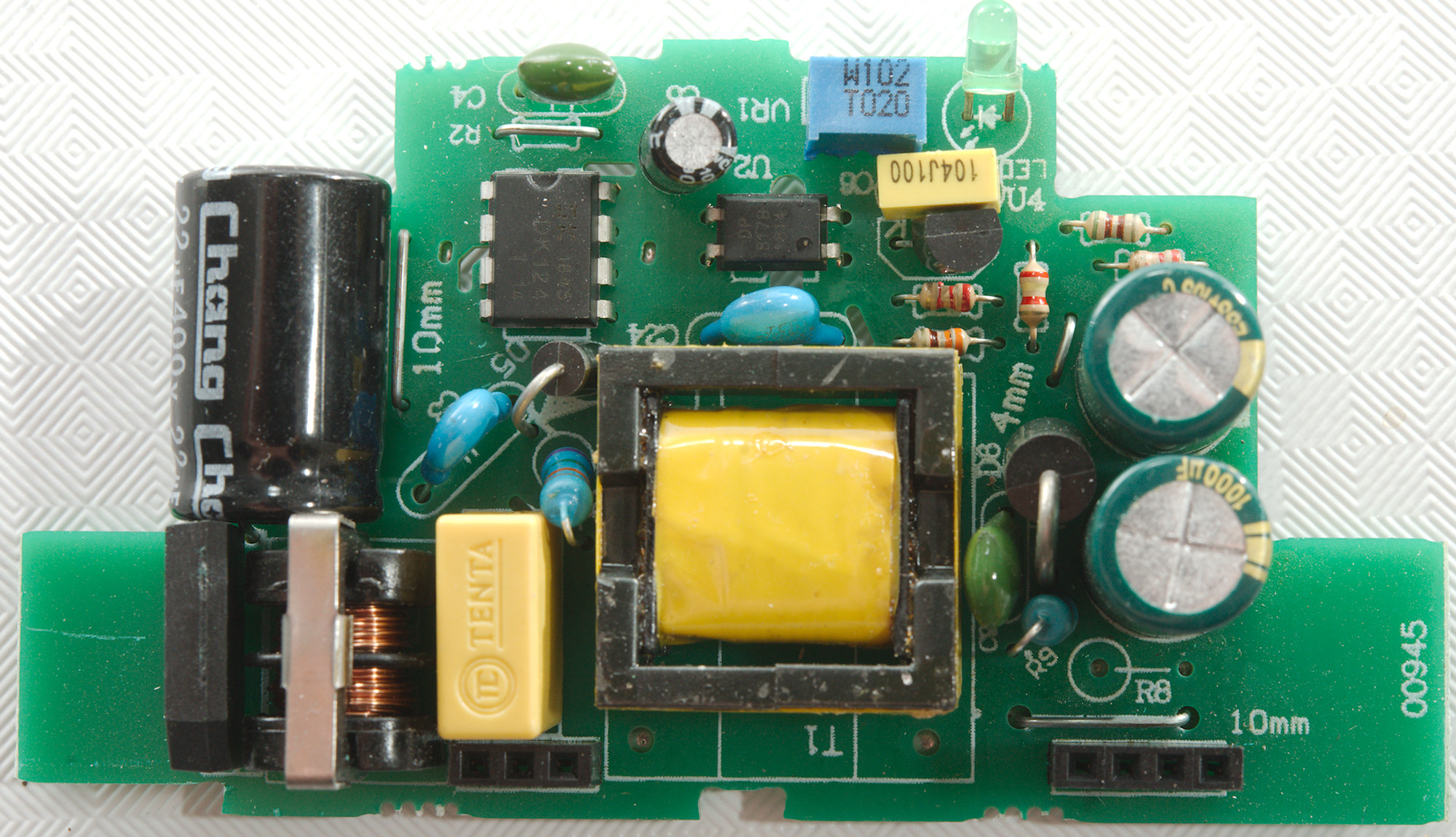
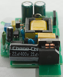
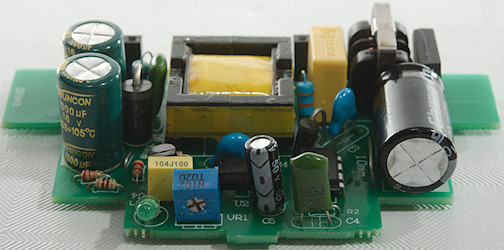
The datasheet contains a block diagram of the circuit, lets see how it matches to the actual circuit. This schematic is very generic and will match just about any power supply with opto feedback, the exceptions are EMI FILTER on input and O.V.P. on output.

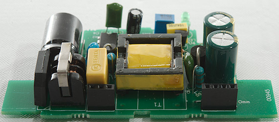
The input have the usual common mode coil (EMI FILTER), then a rectifier and capacitor (RECTIFIERS & FILTER), then the switcher IC (DK124: 12W ~ 18W) (POWER SWITCHING, O.L.P, CONTROL). Between mains and low volt side is a safety capacitor (C24) and opto coupler (U2). On the low volt side the a large rectifier diode (D6) with a RC filter (R9 & C9) across and two smoothing capacitors (RECTIFIERS & FILTER). There is the usual reference (U4: TL431) with support resistors (DETECTION CIRCUIT). I do not see any extra over voltage protection (O.V.P.).
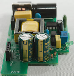
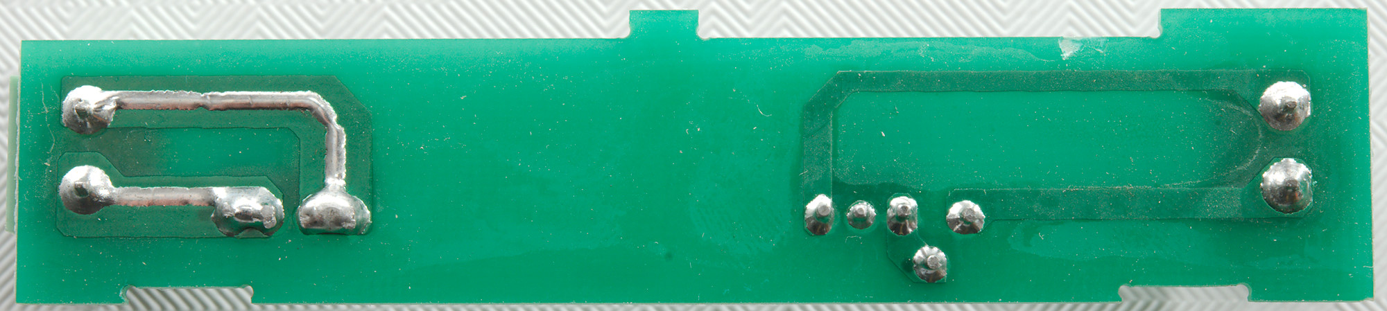
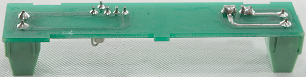
The circuit layout is a bit interesting, the output capacitors are on a branch, not the main current path and only one of the outputs has a sense wire, the other has a long thin connection from the sense to the output.
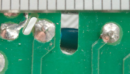
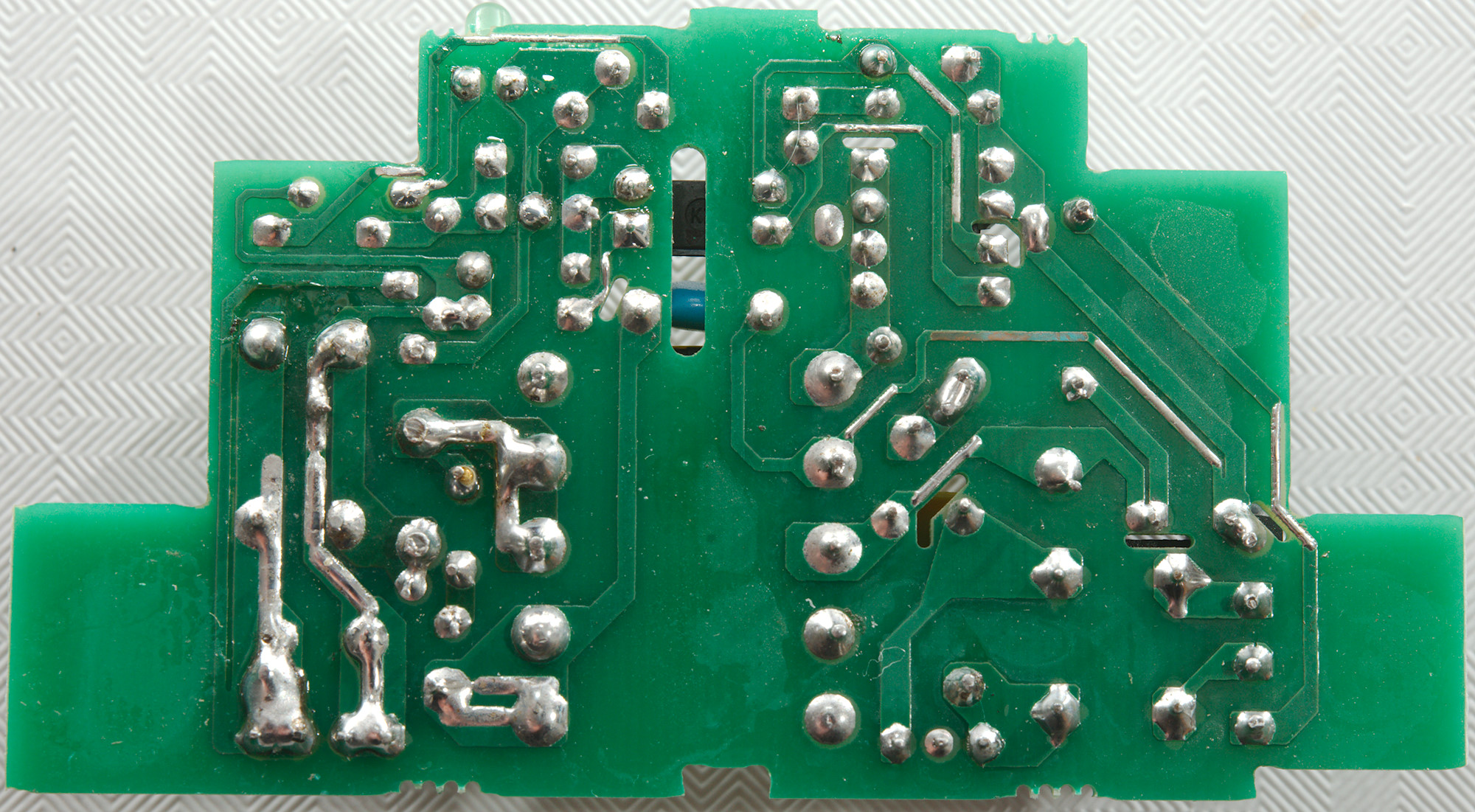
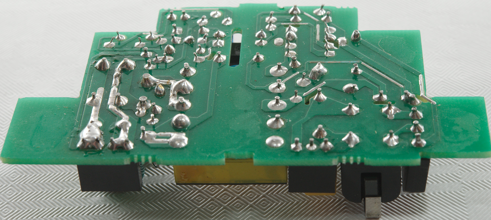
Distance between mains and low volt side is 4mm at the slot and 5.5mm after the slot.
Testing with 2830 volt and 4242 volt between mains and low volt side, did not show any safety problems.
Conclusion
This power supply works fairly well, but has a fairly high noise level, I doubt it is from MeanWell. I would also have expected a brand name on the circuit board and a UL mark.
I will not recommend using it at full power, doing that will mean a short lifetime for the supply.
Notes
The power supply was supplied by a reader for review.
Index of all tested USB power supplies/chargers
Read more about how I test USB power supplies/charger
How does a usb charger work?