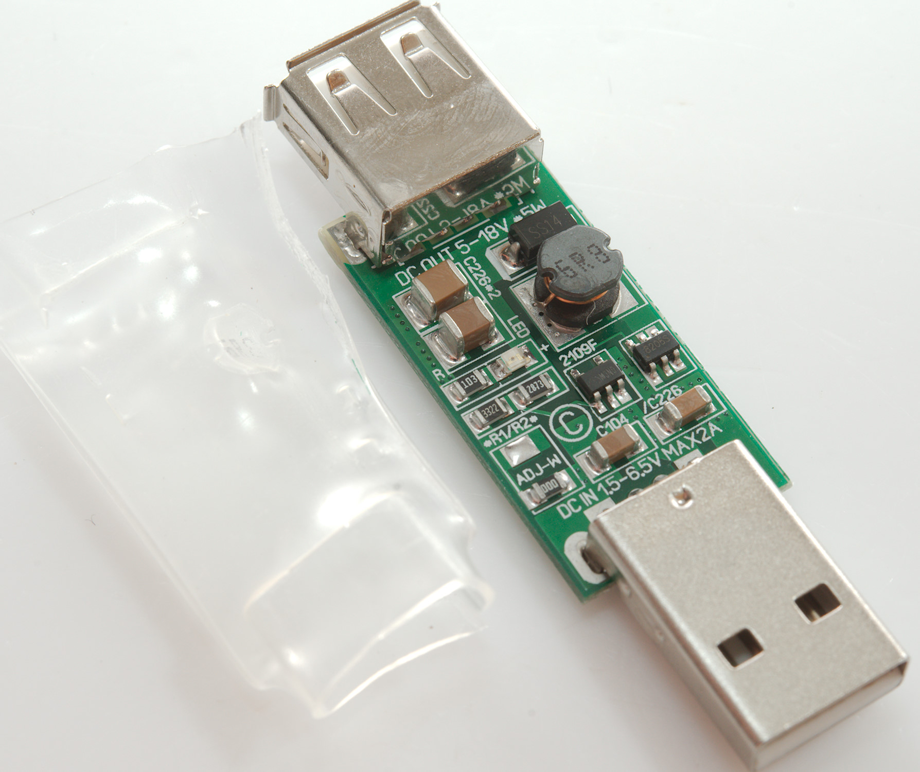
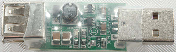
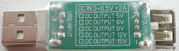
USB 5V to 12V module with heatshrink
Official specifications:
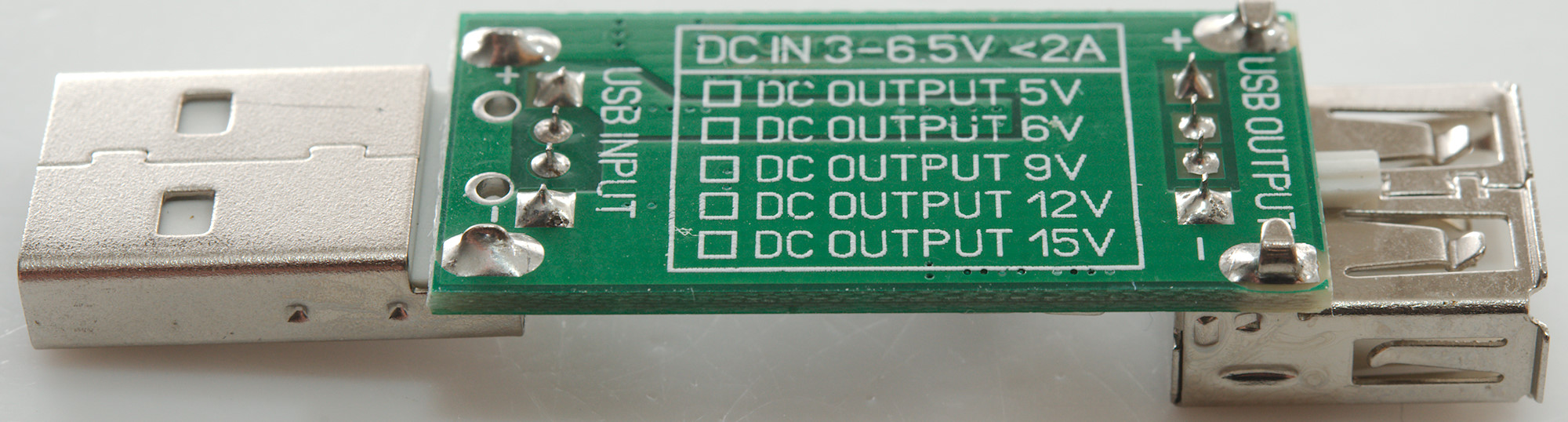
- USB Input DC 3-6V,Maximum 6.5V
- USB Output DC 12V+-5%;
- maximum load: 8W (Recommended <= 5W)
- Size : 34*16mm (Does not include USB interface)
I got it from ebay dealer: canton-electronic
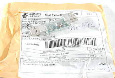
It arrived in a envelope.
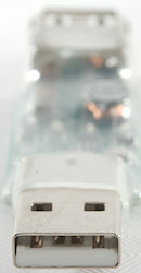
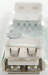
It uses USB for for 5V input, but also USB for 12V output, this will be deadly to many USB devices.
Measurements
- Power consumption when idle is 3mA from 5V
- Weight: 6.8g
- Length: 57.5 x 17.4 10.3mm included heat shrink and USB connectors (PCB is 34mm long)
During my test I used a 3A input current limit and did not try to draw more than 660mA on the output.
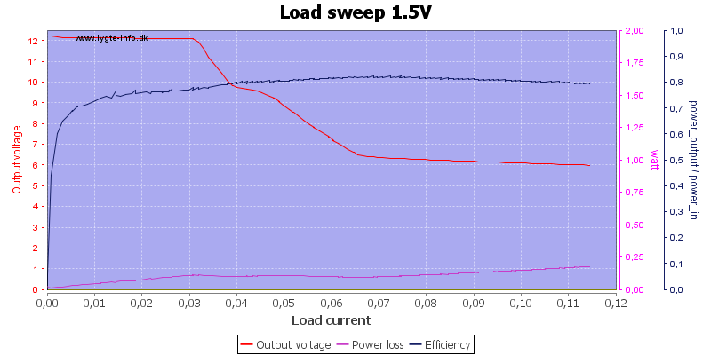
The circuit board specify that it works from 1.5V, that is correct, but it can only deliver 30mA.
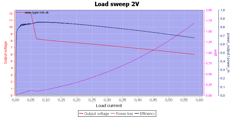
At 2V input it is slightly better with 50mA output current.
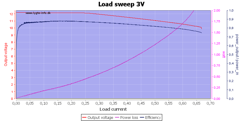
At 3V input it is more useful with 250mA output current.
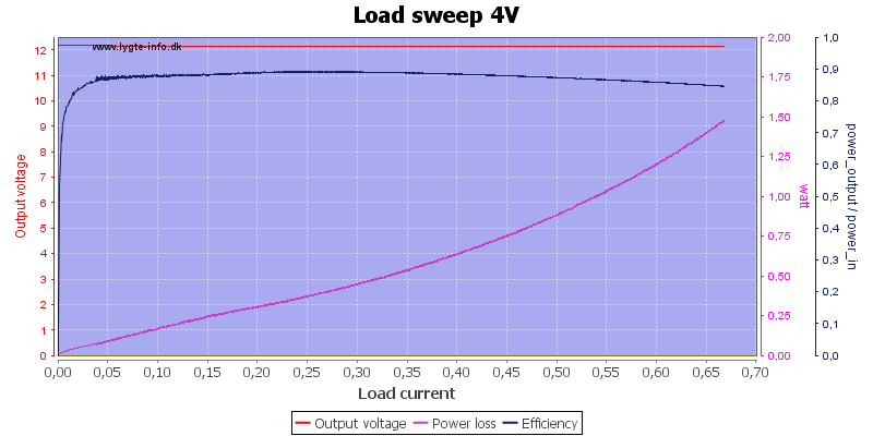
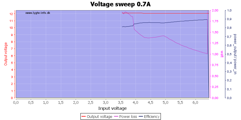
With 4V input it can deliver more than 650mA, but with a fairly high loos in the circuit.

At 5V the output is also more than 650mA and the loss is smaller.
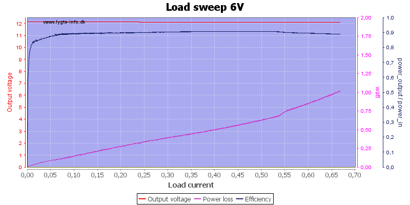
Increasing the input voltage to 6V the loss is again lower.
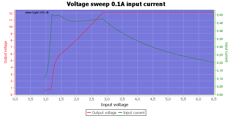

With 100mA output it can be used from around 3V input voltage.
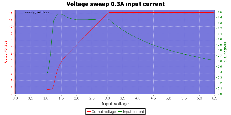
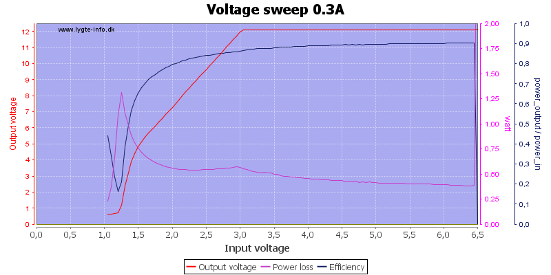
With 300mA output the voltage must be slightly above 3V
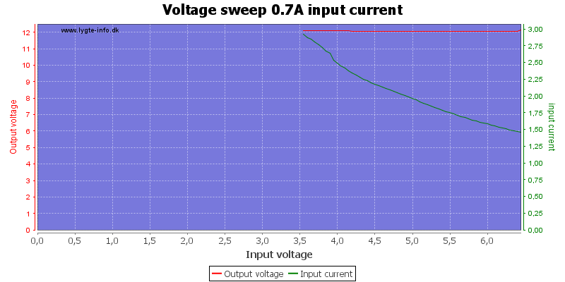
At 0.7A I stopped testing when input current reached 3A at about 3.5V input.
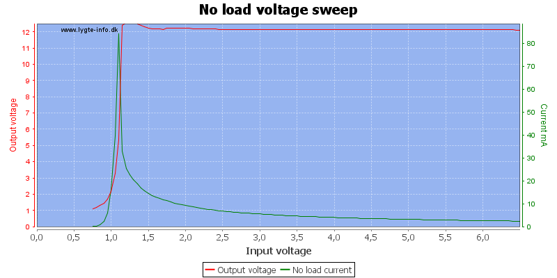
The current consumption is depend on input voltage, but stays at a few mA until voltage gets down to around 2V
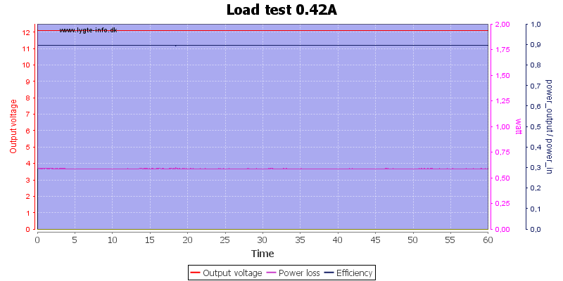
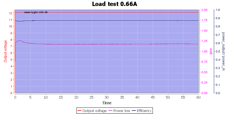
It worked fine with 420mA for one hour.
The temperature photos below are taken between 30 minutes and 60 minutes into the one hour test.
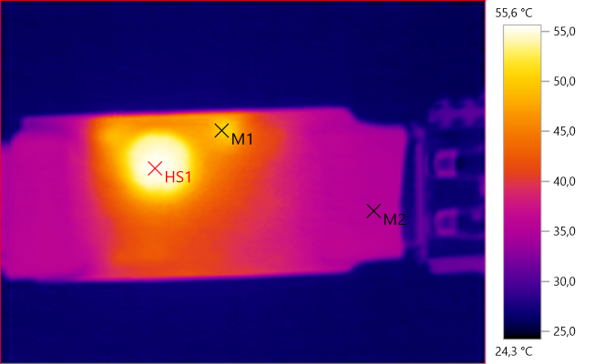
M1: 50.2°C, M2: 35.4°C, HS1: 55.6°C
The hot part is the inductor.
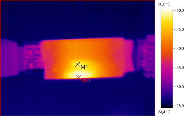
M1: 48.1°C, HS1: 50.6°C
I tried increasing the power to 8W, i.e. 660mA output, it got considerable warmer, but nothing serious.
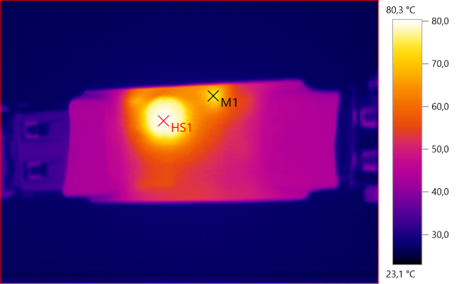
M1: 73.5°C, HS1: 80.3°C
HS1: 70.3°C
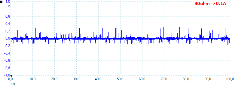
Noise with 5V input and 0.1A output is 37mV rms and 653mVpp
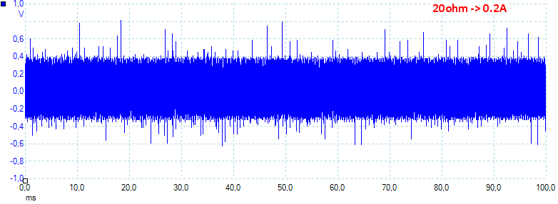
Noise with 5V input and 0.2A output is 240mV rms and 1541mVpp, this is a lot of noise, this module needs some external decoupling capacitors.
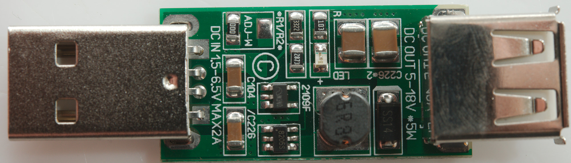
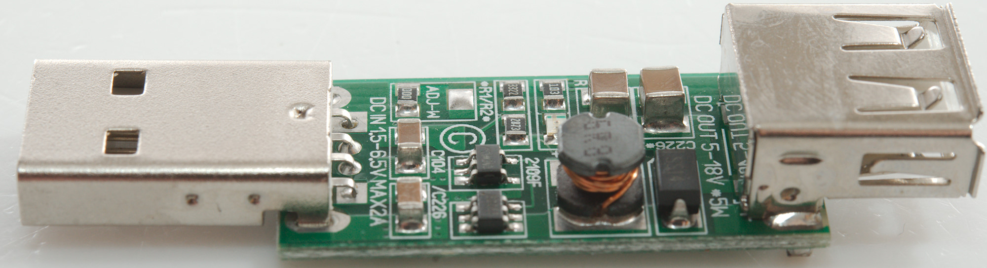
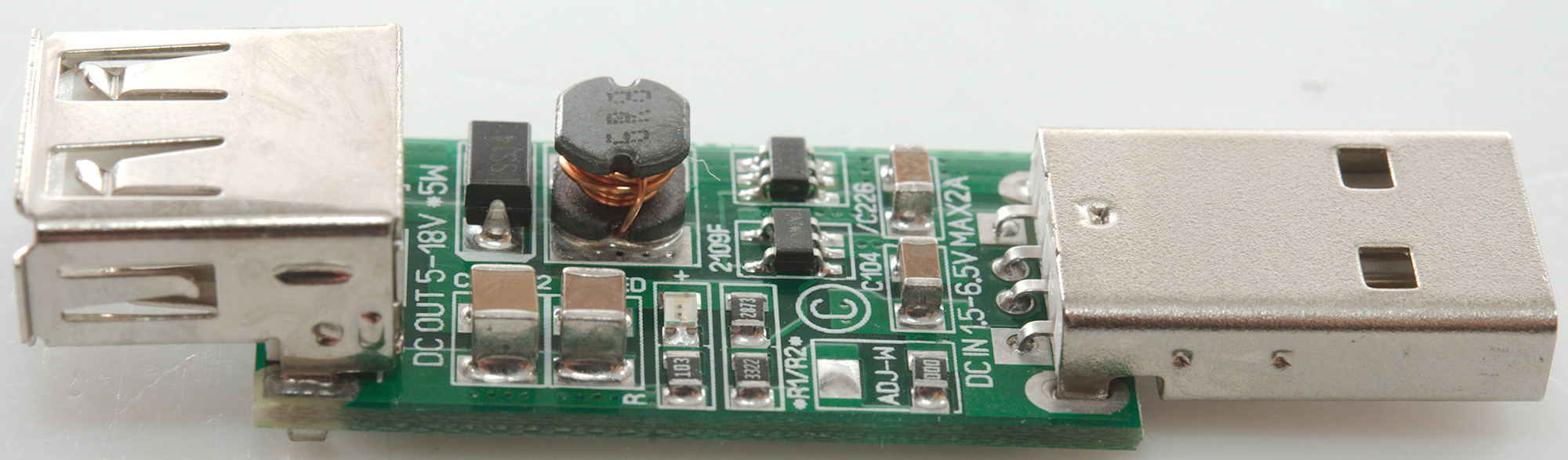
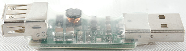
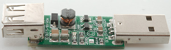
Tear down
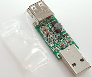
Doing a tear-down on this device is easy, just cut the shrink wrap.
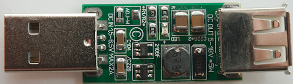
There is some ceramic capacitors at the input, followed by a switcher controller (Marked M3ND and 2109F on circuit board) and a MOSFET (8205S). Then a inductor with a rectifier diode and some ceramic capacitors.
It looks like ADJ-W is used to code the output voltage, here with a fixed 0ohm resistor, but could also have been a trimpot.
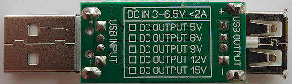
Nice space to mark output voltage, but it is not used.


Conclusion
This is a simple switcher with a fairly old style switching regulators that needs external transistor and diode. The final result has fairly high noise on the output, an external capacitor will probably fix that. The input current can be rather high.
I do not like that the output is a USB connector.
It is usable for small 12V loads and it do not get too hot at the maximum output power.
Notes
Read more about how I test USB power supplies/charger
Compare car chargers and other DC supplied chargers