Tomo Power bank M4
Official specifications:
- Input: 5V / 1.2A
- Output: 5V / 1A, 2A
- 2-in-1: 18650 Battery Charger + Smart Power Bank
- Compatible Battery: 4 x 18650 battery (Not included)
- Weight: 86g
- Size: 10.00 x 8.40 x 2.70 cm / 3.94 x 3.31 x 1.06 inches
I got it from Gearbest
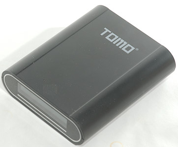
How does it look
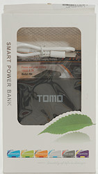

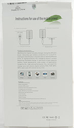

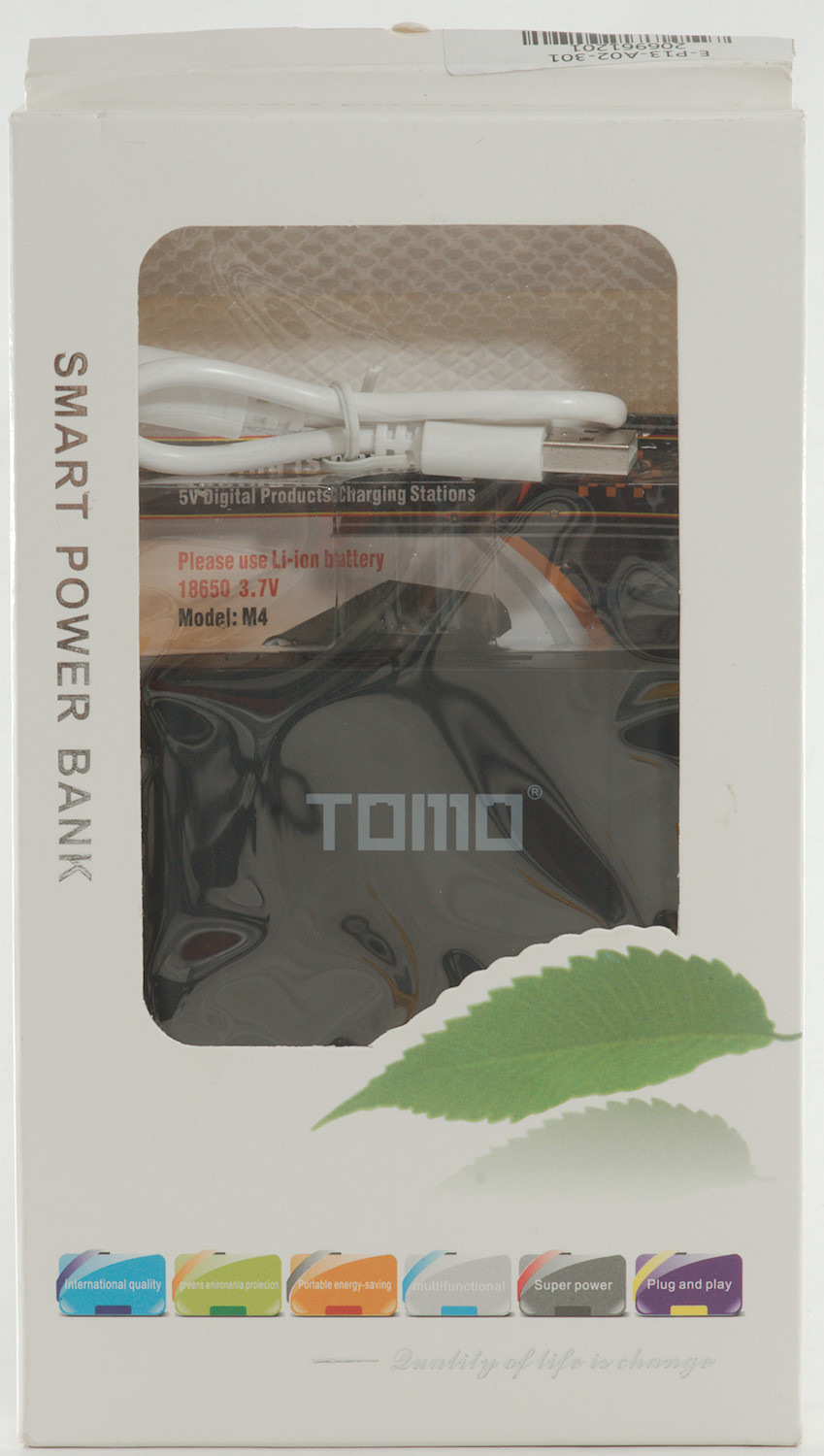
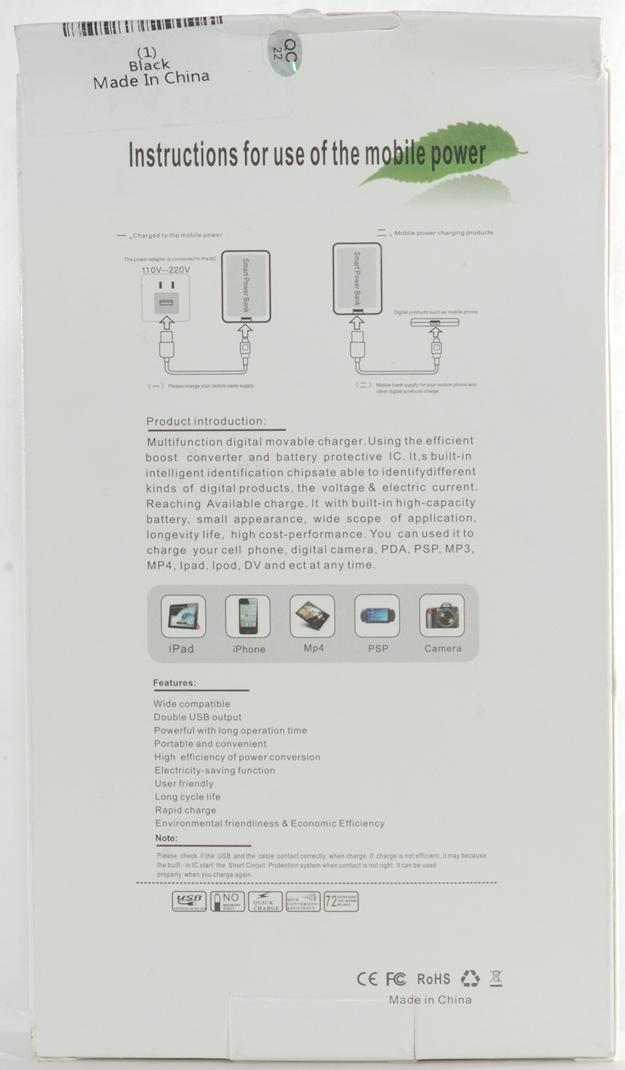
The power bank is delivered in a cardboard box with a window and some specifications on the back.
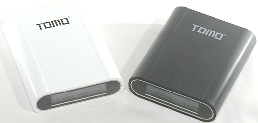
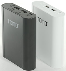
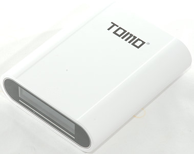
It exist in black and in white.
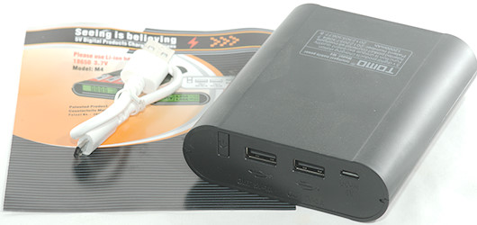
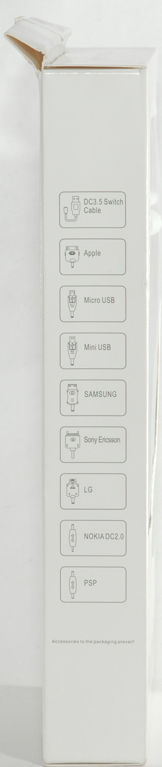
It contains the power bank, a usb cable and a "instruction sheet".
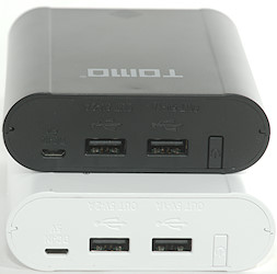
All connectors is placed at one end
- Micro usb: Charge input.
- 1A and 2A usb output.
- Power on button.
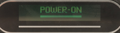
On the other end of the box is a display.
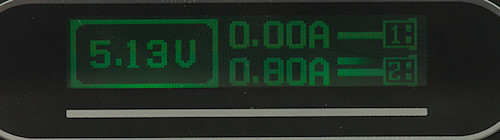
When current is drawn the display will show voltage and current for each slot. The display will not indicate charging.
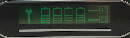
When charging a mains cord is shown to the left and the bars in the batteries are animated.
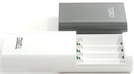
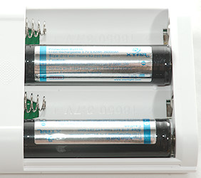
The box do not include any batteries, it is up to the user to supply them.
The length of the batteries can be from about 58mm to 69mm.
Measurements
- Usb output 1A is coded as usb charger (DCP)
- Usb output 2A is coded as Apple 2.1A
- Power consumption from battery when off is 3.5mA
- Power consumption from battery when on is 21mA
- Power consumption from battery at 1.9V is 1.5mA
- Limit for detecting current draw or not is about 65mA load on 2A usb and 65mA on 1A usb output.
- The four battery slots are independent, i.e. no problem mixing full and empty batteries.
- It is possible to use both outputs simultaneous, but the total current is only 2A, this is enforced.
- Can be used as UPS
- Size: 100 x 83.6 x 26.4mm
- Weight: 87.7g (Accessories and batteries not included)
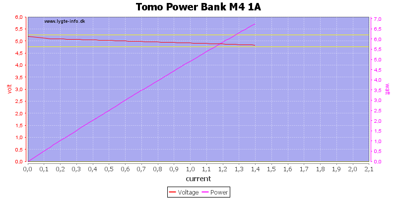
The 1A output can deliver nearly 1.4A before shutting down.
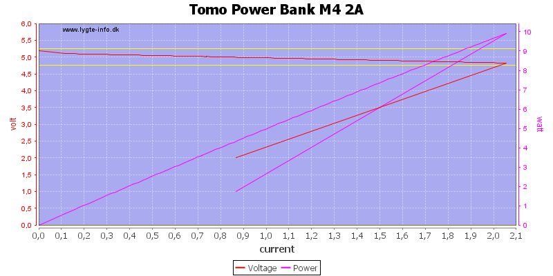
The 2A output can deliver 2A, but not the coded 2.1A
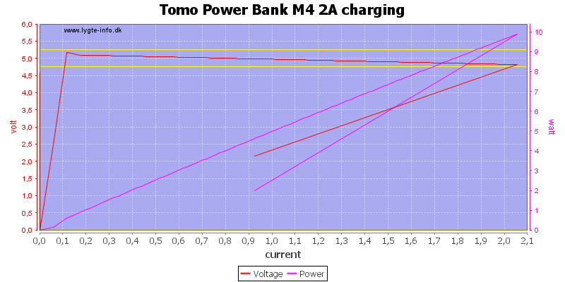
The current limit is not changed when charging.
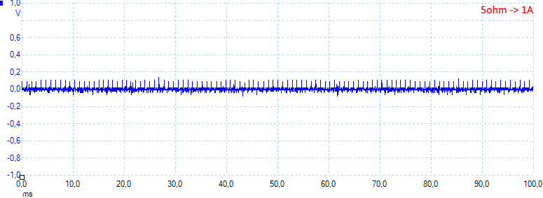
At 0.5A load on the 1A output with a single cell in the power bank the curve looks fine.

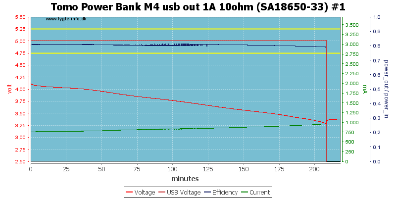
Same with a 1A load.
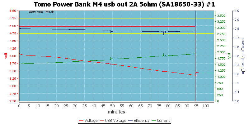
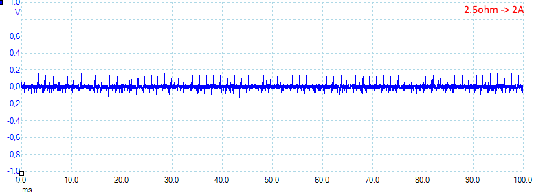
The 2A output with a 1A load from a single cell.
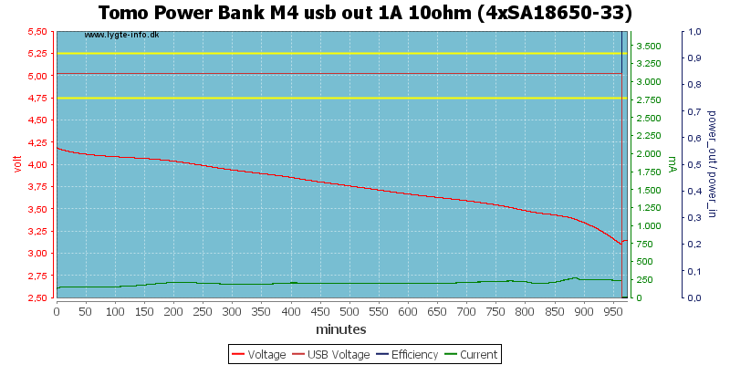
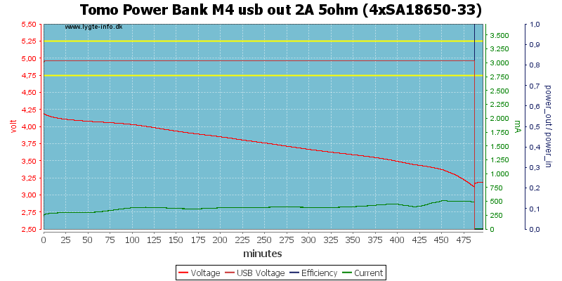
With 4 cell the runtime is more than 4 times longer, here at 0.5A load.
Note: Current measurement is only for one cell.
And at 1A load.
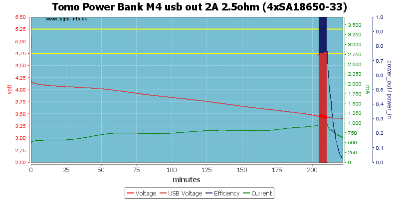
At 2A load the boost converter has trouble when the batteries are about empty. This killed the power bank.
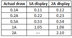
The current display is not a precision meter, but it will easily show if the connected device is charging and give a very good idea on how fast charging is.
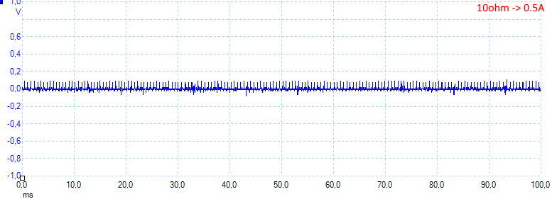
Noise is 16mV rms and 159mVpp
Noise is 24mV rms and 227mVpp
Noise is 26mV rms and 335mVpp, all noise values are fairly very low.
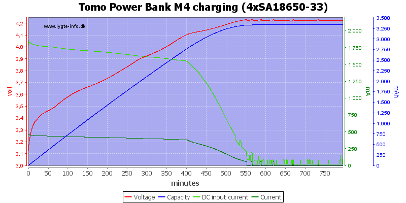
Charging is with a CC/CV voltage charge curve.
Note: Current measurement is only for one cell.
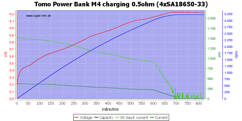
A 0.5ohm in series with the power supply to simulate a long cable or weak power supply will slow down the charging, but not that much.
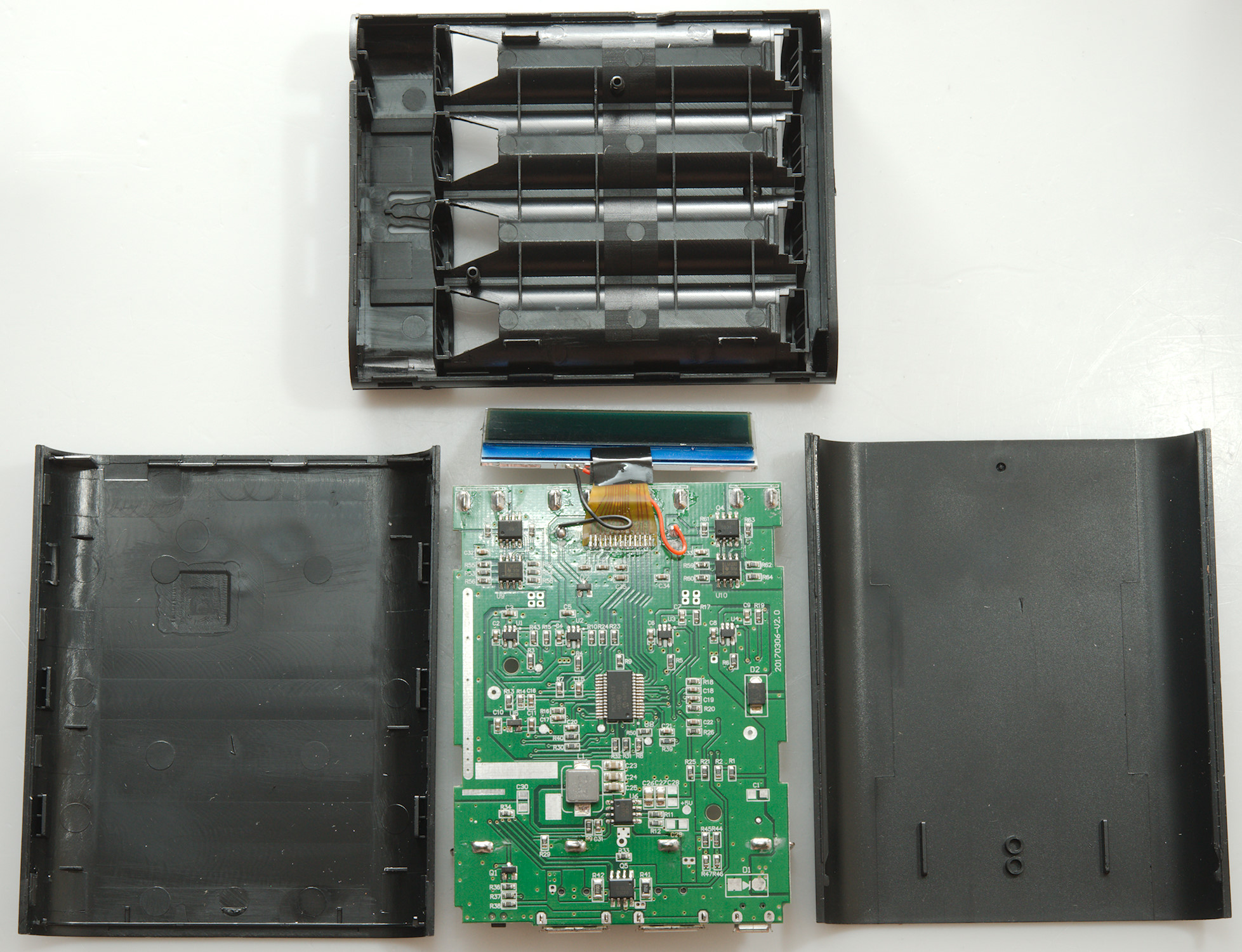
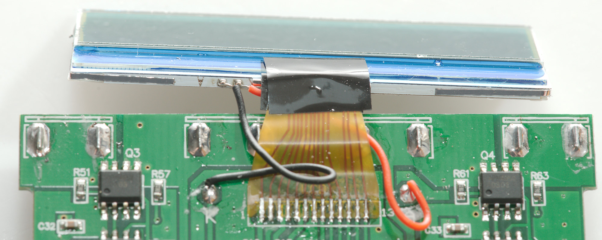
Tear down
With the power bank dead I decided to take a look inside.
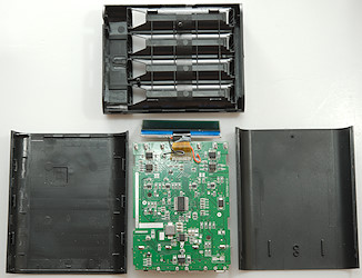
The box was clipped together and could be opened without too much trouble.
There is a lot of electronic inside, lets take a closer look at it.
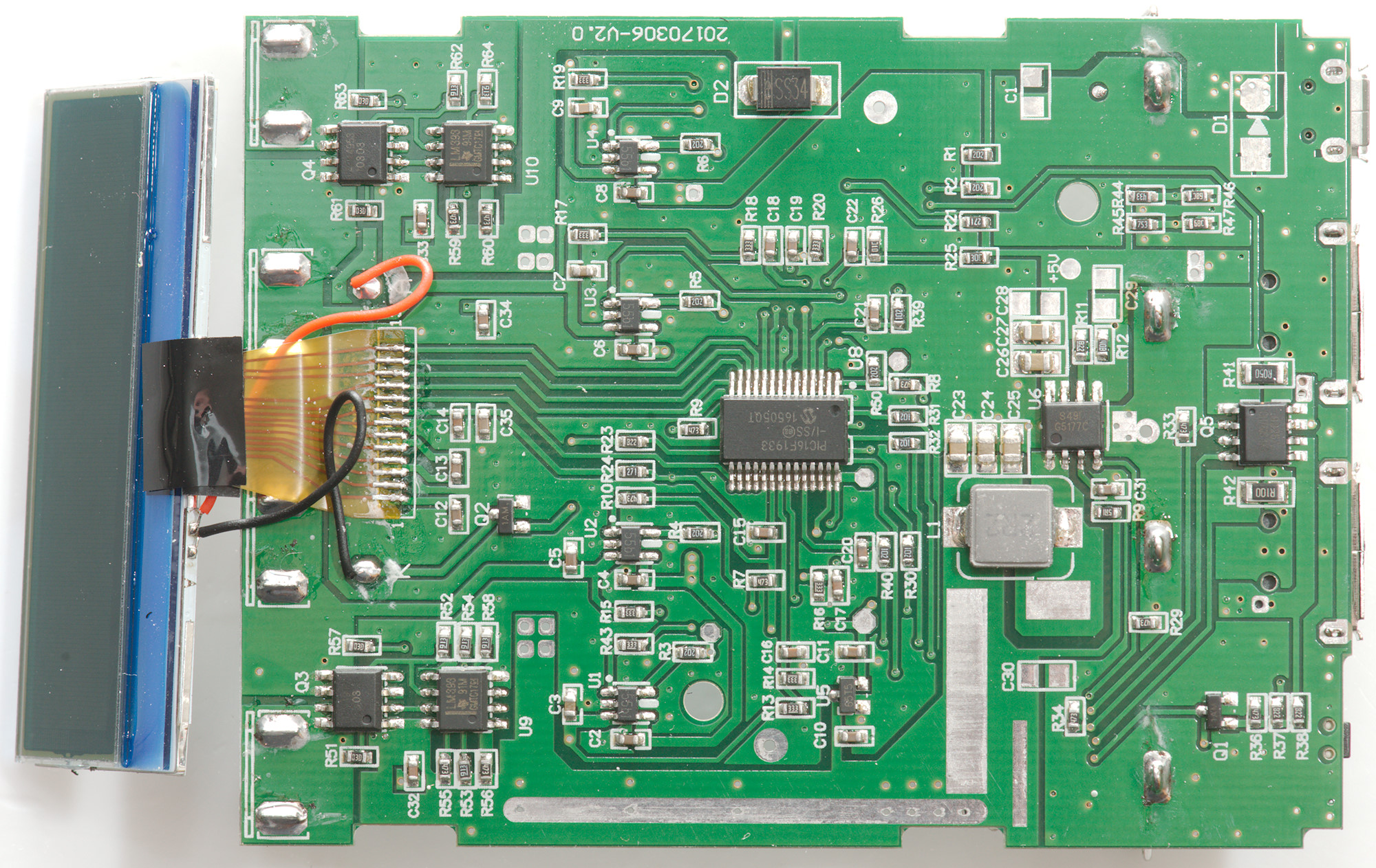
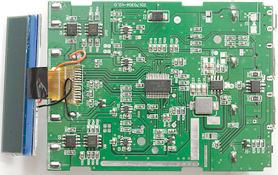
On each side of the display is a dual mosfet (Q3 & Q4) together with dual comparators (U9 & U10: LM393), this is the circuit that is used to select what battery that has to deliver power onto the internal power bus. This power bus can also get power from the usb input via a diode (D2), i.e. if the usb input voltage is a diode drop higher than battery voltage it will supply the boost converter.
Close to the display flat cable connection is a transistor (Q2) to control the backlight .
There is four linear charge ic's (U1, U2, U3, U4), one for each battery.
In the center of the board is the microcontroller (U8:PIC16F1933), it has build-in LCD controller, ADC and lot of other stuff. The display must have a build in controller, the controller in the mcu is too small for this display.
The boost converter is one IC with rectification build in (U6: G5177C) and a inductor (L1).
Near the usb connectors is a dual transistor (Q5) to shut down the outputs and two resistors for current measurements (R41 0.05ohm & R42 0.1ohm). It looks like the ADC (Inside the microcontroller) has lowest range at 1V and I cannot see any amplification, this means the current measurement is only using 10% of the ADC range.
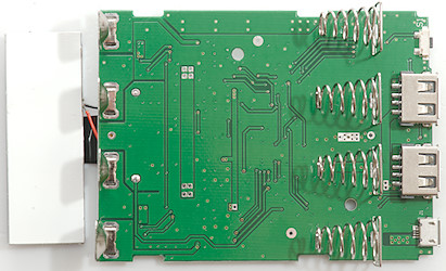
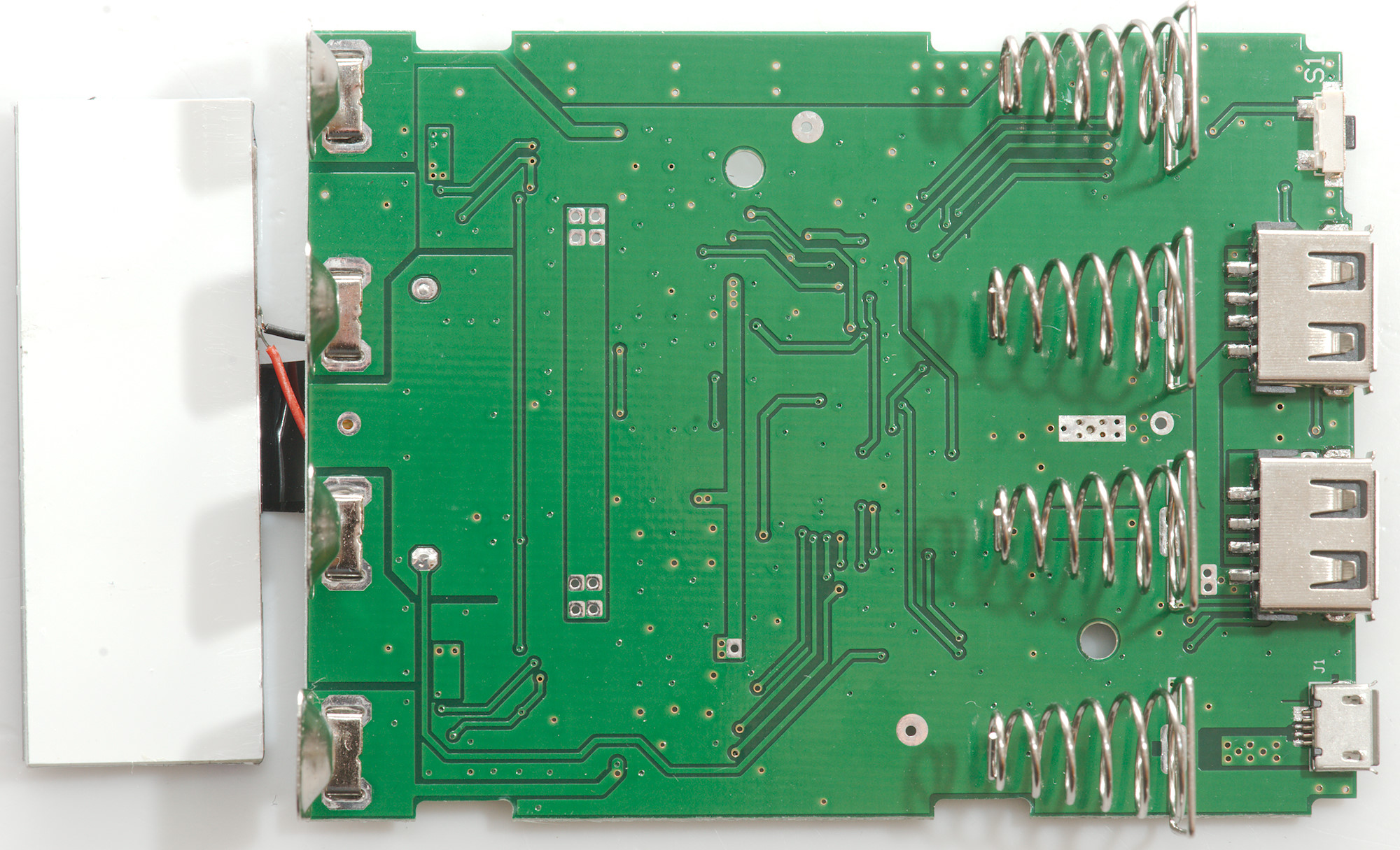
Only usb connectors, switch and battery connections on this side of the circuit board.
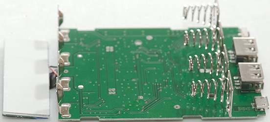


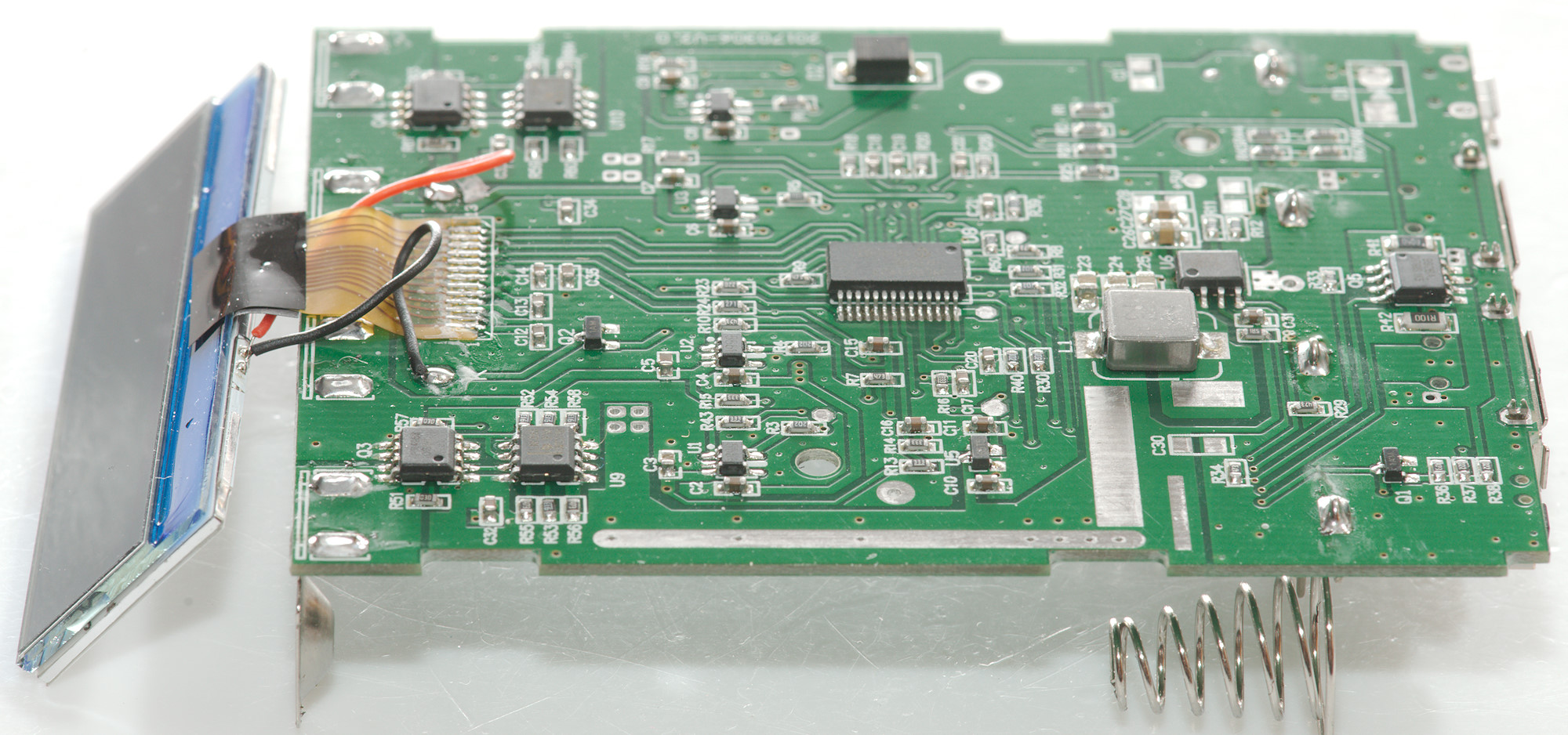
The LCD is controlled directly from the microprocessor, the red and black wires are used for a backlight module mounted on the back of the display.
Conclusion
This power bank has many good details:
- Long battery slot, i.e. can handle some protected batteries.
- Can be used as UPS
- Independent slots
- The display with current for each port
- Overload protection
- Easy battery replacement, this makes it possible carry spare batteries or use it as 18650 charger.
But the standby current is a bit on the high side, i.e. the batteries has to be charged every few months even when not using it. I would also have like a bit more current on the 2A port and auto coding.
It looks like this type of power bank has problems with delivering full power for long time: they die.
I will rate it as acceptable.
Notes
The power bank was supplied by Gearbest for a review.
Read more about how I test USB power supplies and chargers