Baseus Speed PPS Quick Charger USB+Type C 30W BS-EU905
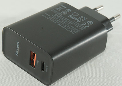
Official specifications:
- Output power 30W
- Input voltage: 100-240V
- Output Type-C: 5V 3A, 9V 3A, 12V 2.5A, 15V 2A, 20V 1.5A
- Output USB-A: 4.5V 5A, 5V 4.5A, 9V 3A, 12V 2.5A
- Total output: 5V 5A max.
- Size: 58 x 52 x 28mm
- Weight: 92g
I got it from Aliexpress: BASEUS Official Store
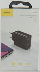

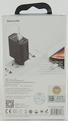

I got the charger in a cardboard box with specifications on.
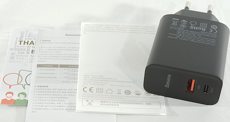
It contained the charger and a instruction sheet.
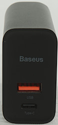
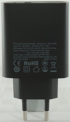
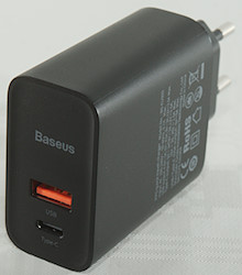
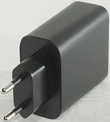
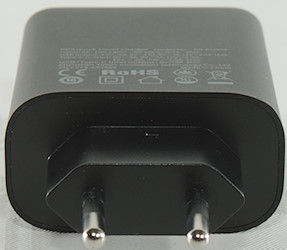
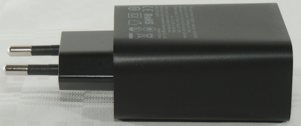
Measurements
- Power consumption when idle is 0.13 Watt
- USB QC and PD shares a converter, i.e. only one output works when using advanced coding (QC, PD, etc.)
- USB QC supports 20V output (This is very uncommon).
- PD output supports 5V 2A, 9V 3A, 12V 2.5A, 15V 2A, 20V 1.5A, PPS3-5V 3A, PPS:3-11V 3A
- PD output can also do DCP, Samsung, Apple 2.4A, QC3 Huawei-FCP, PE2 & Samsung-AFC
- Regular USB output can do Apple 2.4A, Samsung, DCP, QC3, Samsung AFC, Huawei-FCB & SCP
- Minimum QC3 voltage is 3.6V
- Weight 93.3g
- Size: 95.5 x 52.2 x 28.3mm
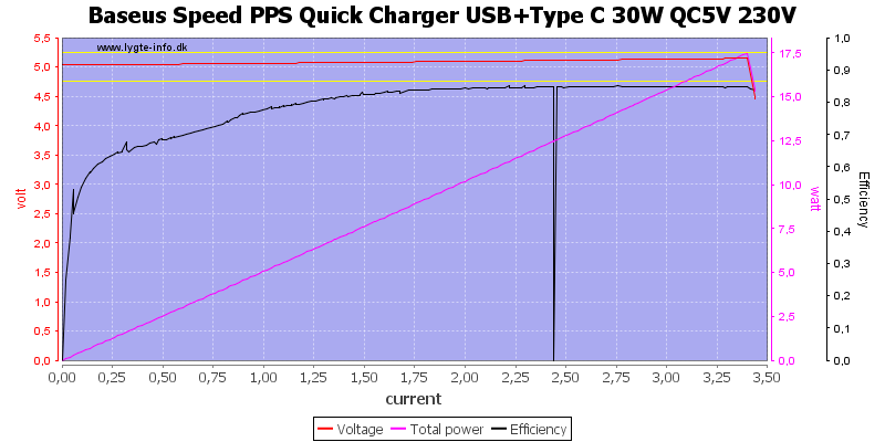
At 5V the output can deliver about 3.4A and there is some cable compensation.
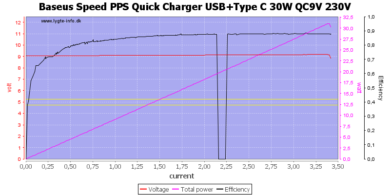
At 9V the limit is the same.
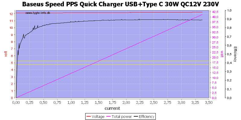
And also at 12V.
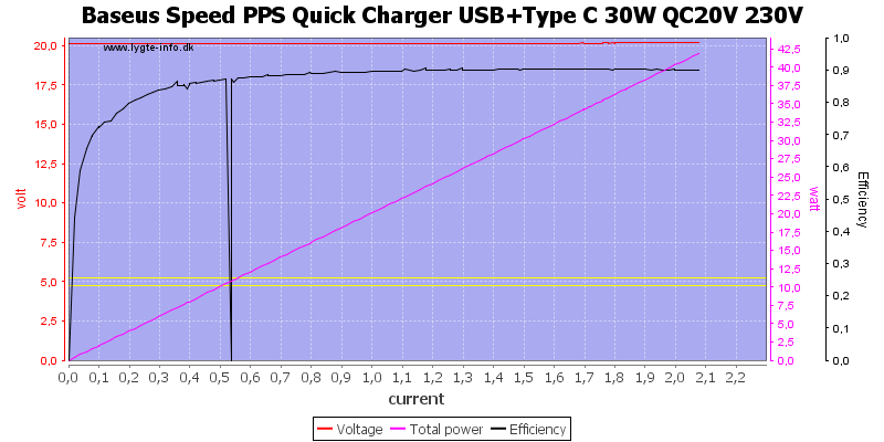
The charger can do QC at 20V, there the current is limited to 2.1A
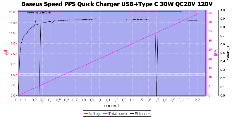
And slightly more at 120VAC.
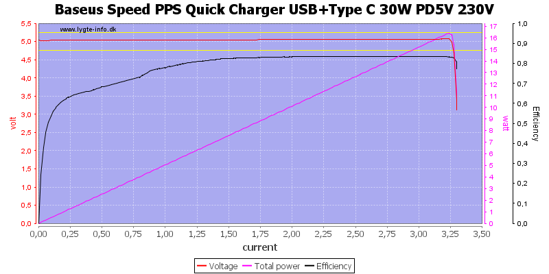
The PD output has exactly the same current limit at 5V.
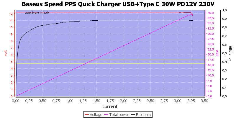
At 12V
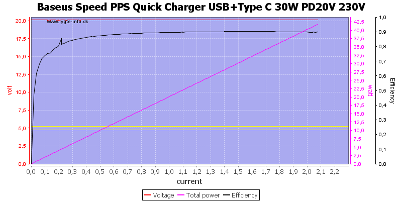
And at 20V
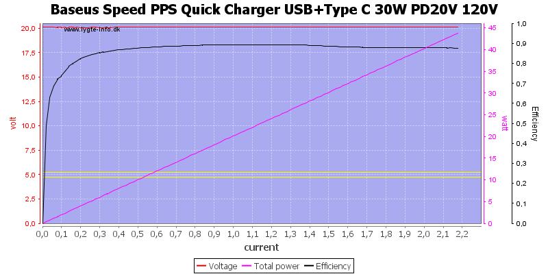
And at 20V with 120VAC.
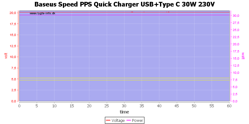
For the load test I used 20V 1.5A, but I could only test on one output.
The temperature photos below are taken between 30 minutes and 60 minutes into the one hour test.
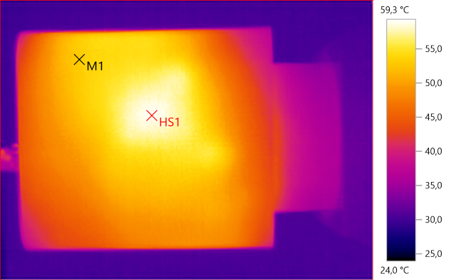
M1: 53.0°C, HS1: 59.3°C
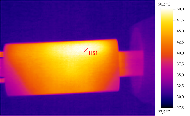
HS1: 50.2°C
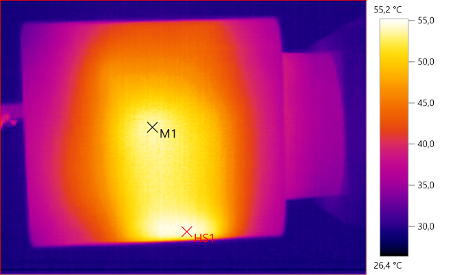
M1: 53.9°C, HS1: 55.2°C
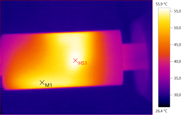
M1: 54.0°C, HS1: 55.9°C
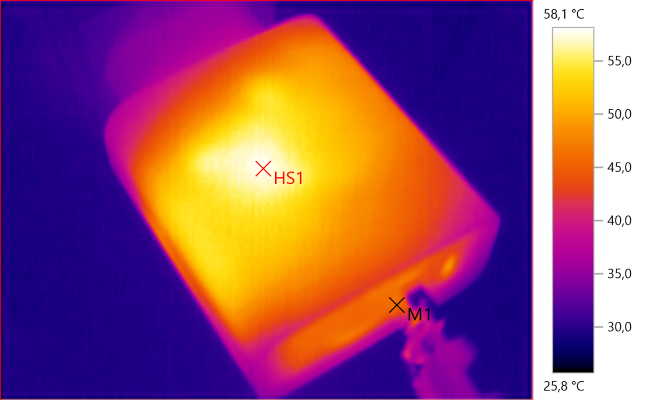
M1: 45.6°C, HS1: 58.1°C

At 0.5A the noise is 10mV rms and 90mVpp.

At 1A the noise is 11mV rms and 88mVpp.

At 2.5A the noise is 27mV rms and 216mVpp.
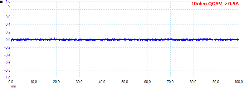
At 9V 0.9A the noise is 13mV rms and 110mVpp.
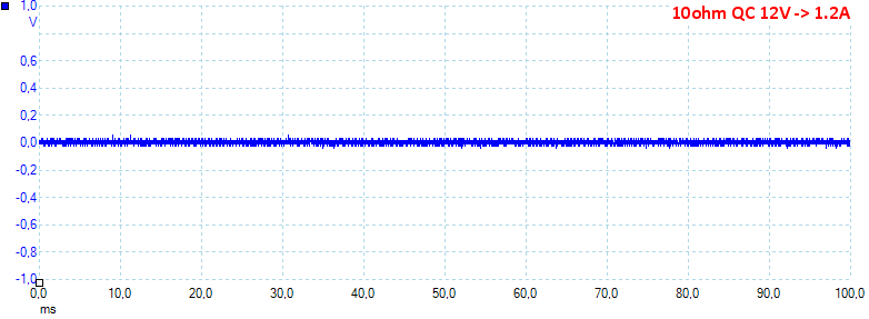
At 12V 1.2A the noise is 18mV rms and 127mVpp.
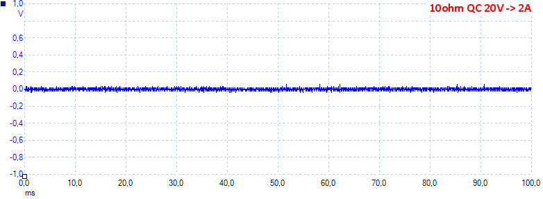
At 20V 2A the noise is 20mV rms and 142mVpp, the noise is very low.
Because QC and PD uses the same converter I did not measure on PD, they will be similar.
Tear down
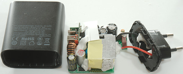
I could open this charger the usually way: Mounting the plug in my vice and banging on the enclosure with my mallet.
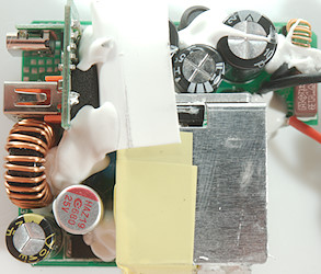
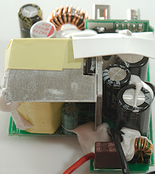
There is a fuse and a common mode coil at the mains input, then 3 smoothing capacitors with a inductor between. The main switcher transistor is mounted on a heatsink that has two layers, one goes on top of the transformer. There is a safety blue capacitor, but it is not easy to see.
The low volt side has a diode (DK5V100R25: Synchronous rectifier) and again 3 smoothing capacitors with a inductor between, this time a rather large inductor due to the high current. The two USB connectors is mounted on a small circuit board or rather two circuits boards.
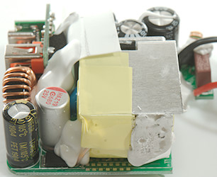
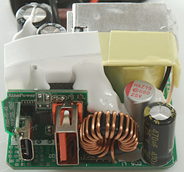
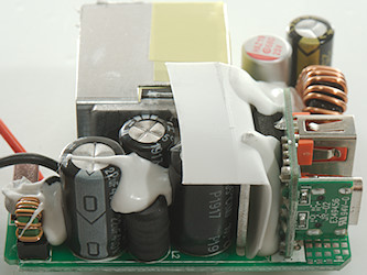
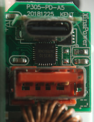
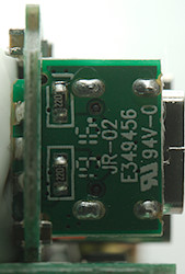
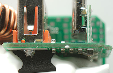
The small circuit board contains a controller chip (SW3510). There are probably also two power mos transistors, I can see one of them below the USB-C connector (RU3040), the other is hidden on the back of the circuit board.
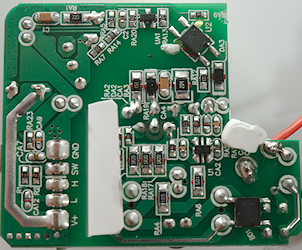
On this side of the circuit board is the bridge rectifier (BD1), the mains switcher (U1: Marked SPt c6). There is also a opto coupler (U2) and a reference (UA1: 431).
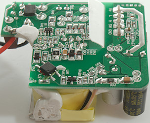
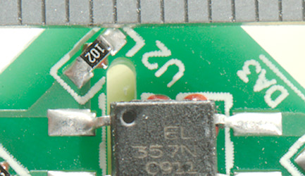
The distance between mains and low volt side is very good.
Testing with 2830 volt and 4242 volt between mains and low volt side, did not show any safety problems.
Conclusion
This charger is for one device at a time and it do that very well with low noise, auto coding, lot of power (But not enough for laptops) and good safety. The two output are not really designed to be used simultaneous except with very simple devices.
Notes
Index of all tested USB power supplies/chargers
Read more about how I test USB power supplies/charger
How does a usb charger work?


