Electronic load DTU-CC01
Official specifications:
- Material: PCB
- Display: 128 * 64
- Input Voltage: 3.6V~30V
- Input Current: 0.2~3A
- Voltage Resolution: 0.001V
- Current Resolution: 0.001A
- Rated Power: 25W
- Max. Power: 35W
- Wire Resistance Measurement: Pressure-drop method
- Input Interface: USB-A, TYPE-C, Micro USB
- Capacity: 0~9999.9AH, 0~9999.9Wh
- Protocol Trigger: for QC2.0, QC3.0, FCP, SCP, AFC
- Working Temperature: 0~70°C
- Item Size: Approx. 11.5 * 4cm / 4.53 * 1.57in
- Item Weight: Approx. 57g / 2.01oz
I bought from Aliexpress dealer: Sun-Shine Home
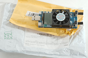
Like many devices from China this arrives in a envelope or in this case two envelops inside each other.
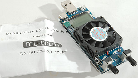
It included the load an a instruction sheet.
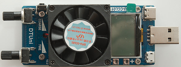
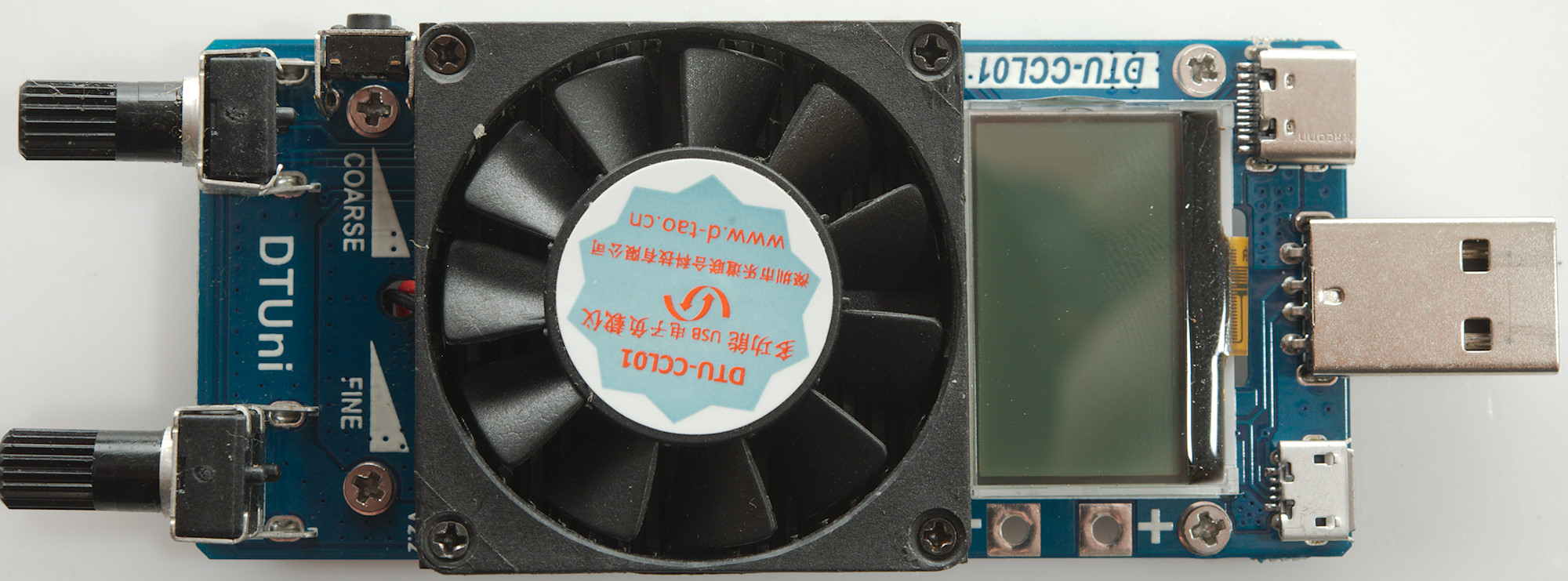
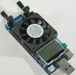
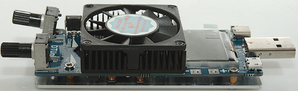
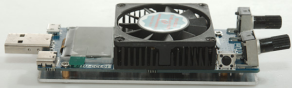
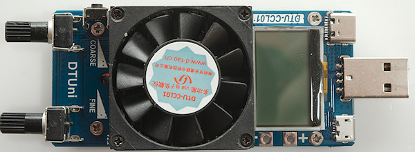
From left to right: The two current adjust potentiometers and the button, heat sink with fan, display and 3 different usb connectors.
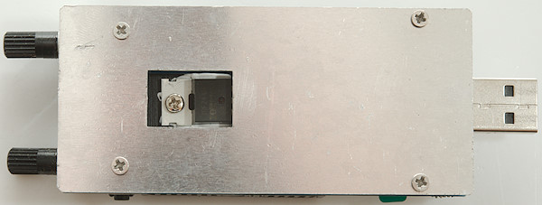
The bottom is an aluminium plate, but it is not used as heat sink and the screws make it a bit hard on a table (Adding some rubber feet would be a good idea).
Display
There is many different screens on the display, I do not show all of them here.
Usual a fast click on the switch will change screen or line and long click will active current line (Activate trigger, function or change value). The user interface is fairly easy to use for a one button interface.
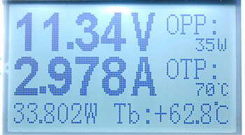
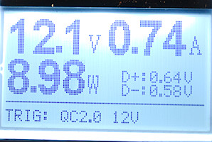
The main screen with actual voltage, current and power. It also shows actual temperature and maximum power and temperature.
Click for next screen or hold down to change maximums.
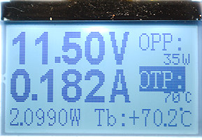
The load got too hot and is cooling down, it cannot turn completely off.
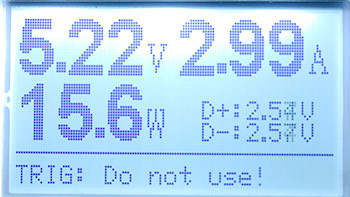
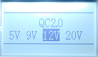
This screen is used for working with fast charge triggers.
Click for next screen or hold down for a list of fast charge schemes.
Here I have used the list of schemes to select and activate a fast charge scheme.
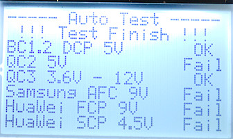
On the list of fast charge schemes one of the points is an automatic test for supported schemes.
This test is not 100% reliable, a charger that supports QC3 will always support QC2 and in the test above I did select QC2 on this charger.
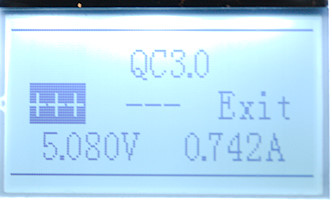
Depending on scheme there is different options to activate them.
Load do not confirm if activating a scheme failed or succeeded, this must be seen on the voltage.
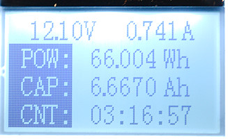
Next screen is accumulated energy and capacity, hold button down to reset.
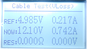
A cable test, this requires a stable USB power supply. First plug the load into the power supply, select a current level and hold down the button to record the reference. Next use the cable between the load and the supply (Do not touch the potentiometers) and it will show the cable and connection resistance.
Load testing
- Minimum stabilized current is about 0.4A, at lower current there will be a peak just below 5V
- Maximum current is about 3.2A
- It is fairly easy to adjust current to two decimal places, the 3. requires more care.
- Load have power and temperature overload protection.
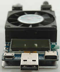
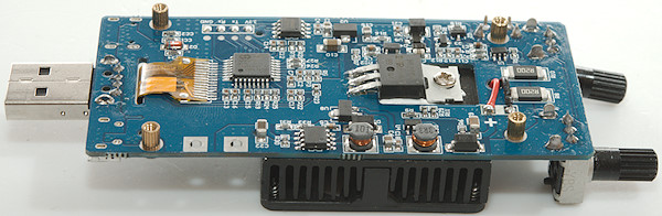
- The load has USB-A, micro usb and USB-C connectors, all in parallel.
- USB-C connector includes resistor to turn usb-c output on.
- USB load can trigger many normal usb fast charge schemes, but not USB-C PD.
- Fan is always on when load is powered.
- Display can be rotated, i.e. for view from connectors or from potentiometers.
- Current change during 60 minutes with 3A load at 9V is 0.033A, i.e. 1.1%
- Fine adjust is about 250mA range
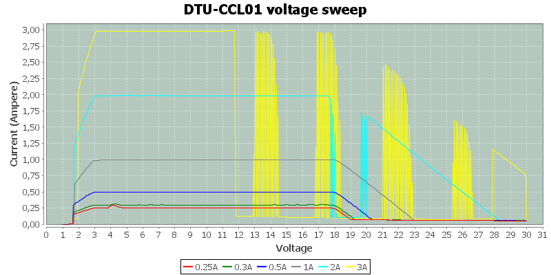
Some of the current curves looks a bit strange. The first point is that the load may handle 30V, but it only works below 18V, this is perfectly fine for most USB testing. The next point is the build-in protection, when the load gets too hot it turns it off for some time and then on again, this is especially obvious on the yellow curve, what is a bit strange is that sometimes it only turns off for a short time, other times for considerable longer time.
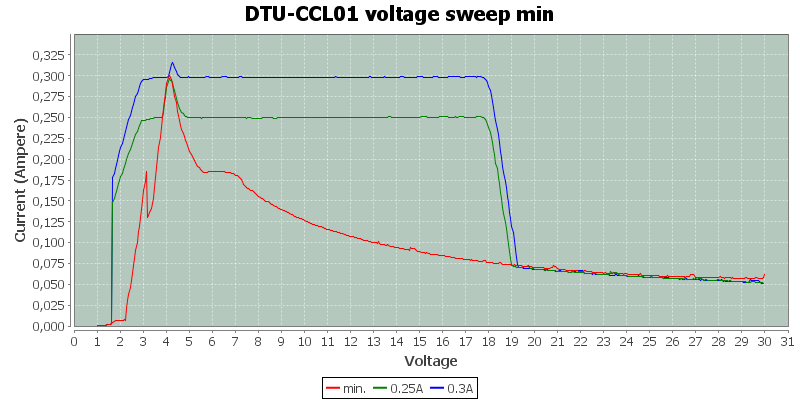
A closer look at the low current curves shows that the load is not good at this, there is a current spike just below 5V, it means for testing below 5V the minimum load current is about 0.4A, at 5V and higher it can go lower.
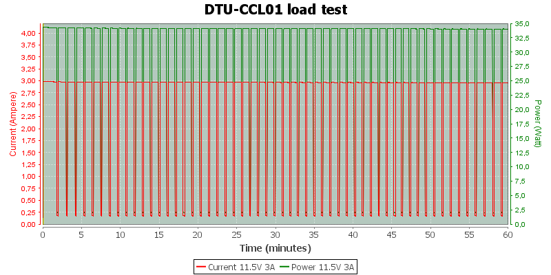
The load is rated for a maximum of 35W with a constant load of 25W, here I applied slightly below 35W and in about 1½ minute the load got to hot and took a break while cooling a bit down, the it engaged again. This continues in a cycle.
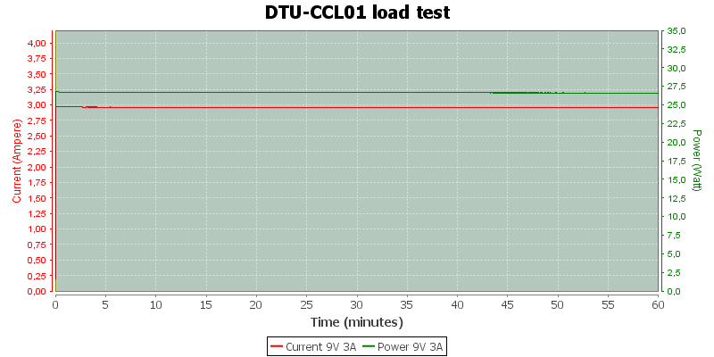
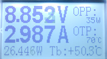
Reducing the load to 25W (Even a little bit above) with a 9V 3A test worked better, here the load could keep the temperature down. The display shows about 63°C (Ambient is about 25°C) and the overload is at 70°C.
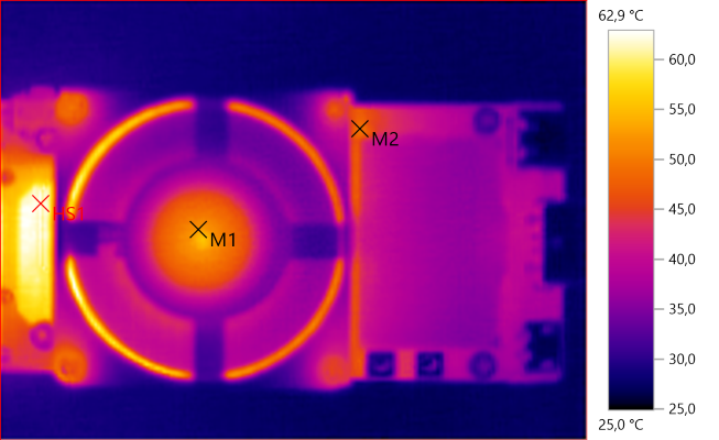
M1: 52.2°C, M2: 49.2°C, HS1: 62.9°C
HS1 is on the circuit board next to the heatsink and that temperature matches the display fairly well.
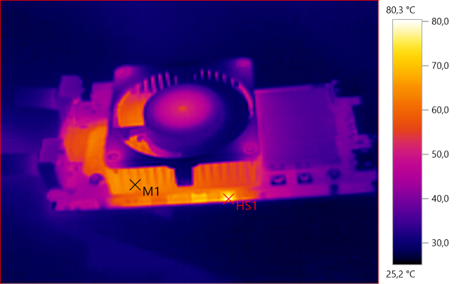
M1: 64.5°C, HS1: 80.3°C
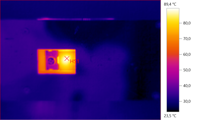
HS1: 89.4°C
The transistor is warmer (it is probably rated for 150°C inside).
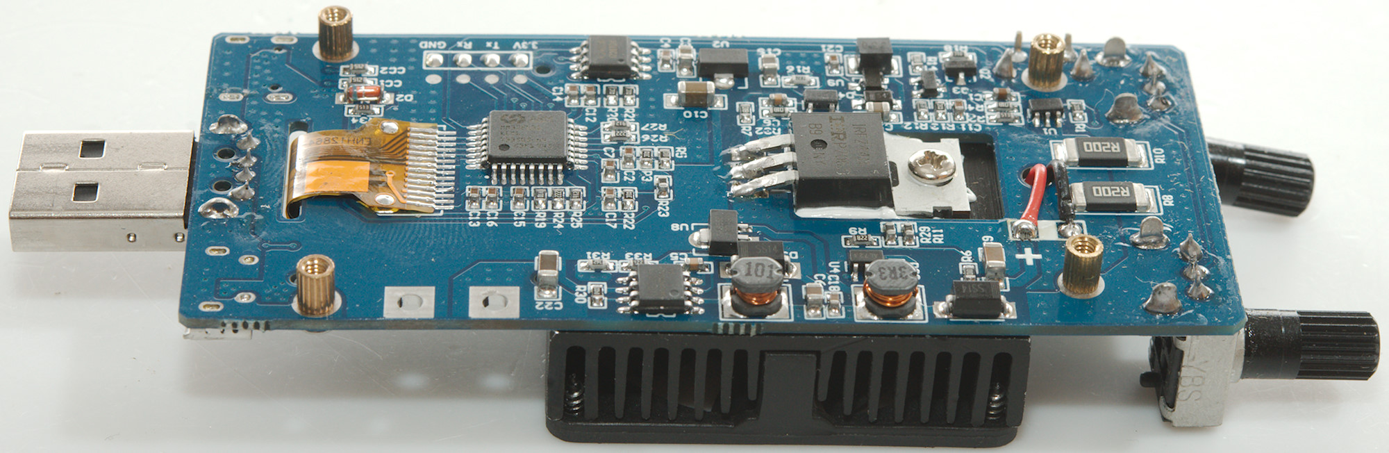
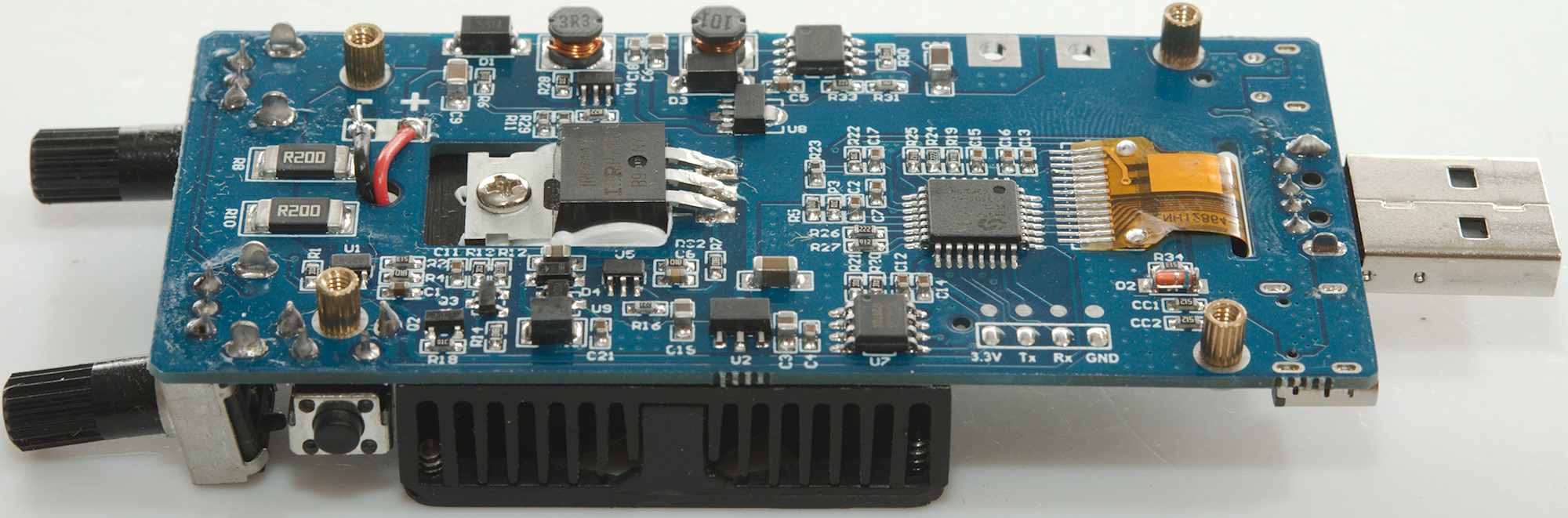
A look at the circuit
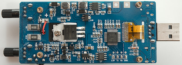
The load has a processor (ARM MM32F031 K6T6) that directly controls the display (There must be a controller in the display). There is an external EEPROM (U7: K24C08) for parameter storage. The internal power supply is fairly advanced with two switchers, one for the fan (U4: marked AL723) that uses a inductor and diode (d1) and one for the electronic (MC34063A) also using a inductor and diode (D3) and two linear regulators (U8: SE8550 & U2: SE8533).
The current sense resistor is two resistor in parallel (R8 & R10: 2x0.2ohm) with a OpAmp to amplify the signal (U1: marked CD53) and another (U5: marked CD53)to control the power mosfet (IRFZ44N).

Conclusion
The load works fine for testing usb power supplies, but the fast charge identification is not 100% reliable and it do not work up to the rated voltage of 30V or the maximum QC usb voltage of 20V (The trigger support 20V).
Even with these issues I will call it a fairly good load for usb, except USB-C PD that it do not support.