USB Load resistor Juwei 2.5-5-10ohm
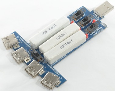
Official specifications:
- With switch can easily switch more current gear
- 1 separated 4 USB high-current output splitter
- Charging Accelerator Index (iPhone + Android)
- With switch control USB desk lamp, LED night light, camping light
- Test support micro USB data cable interface input / switching
- Test support mini USB data cable interface input / switching
I bought from ebay dealer: power116
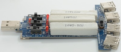
This load tries to be everything, it has 3 different resistors that can be switched in, it has 3 input connectors (USB A, mini and micro), it has 4 usb output connectors with different coding and it has a couple of white leds.
Usual the most interesting detail about this type of load is how hot they get, some power resistor has a working temperature between 200°C and 300°C when fully loaded.
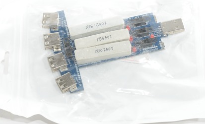
I got it in a plastic bag, there where no specifications or user manual included.
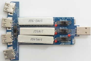
The actual load circuit is fairly simple: 3 resistors, each with a switch and a led (The 1A led did not work). On this load there is added four usb outputs with different coding (Samsung is missing, but there are 3 different Apple coding).
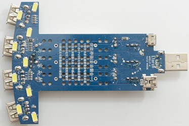
On this side the micro and mini usb connectors can be seen. The white leds are also placed here with a common 2.2 ohm dropper resistor, this resistor is going to be hot.
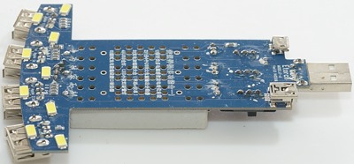
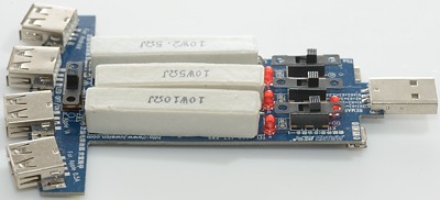
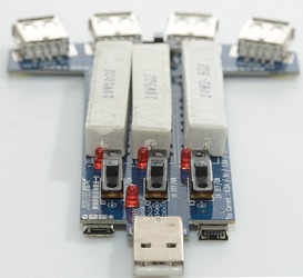
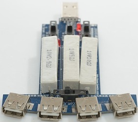
Load testing
- This type of load is only designed for 5V input.
- Current change during 30 minutes with 3.5A load is 0.022A, i.e. 0.7% (The change at 32min is not included)
- The led for 1A is not working.
- The current for the power led is 1mA and is always drawn.
- The switch for the white led is not reliable.
- The white leds uses about 0.8A
- The mini and micro inputs are in parallel with the usb-a input.
- USB output marked "Android" is coded as usb charger (DCP)
- USB output marked "Apple 2A" is coded as Apple 2.1A
- USB output marked "Apple 1A" is coded as Apple 1A
- USB output marked "Apple 0.5A" is unknown coding (i.e. out of tolerance)
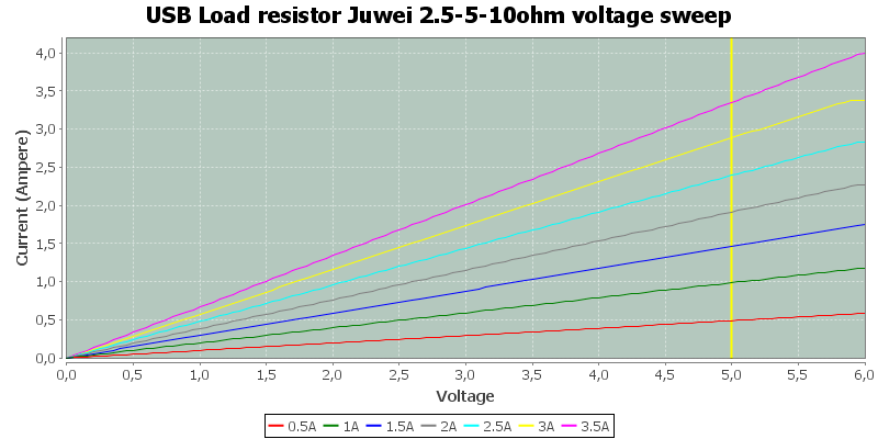
Being resistors the current will depend on voltage. The current is a bit lower than specified. The reason can be tolerance on the resistors, contact resistance in the switch and in the usb connector.
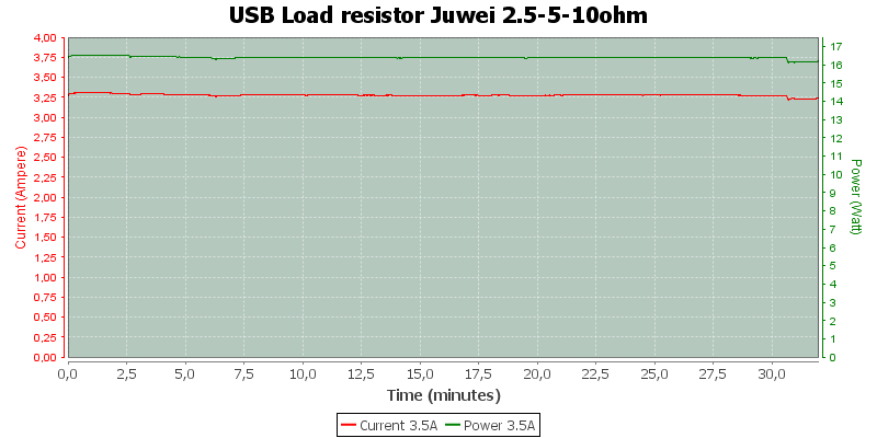
As expected the load current and power is stable with a resistor, except for a small change due to temperature.
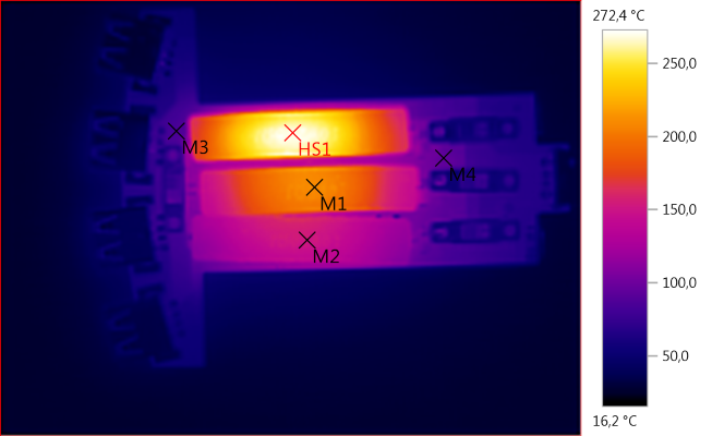
M1: 209,1°C, M2: 152,3°C, M3: 84,6°C, M4: 94,0°C, HS1: 272,4°C
The resistor with 2A gets close to its maximum temperature, it is a good idea not to touch the circuit board or the resistors while they are working.
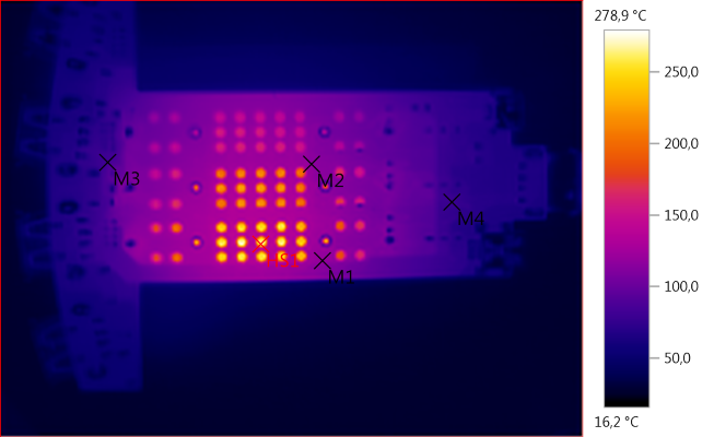
M1: 118,8°C, M2: 116,8°C, M3: 83,1°C, M4: 77,8°C, HS1: 278,9°C
The backside do also get fairly hot.
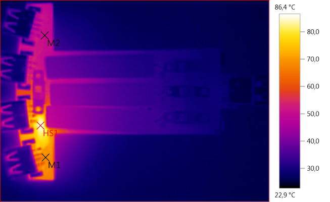
M1: 69,1°C, M2: 49,9°C, HS1: 86,4°C
What about the white leds? They do heat the circuit board a bit, but there is one warm point.
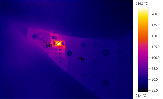
M1: 84,8°C, M2: 59,9°C, HS1: 216,5°C
To get a measurement of the hot resistor I covered all the leds with some fabric, then I could measure the resistor.
It is not going to have a long life at that temperature!
Conclusion
This load tries too many things at the same time, but do not really do any of them well.
The load part can be used, using a fan to cool the load is a very good idea.
The coded outputs can be used to check what coding a phone will accept, but I miss the Samsung coding.
I do not really know why the white leds are there and the dropper resistor gets way too hot.
The idea with multiple resistors that can easily be switched in is good enough, but this device is not very well made.


