QC3.0/2.0 trigger
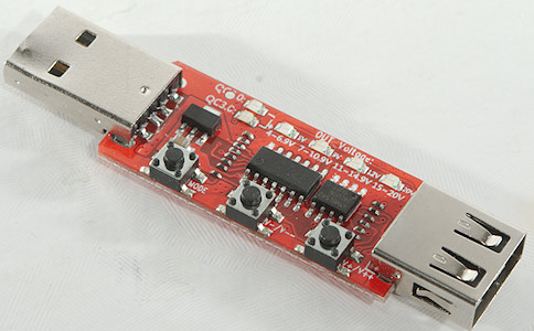
This is a Quick Charge trigger, it is mostly used for testing chargers, but can also be used to converter a QC charger into a power supply with other than 5V output.
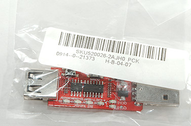
The trigger is delivered in a plastic bag, there was no box. As can be seen on the photos one of the usb connectors got slightly damaged in transit (I could fix it with somme pliers).

The circuit board contains: A unknown microcontroller, a EEPROM, a voltage regulator, a lot of very small resistors, indicator leds and 3 buttons. Some of the resistors are used to generate the QC voltage levels.

The mode button is used to selecte between QC2 and QC3.
The V+/V- will step voltage up/down:
In QC2 mode it is 5V, 9V, 12V and maybe 20V (If the charger supports it).
In QC3 mode it is in 0.2V steps from about 3V to 12V or 20V. Double click on +/- will change to auto increment/decrement, click again to stop.
The device will remember last selection when power is removed and automatic restore it again when power comes back.


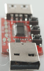
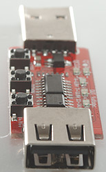
Measurements
- The marked voltage ranges on the leds are correct.
- Both QC2 and QC3 mode will remember settings, even when power is removed.
- QC3 mode will reset when QC2 mode is selected.
- QC2 mode will not reset when QC3 mode is selected.
- Resistance in plus connection is about 57mOhm including connector resistance
- Resistance in minus connection is about 50mOhm including connector resistance
- Resistance from usb solder blop to solder blop is 2.5mOhm on minus.
- Resistance from usb solder blop to solder blop is 13.5mOhm on plus.
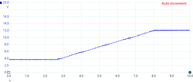
A double click on the V+ button will start the increasing ramp in QC3 mode, press again to stop the ramp. The ramp needs about 5 seconds to go from lowest to highest voltage. I tried this on a couple of different QC3 chargers and the time was about the same on all.
The trigger will continue to send increase pulses, until V+ is pressed again.
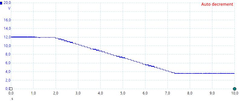
A double click on the V- button will start the decreasing ramp in QC3 mode, press again to stop the ramp. This also takes about 5 seconds.
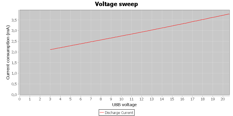
Current consumption of trigger. This depends a bit on voltage.
Conclusion
The trigger works fine, but I am not too happy about the usb output connector, it is way to easy to fry a device that cannot handle the full QC voltage.
To get lower DC resistance for testing, it is easy to solder some thick wires on it and bypass the second usb connector and thin usb wires.
I will call it a good device for testing, but be aware that it can easily fry a 5V usb device.


