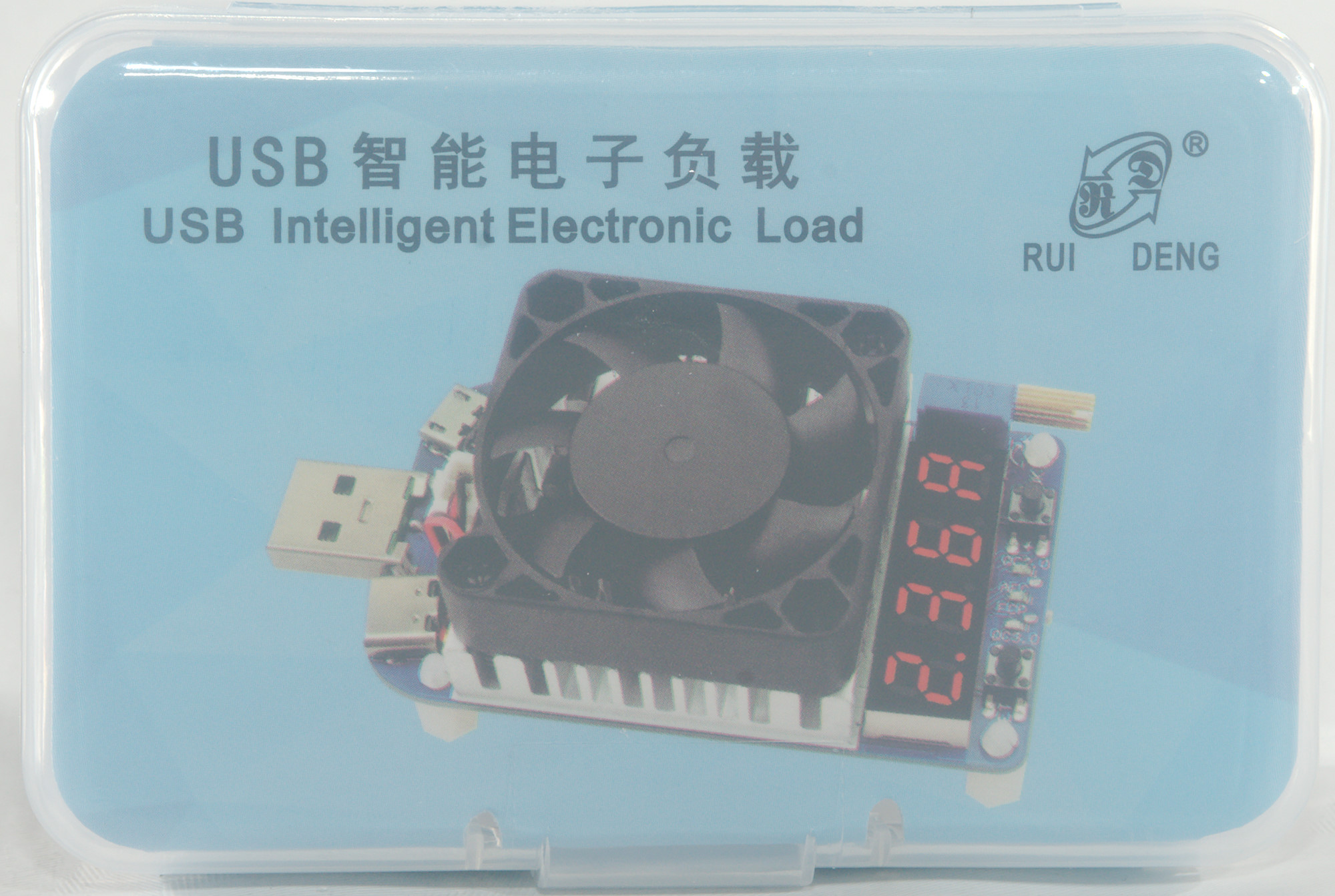
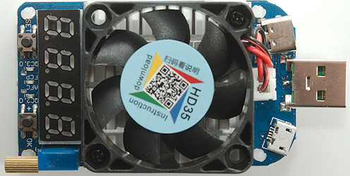
RD Electronic USB load HD35
Official specifications:
- Rated operational voltage: DC 4-25.0V
- Max discharging power: 35W
- Rated operational current: 0.25-5.00A (when fan dont work, the minimum constant current is 0.05A )
- Fan Speed: Large size intelligent temperature control fan, speed 8000±10%RPM
- Constant current resolution:±1% +3 digits
- Heat dispatch method: intelligent temperature control fan + All aluminum fan
- Working temperature: -10°C ~ 40°C
- Adjustable potentiometer: Precision multiloop adjustable potentiometer
- Display mode: 4 digit LED tube
- Expansion port: Micro USB port, Type-C port
- Trigger support: QC2.0 (QC2.0 5V, 9V, 12V and 20V), QC3.0, Huawei FCP, Samsung AFC 9V
I got it from Aliexpress dealer: RD official store
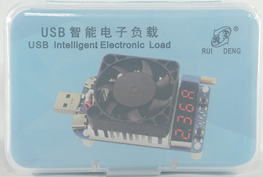

I got it in the usual Styrofoam box (That is RD's standard packing) together with some other stuff, inside the box it was in a transparent plastic box.
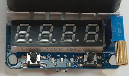
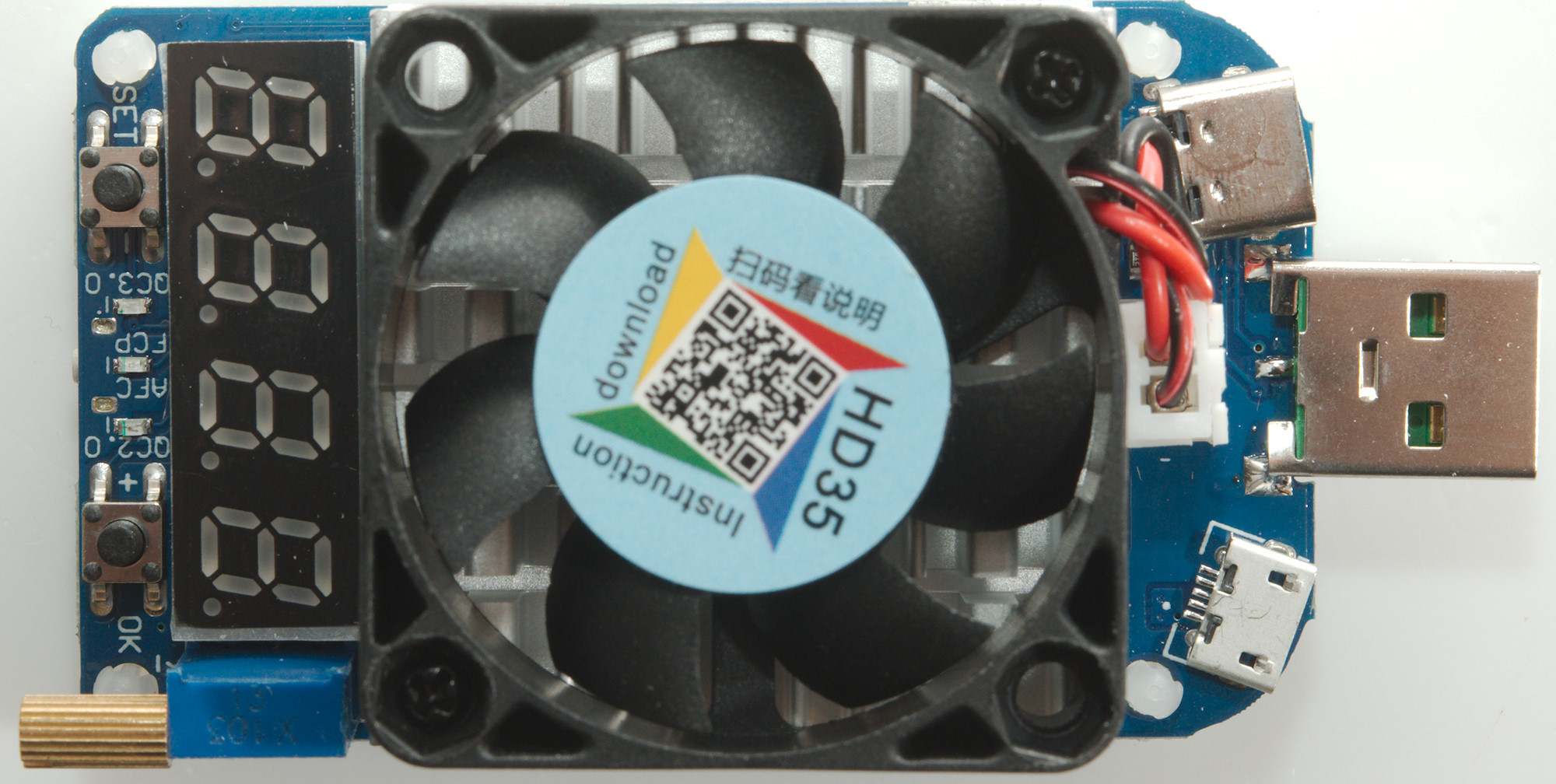
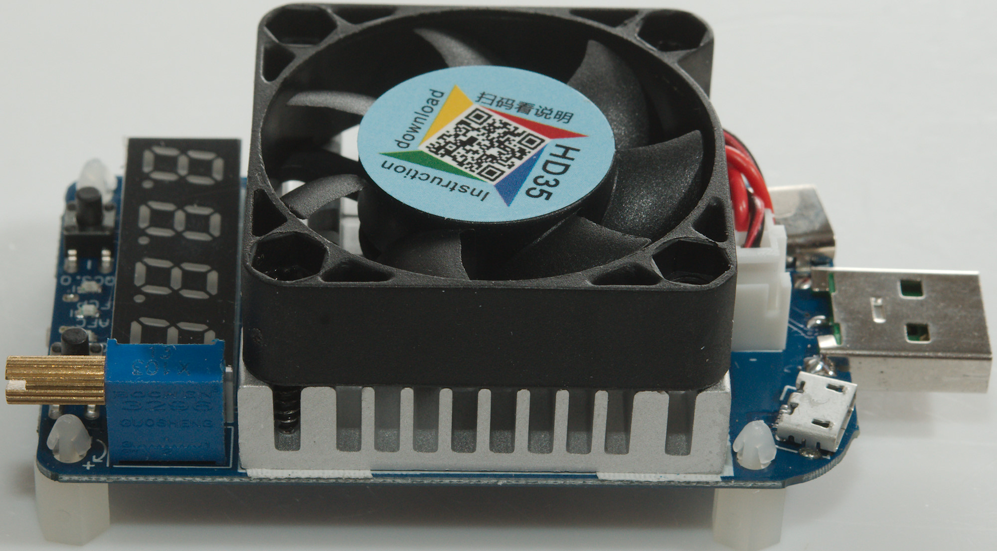
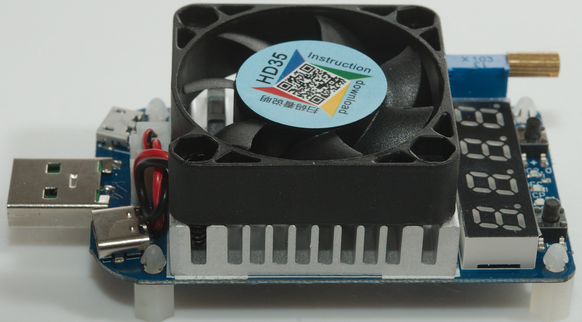
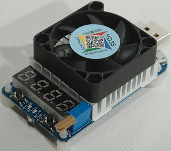
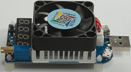
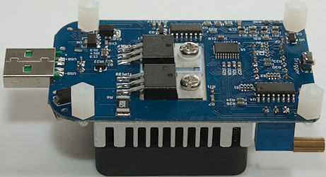
At one end is the 3 buttons (One below the circuit board), the current adjustment, the display and 3 leds for fast charge protocol.
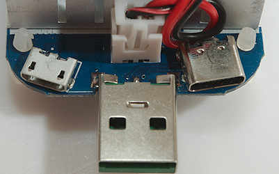
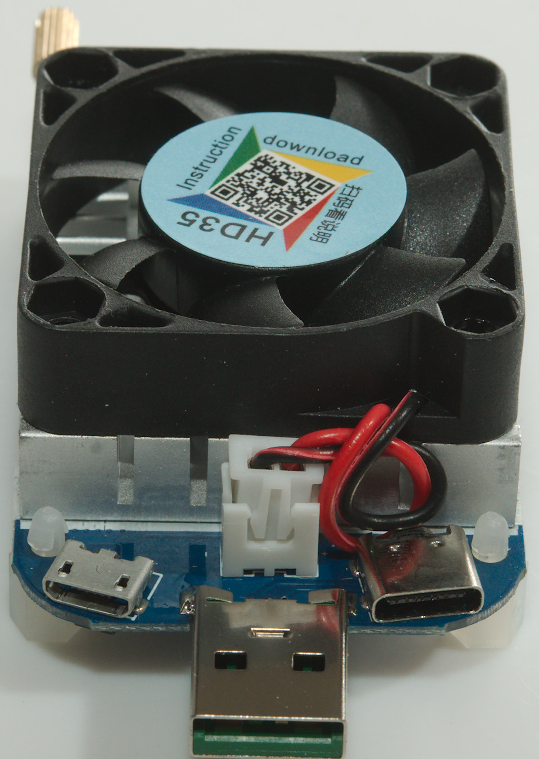
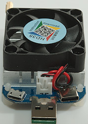
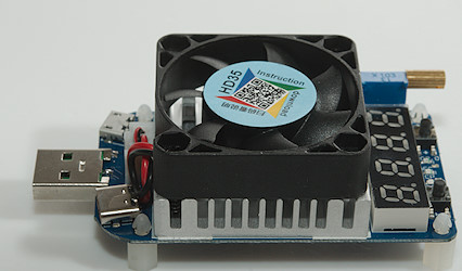
At the other end is the 3 usb connectors (Micro, A and C), between is the heatsink and fan.
I will take a closer look at the circuit further down.
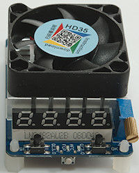
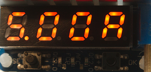
Display with current, the value will flash when load is off.
Load can be configured to automatic turn on when power is applied.
Power.
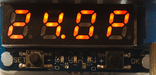
Voltage.
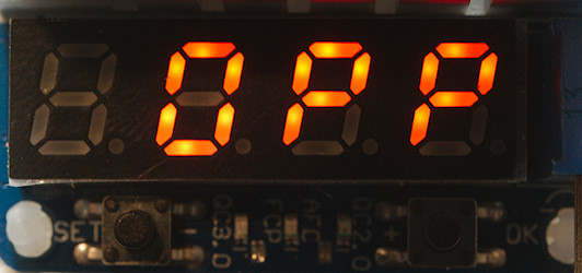
Over Power Protection, this will show when calculated power is above 25W, the load will not not turn on.
In can be configured to automatic turn on when load is 25W or lower.
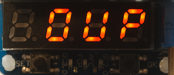
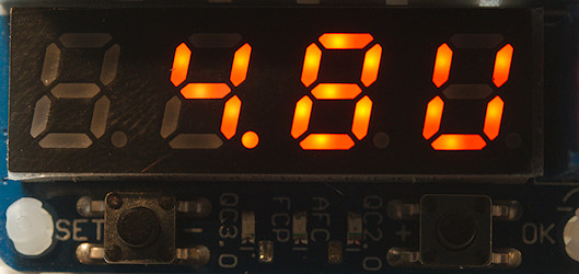
Over Voltage Protection, this happens between 25V and 30V
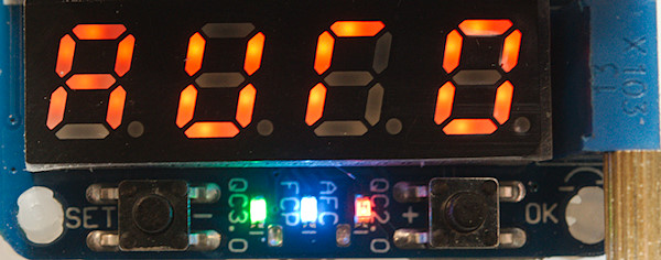
Auto trigger mode, it will scan for the supported protocols.
Here it shows QC3.0 and QC2.0 is found on the leds.
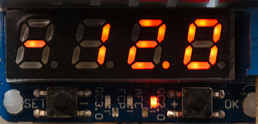
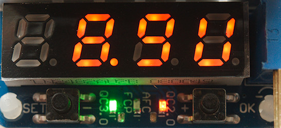
Here QC2.0 12V is selected, the minus sign shows it is a Quick Charge. When a fast charge trigger is active that led will flash, I took the picture when it was on.
The user interface for testing and activating the triggers is not the best, but it works.
Load testing
- Current resolution is 0.01A
- Voltage resolution is 0.1V
- Power resolution is 0.1W
- Internally current is adjusted in 0.01A steps, it is not analog!
- Load is rated to handle 30V before being damaged, load shows OUP between 25V and 30V
- Current adjustment range is from 0.00A to 5.09A, but supported range is from 0.05A to 5.00A
- The load has USB-A, micro usb and USB-C connectors, all in parallel.
- USB-C connector will not turn USB-C output on!
- The support for QC3 only goes down to 4.1V.
- Load can store a fast charge state and automatic activate it when powered (Vere nice for testing).
- Voltage display shows voltage at input, any voltage drop is due to connector and cable resistance.
- I got about 0.11V drop for connection and other resistance in usb load at 5A (Current in on A, check on C).
- Current change during 60 minutes with 1.4A load at 24.9V is 0.01A, i.e. 0.6%
- Current change during 60 minutes with 5A load at 6.9V is 0.003A, i.e. 0.06%
- The adjustment is a multiturn potentiometer and the display will show the selected current.
- The fan is audible, but not loud, it starts and stops as required (This is a bit annoying).
- Current when off is about 10mA for the electronic and display.
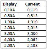
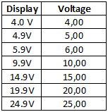
Both current and voltage readout has good precision, but at 5A it is slightly outside specifications.
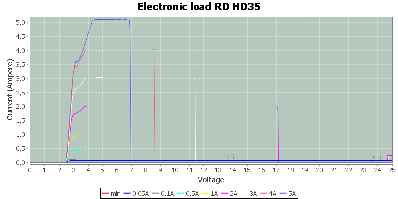
Due to the power limit of 35W it is not possible to test with high current and high voltage, here I had enabled automatic recovery, i.e. load would turn on when the voltage was low enough. On many of the high current traces the fan was running when I started at the high voltage, but would stop when the load had cooled down.
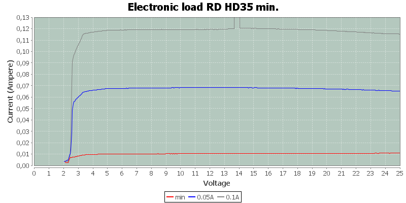
Here is a trace with adjustment in minimum position and low current traces. The load has an offset of some mA at these low currents.
The fan started shortly in the 0.1A trace and it uses more than 0.1A
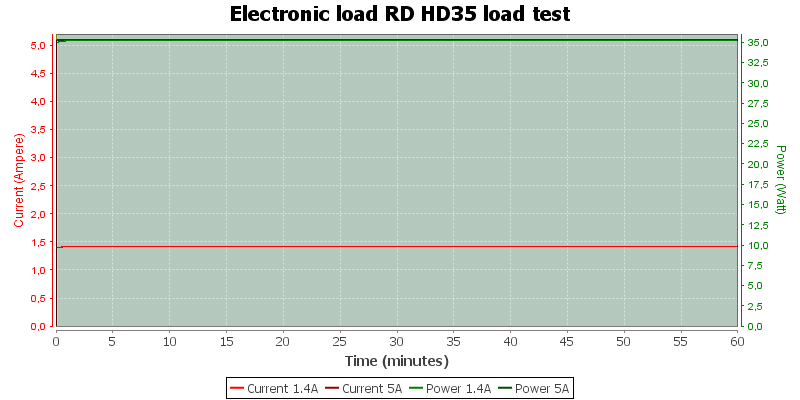
I tried two 1 hour test, one at maximum voltage (I used 24.9V and 1.4A) and one at maximum current (I used 6.9V and 5A).
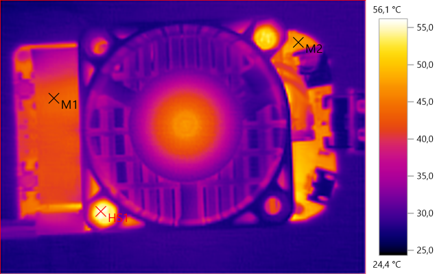
M1: 43.1°C, M2: 47.3°C, HS1: 56.1°C
First set of thermo photos is from 24.9V 1.4A test
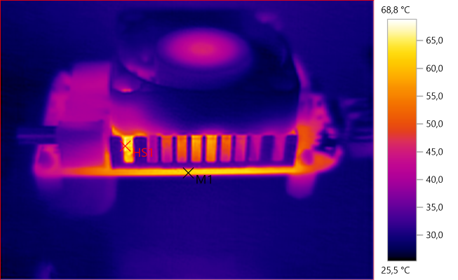
M1: 62.2°C, HS1: 68.8°C
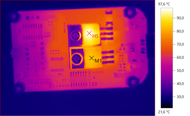
M1: 83.9°C, HS1: 97.6°C
Both transistor and regulator warms up with high input voltage.
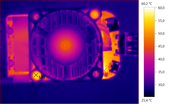
M1: 55.6°C, HS1: 60.2°C
Next set of thermo photos is from 6.9V 5A test
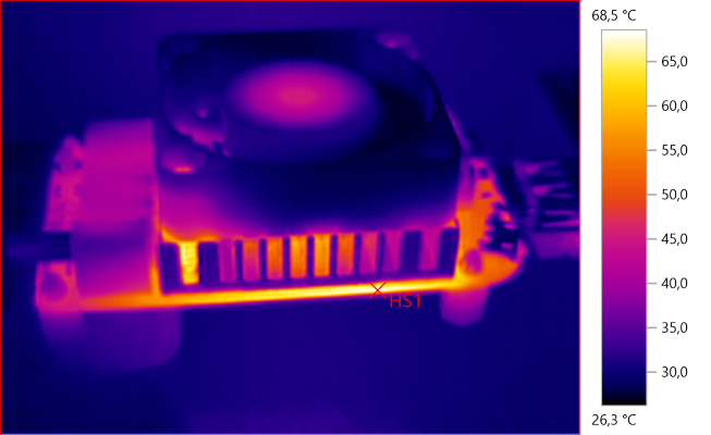
HS1: 68.5°C
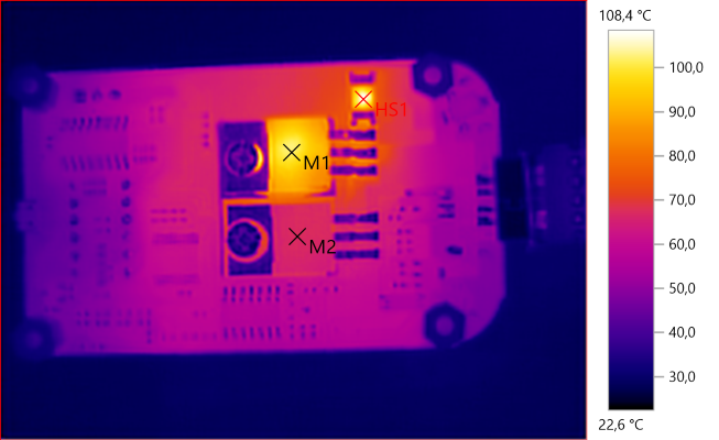
M1: 101.9°C, M2: 67.1°C, HS1: 108.4°C
With lower input voltage the transistor must handle all the power and gets a bit warmer, the shunt resistor do also get warm at 5A
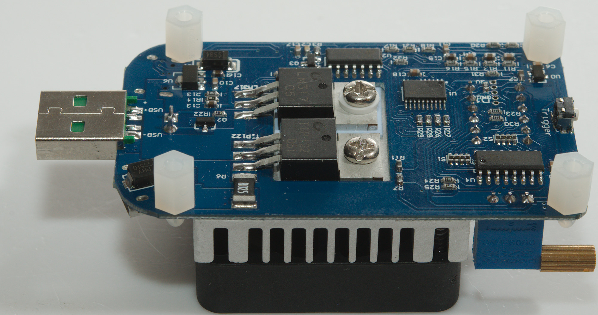
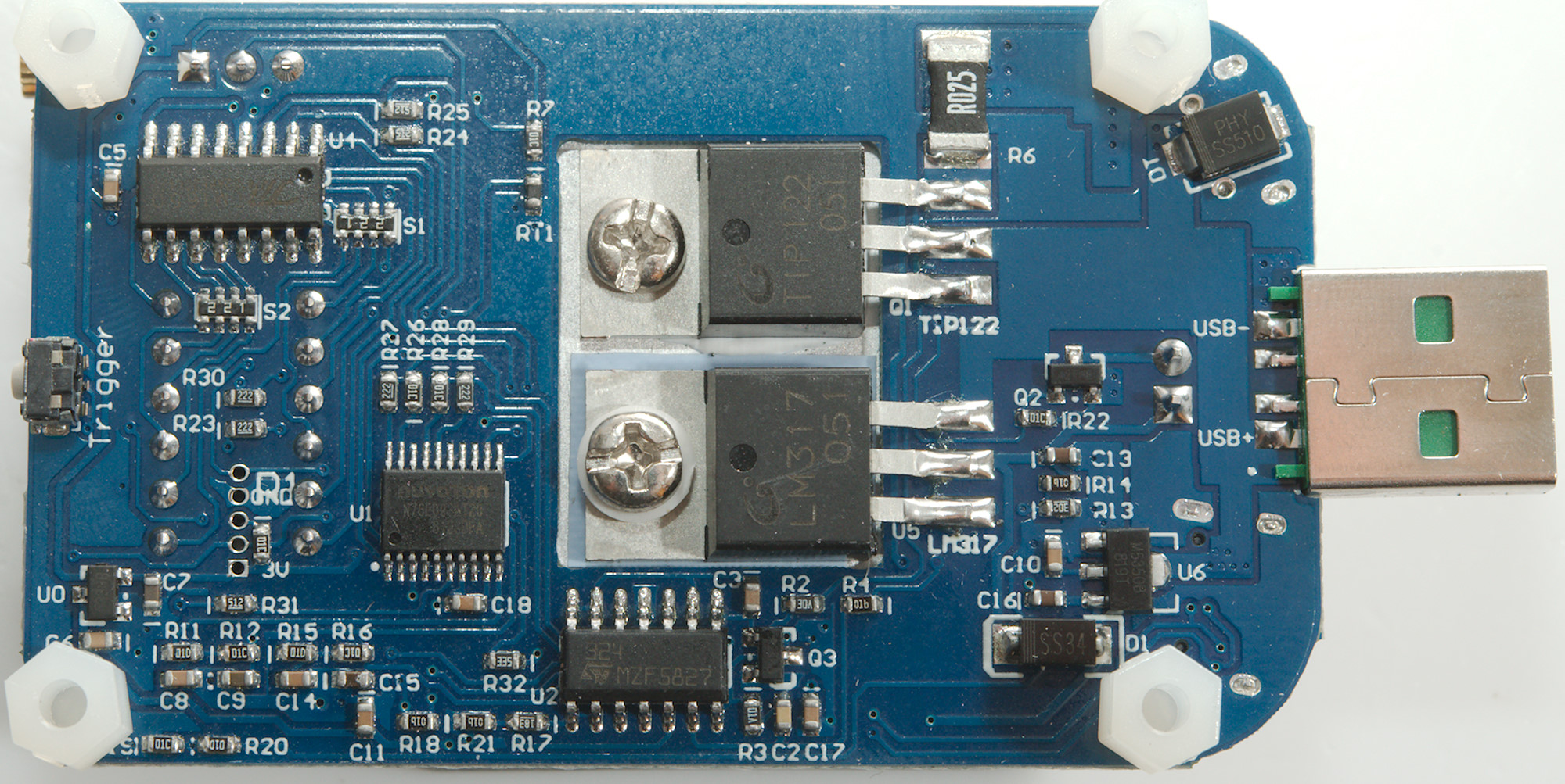
A look at the circuit
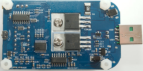
The transistor (TIP122) is the load element, it uses a resistor (R6: 0.025ohm) to sense the current. The fan is a 5V version and has its own regulator (LM317), at high input voltage it must handle some power. Turning the fan on/off is handled by a small transistor (Q2), the temperature sensor is very close to the TIP122 transistor and is a NTC (RT1) that is connected to the MPU.
The electronic has its own voltage regulators (U6: M5350B 5V, U0:5333B 3.3V). The control of the load current is done with some OpAmps (U2: Marked 324 / MZF5827). The brain in the circuit is a 8051 microprocessor (U1: N76E003AT20 18KB Flash, 1k RAM, 12 bit ADC). For the display a special controller IC (TM1650) is used.
Why 4 OpAmp, a load only needs one OpAmp. A look at the circuit shows some filters connected to the MPU on U7. One filter is R11, R12, C8 and C9, the other filter is R15, R16, C14 and C15.
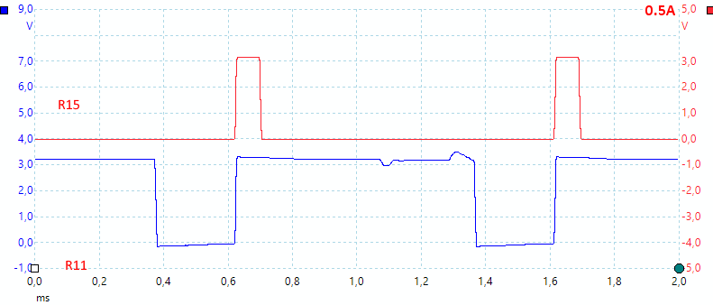
Filter input from microprocessor at 0.5A
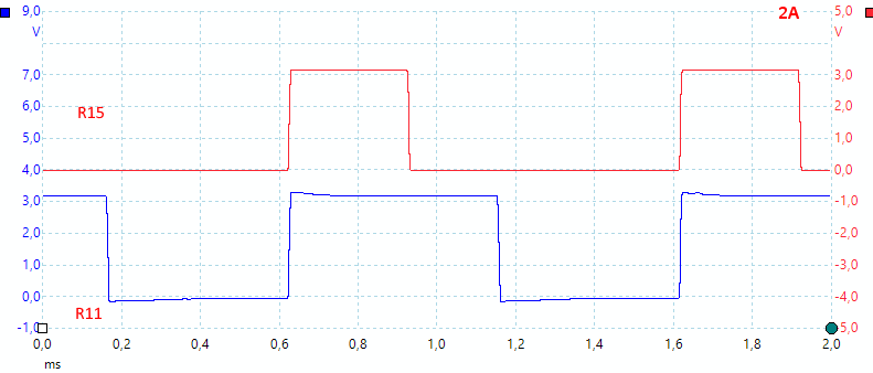
Filter input from microprocessor at 2A
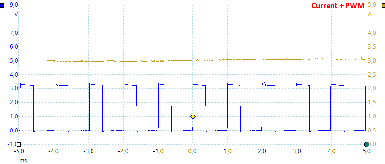
The above PWM frequency is 1kHz, is there any trace of it on the output? To test that I used my current clamp to check the load current, there is nothing in the output that look to follow the PWM (Blue trace).
Conclusion
The load works fine and with the multiturn adjustment and display it is easy to adjust. It has no problems handle the rated 35W power. It is not for low loads, the display and adjustment do not have resolution for it and it also need some minimum current to work.
It is a interesting design choice that the analog current setting is sampled by the microprocessor and then output as two PWM channels that is filtered and mixed, before being feed to the load regulation.
The fast charge trigger works fine and can current settings can be saved, this makes it ideal for testing multiple power supplies. I could have wished for a bit better user interface.
With USB-C I am missing the ability to turn outputs on (It is just a resistor), this will limit its usefulness for USB-C.
Notes
When I saved power on fast charge trigger, I could not disable the "fast charge" part again. It is not a real issue, because it is possible to update the saved trigger and for chargers without fast charge it will just work without.
The load was supplied by Rui Deng (RD) for review.
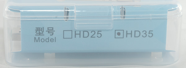
The company also has a 25W load, main difference is the fan.