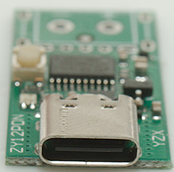
yzxStudio ZY12PDN PD trigger
This device is a trigger to access PD voltages on a USB-C charger, it requires a USB-C cable to work. The trigger exist in a couple of different versions, depending on output configuration: USB-B, terminals or soldering (I got the last one).
I got it from Aliexpress dealer: Hennybig Fish Store
I got it in a envelope without any instructions. There was some instructions on the dealer website, it was English words, but not easy readable.
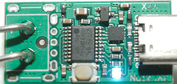
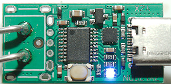
The user interface is a single button and a multicolor led. Pressing the button will step between available voltages, each step has its own LED color. The most common sequence will be: 5V, 9V, 12V, 15V, 20V.
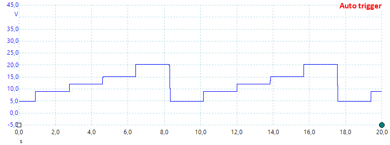
Holding the button down when powering on will change to programming mode where initial voltage or auto trigger can be selected, the selection is stored by holding the button down again. The programming is voltage based and has these steps: 5V, 8-10V, 11-13V, 14-16V, 18-20V, maximum voltage, auto trigger.
Measurements
- The trigger can be programmed to start at specific voltage.
- It will enabled output voltage on a PD supply when connected.
- For maximum current check the specifications of the used power supply
- Power consumption of trigger is about 10mA
- Trigger uses 5A mode if available.
Voltage drop including USB-C connections:
Plus: 80mV at 3A -> 27mOhm
Minus: 72mV at 3A -> 24mOhm
This is a low resistance and much of it is probably from the connections.
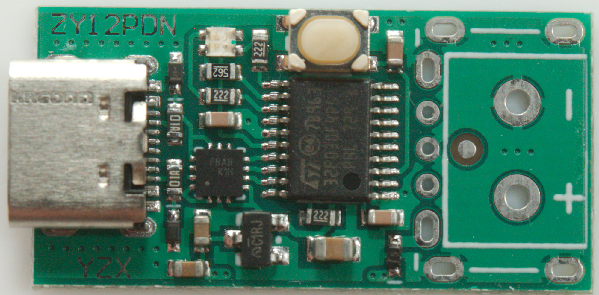
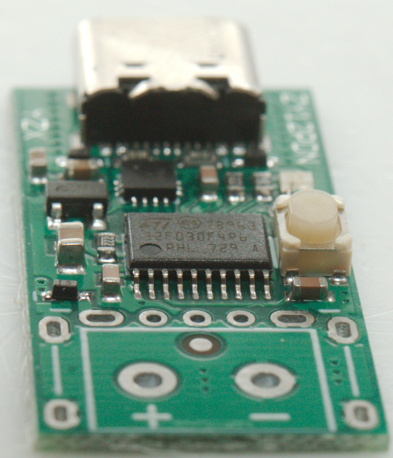
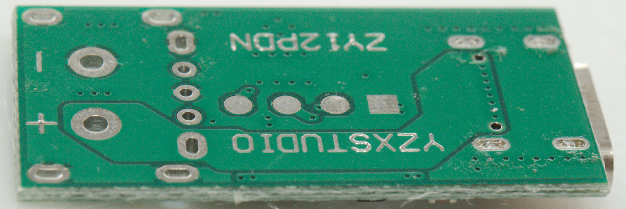
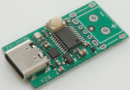
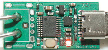
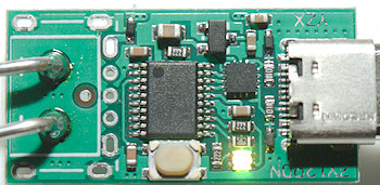
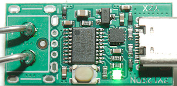
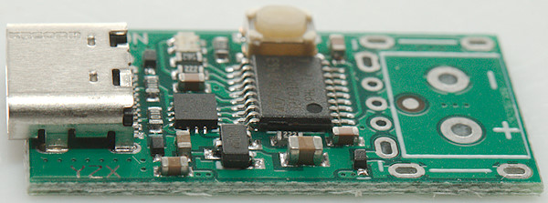
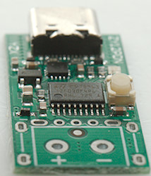
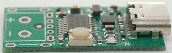
A closer look
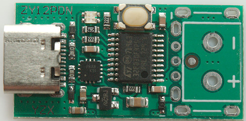
The circuit consist of a PD controller chip, a microprocessor (ST: 32F030F4P6) and a voltage regulator. The LED is a pack with 3 colored LEDs inside.
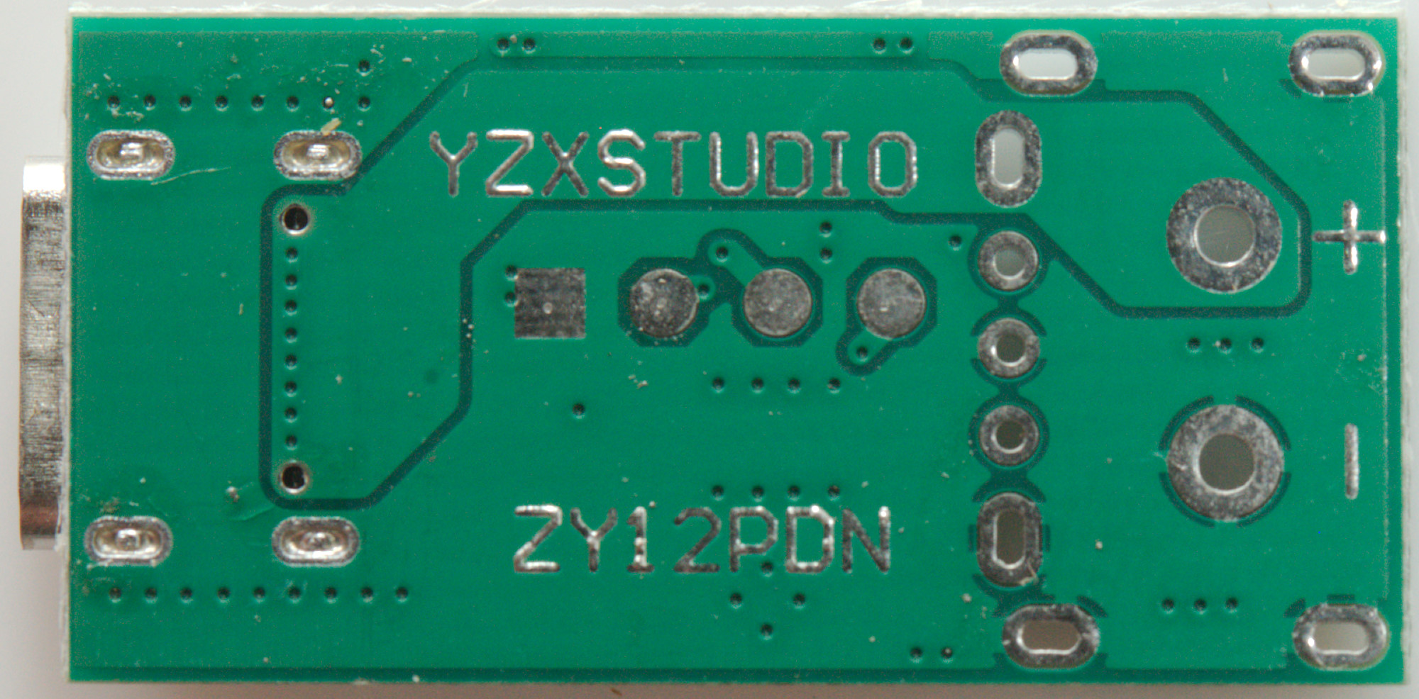
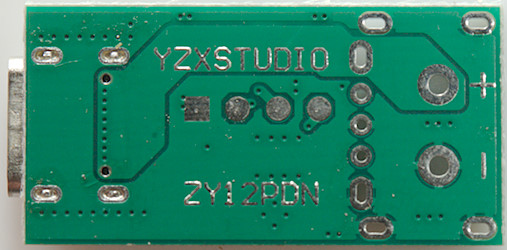
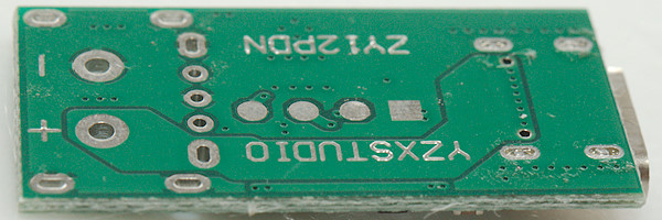
The circuit board has holes for either a USB socket or terminals.
Conclusion
This is a simple PD trigger with the possibility to program it for specific voltages or for looping through all the voltages.
The colored LED may not be the best way to indicate voltage, if I am going to use it with programmed voltages I would write the voltage on the circuit board.