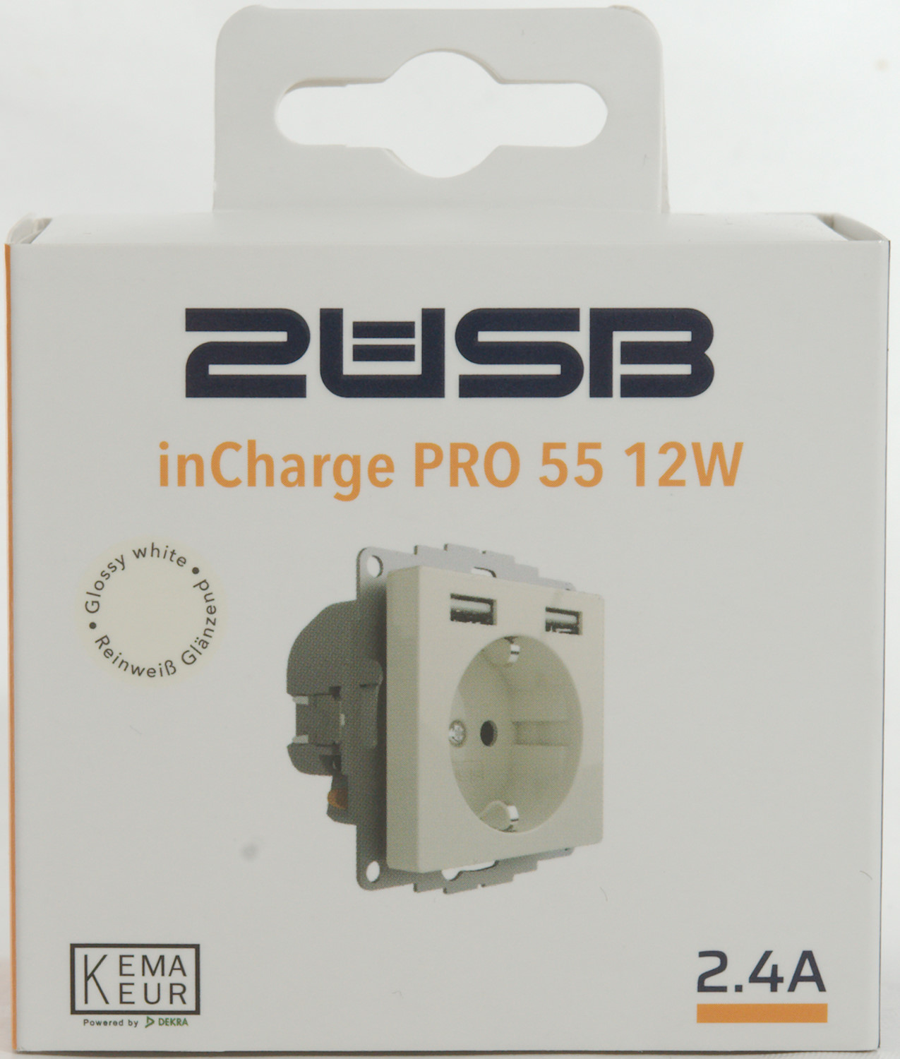
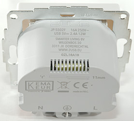
2USB inCharge PRO 55 12W
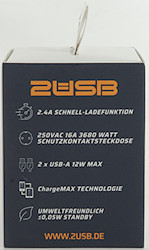
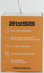
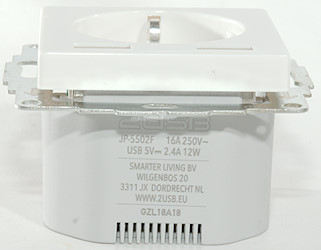
Official specifications:
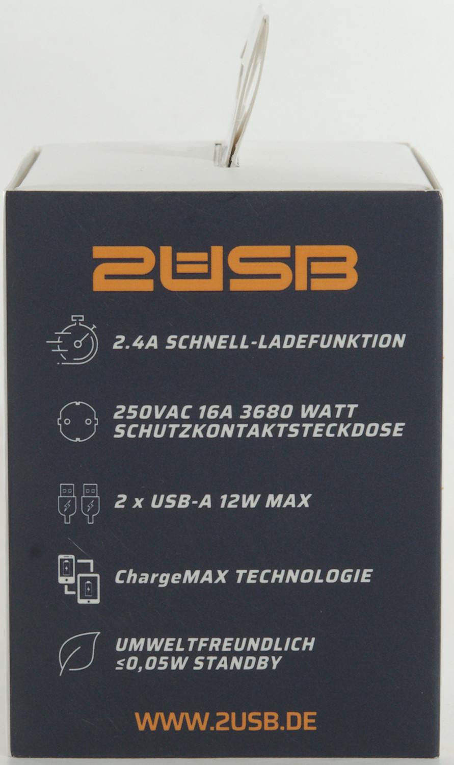
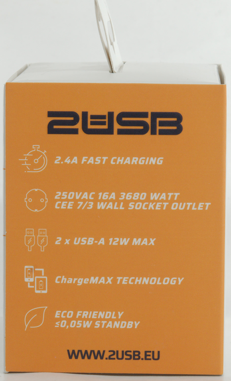
- Input voltage: 120 - 250V 50Hz
- Input current: 0.5A
- Output voltage: 4.75 - 5.25V
- Output current: 0.01 - 2.4A
- Output power: 12W
- Energy efficiency >=86%
- Standby power loss: <=50mW
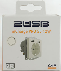
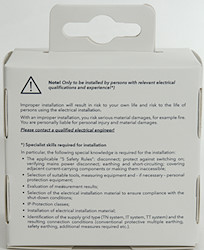
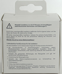
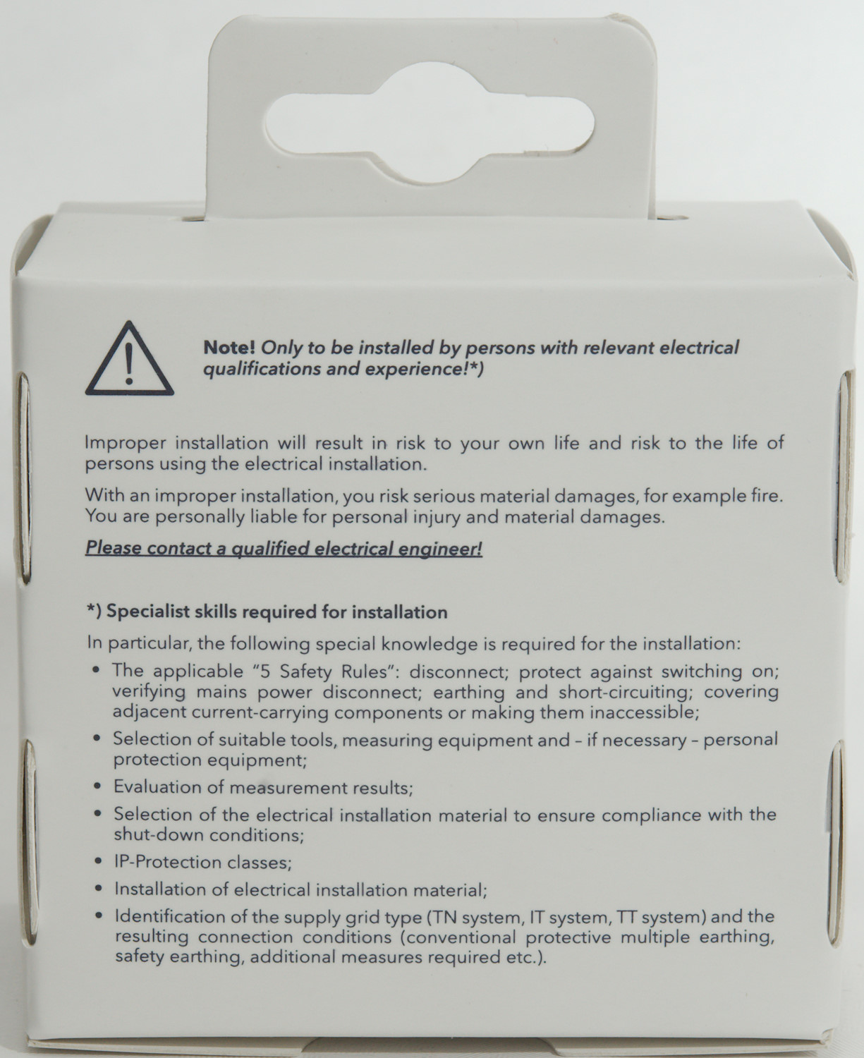
When I started to open the box there was more instructions inside, both in English and German.
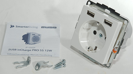
The box contained the charger, a instruction sheet and some clamps that can be used for mounting it.
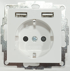
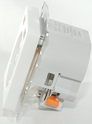
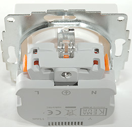
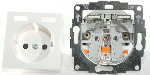
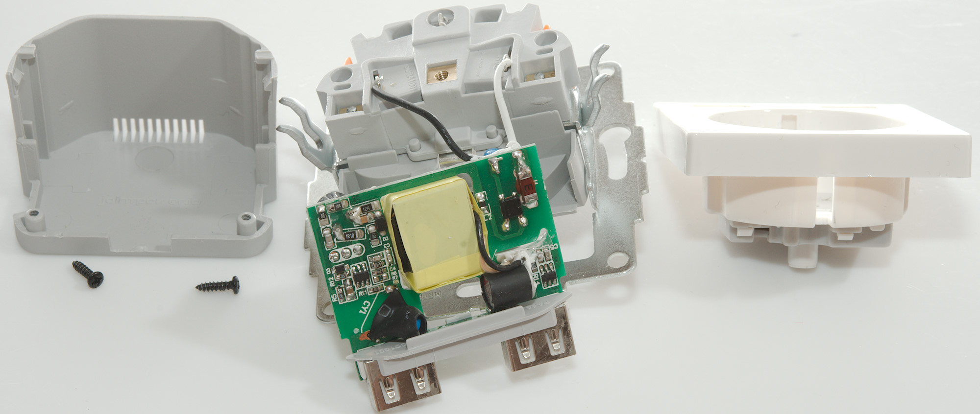
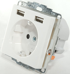
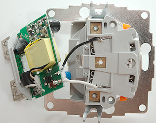
The front can be removed by loosing one screw, the mains is still mostly protected.
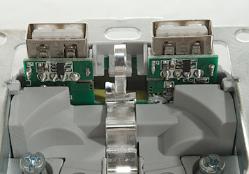
Part of the usb circuit board can be seen when the front is removed.
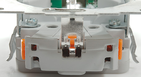
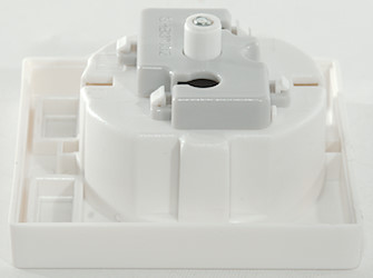
The mounting clamp
Measurements
- Power consumption when idle is 0.06 watt, that is about 0.5kWh/year
- Both USB outputs is auto coding with DCP, Samsung and Apple 2.4A
- USB outputs are in parallel.
- Weight: 97g
- Front is 55.3 x 55.3mm, metal plate is 71 x 71mm
- Wall box hole: min. 53x52mm with a depth of 32mm (Instruction require 40mm)
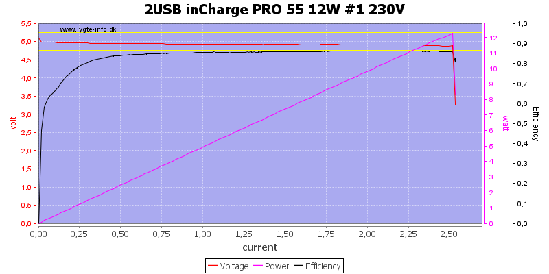
Output can deliver a bit above 2.5A, this is very good for a 2.4A rated output

The output output is the same on the other plug.
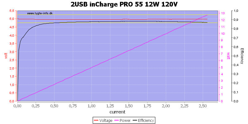
The socket is not rated to work at 120VAC, but it will do it.

Running the two outputs in parallel do not increase power.
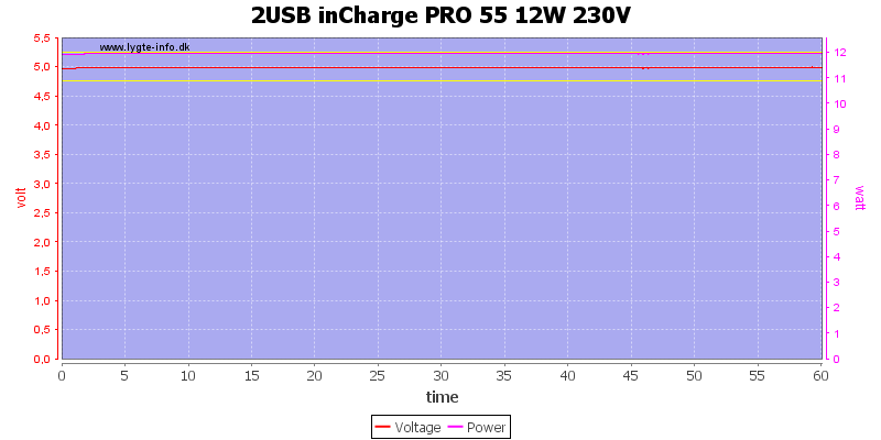
The charger has no problem delivering 2.4A for one hour.
The temperature photos below are taken between 30 minutes and 60 minutes into the one hour test.
My test is done in free air, this charger is supposed to be mounted in a wall, this can mean better or worse cooling.
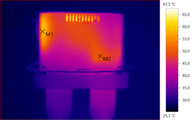
M1: 57.9°C, M2: 49.8°C, HS1: 67.5°C
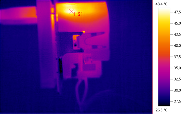
HS1: 48.4°C
HS1: is the rectifier transistor.
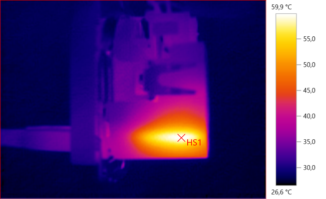
HS1: 59.9°C
The heat in this corner is either from the switcher transistor or from the snubber network (Maybe a combination).
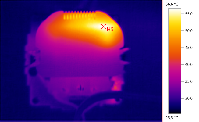
HS1: 56.6°C
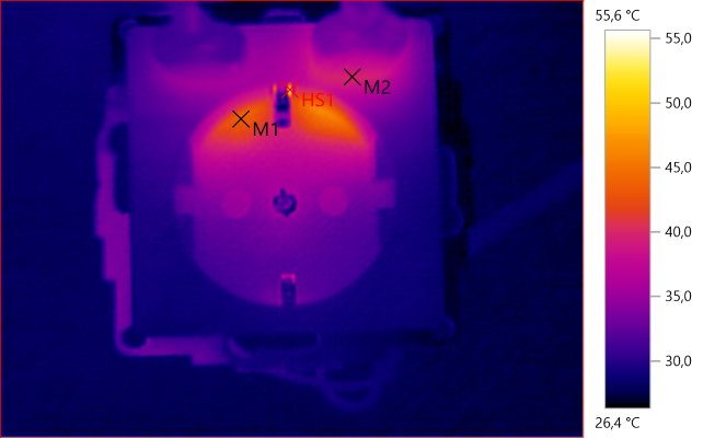
M1: 43.3°C, M2: 39.7°C, HS1: 55.6°C
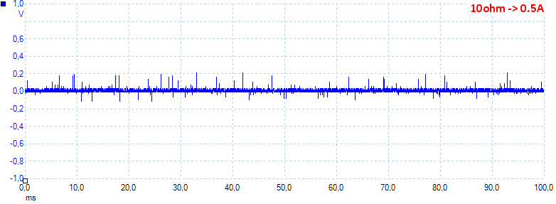
Noise at 0.5A load is: 20mV rms and 476mVpp.
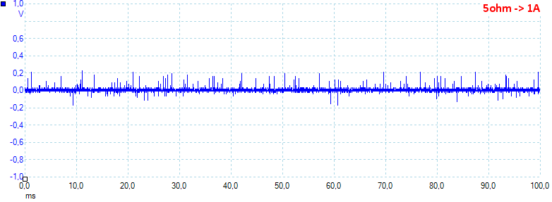
Noise at 1A load is: 26mV rms and 569mVpp.
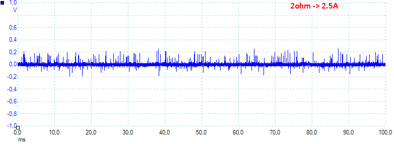
Noise at 2.5A load is: 32mV rms and 604mVpp.
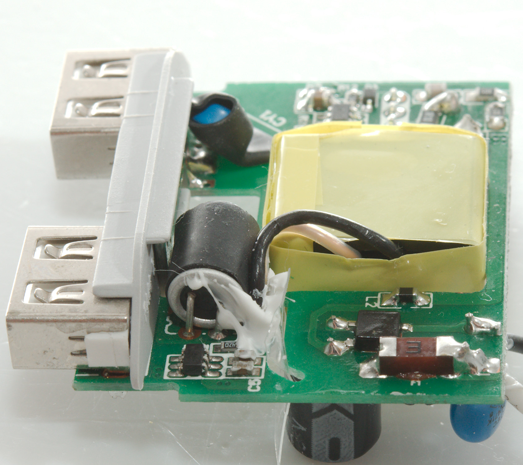
Tear down
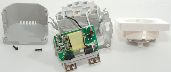
I had to remove two small black screws then I could unclip the back and pull the usb circuit out.
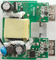
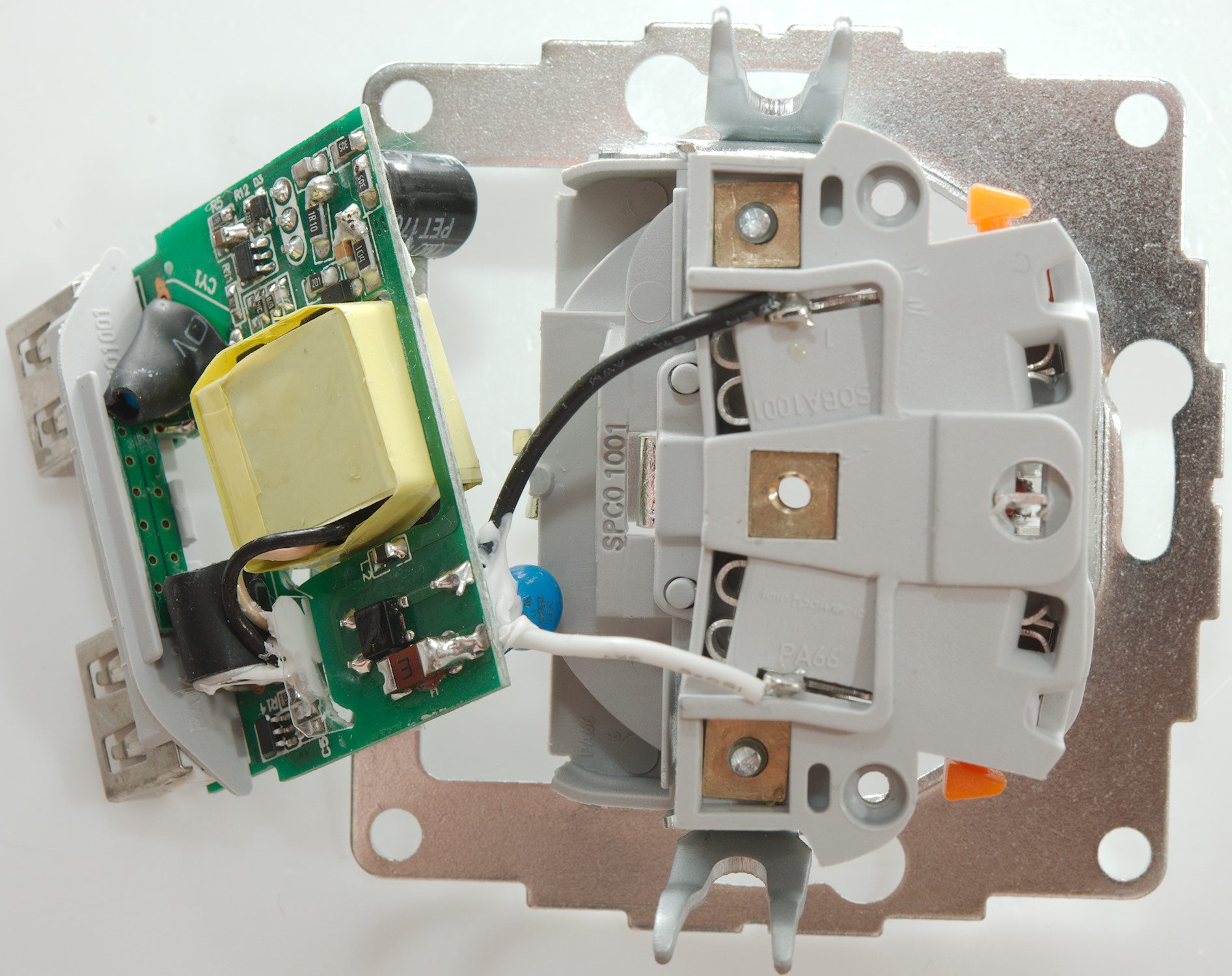
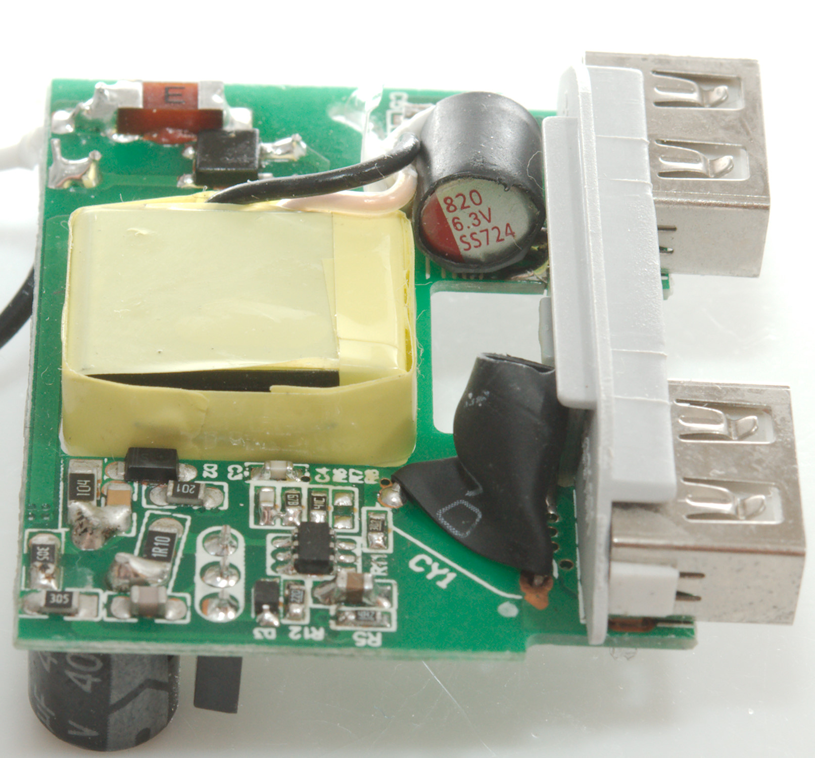
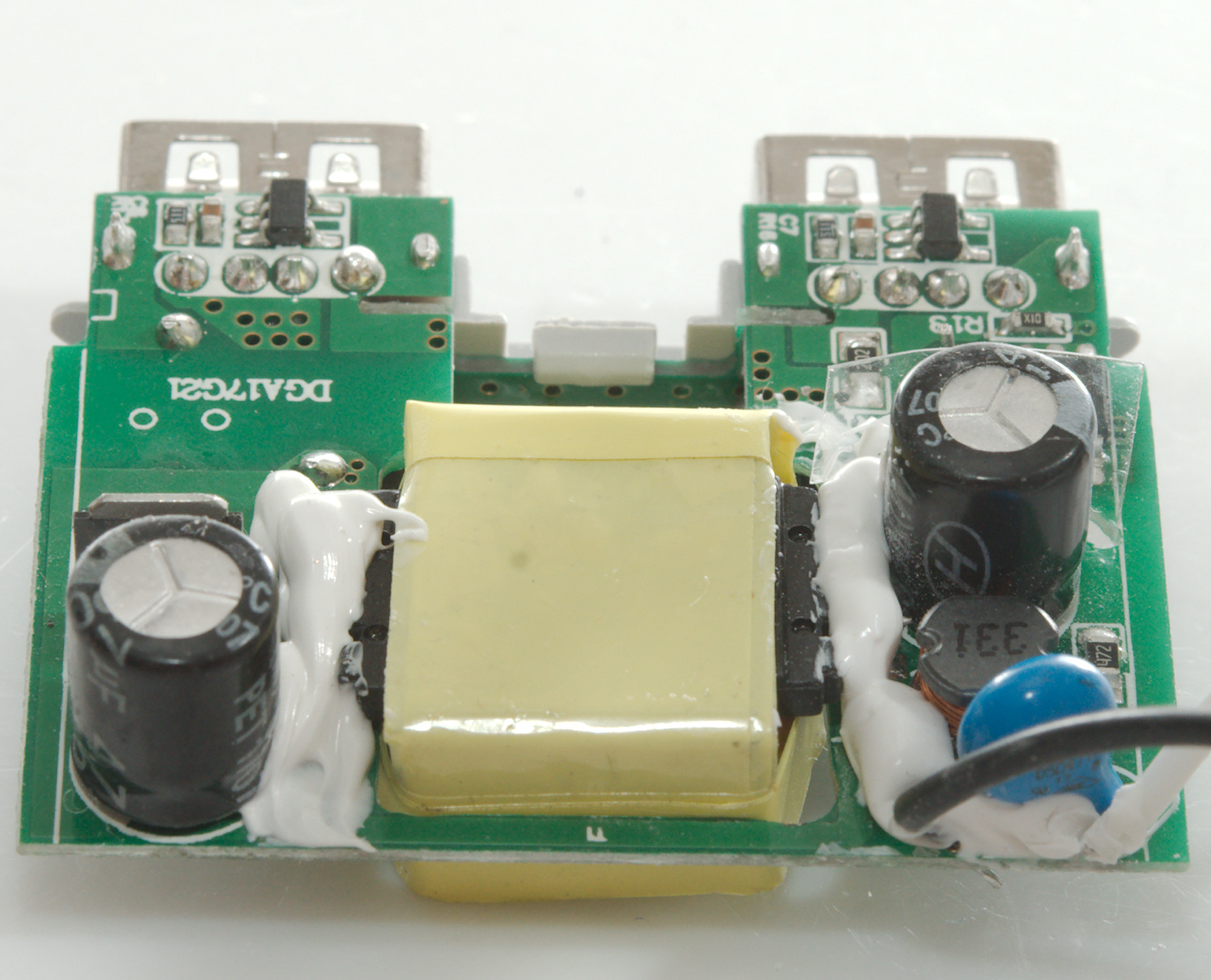
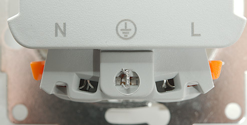
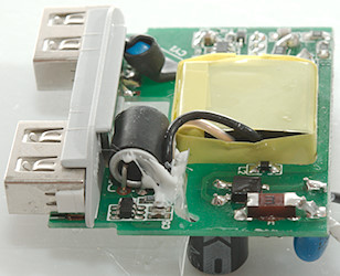
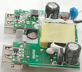
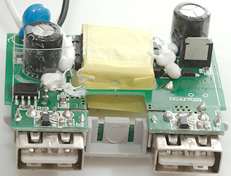
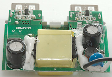
The mains part of the circuit board is near the transformer. Where the mains wires are connected is a MOV across the mains, there is a inductor between the two mains smoothing capacitors (One on each side of the transformer). On the other side of the transformer is also a switching transistor (Q1).
On the low volt side is a rectifier transistor and a auto coding chip (RH7901A) behind each usb connector.
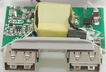
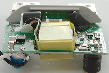
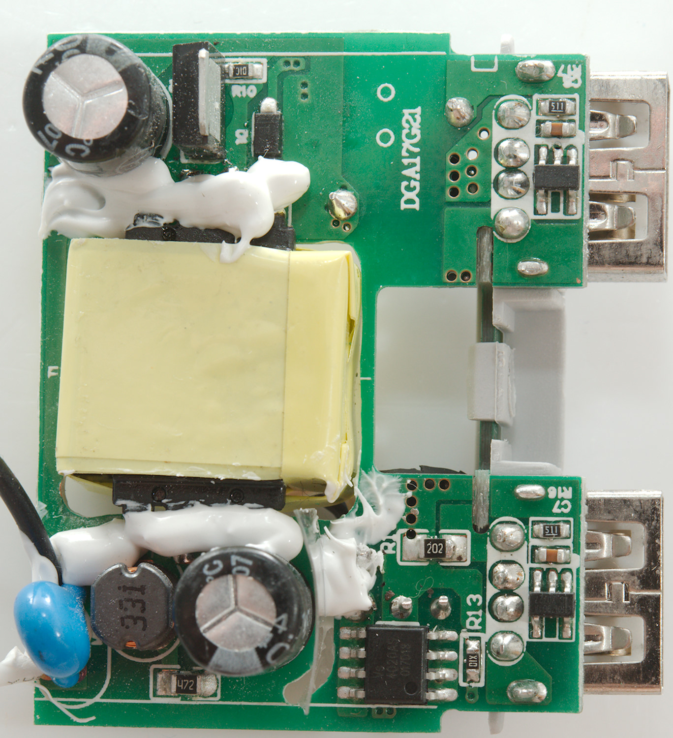
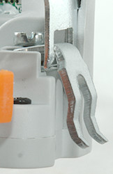
The distances are fairly small on this usb charger, to help a piece of plastic is glued into the slot.
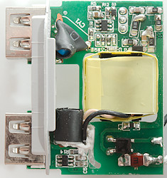
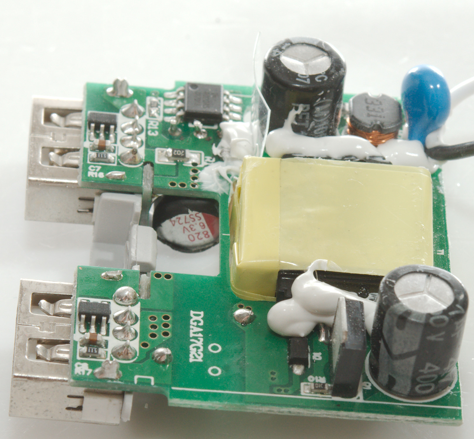
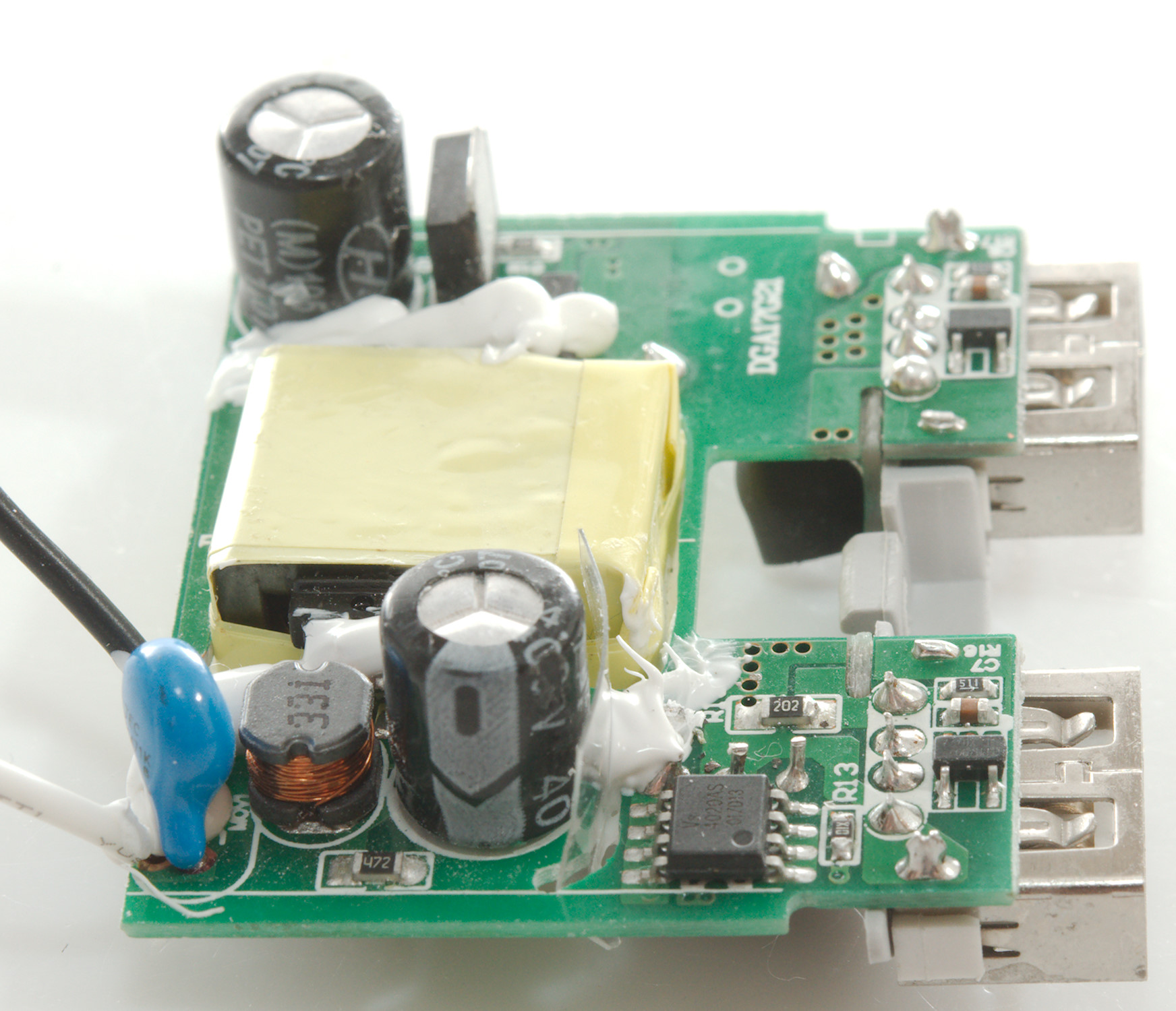
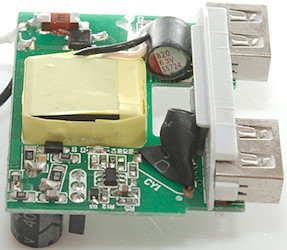
On this side is the fuse and bridge rectifier, there is also the switcher controller and a safety capacitor. On the low volt side is a synchronous rectifier controller chip next to the low volt smoothing capacitor.
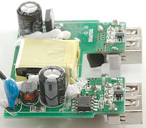
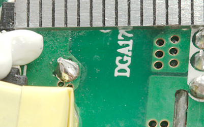
The distance across from the safety capacitor is about 6mm.
Testing with 2830 volt and 4242 volt between mains and low volt side, did not show any safety problems.
Conclusion
For a charger hidden in a mains outlet it is fairly powerful and it has auto coding. The safety do also looks fairly good. Because it is always connected it is also important with a low standby power and it lives up to that.
But it can only do one fast charge at a time.
Notes
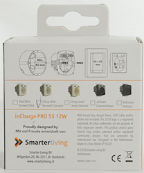
Charger was supplied by a smarterliving.nl for review.
Index of all tested USB power supplies/chargers
Read more about how I test USB power supplies/charger
How does a usb charger work?