3-Port USB 4.2A Car Charger with QC
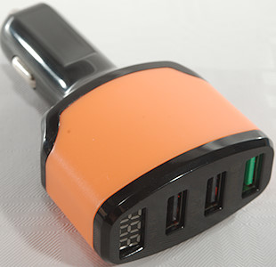
Official specifications:
- input: 12V-24V
- Frequency: 50-60Hz A car do not have any frequency
- the output voltage: 5V
- output current: 2400mA IC with protection scheme
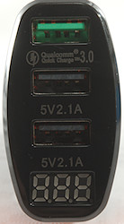
- the output interface: QC3.0 fast charge, three USB, with digital display
I got it from ebay dealer: xinyuancompany
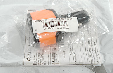
The charger was packed in a plastic bag inside an envelope, very common for Ebay.

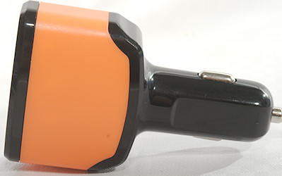
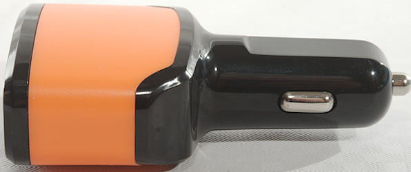
Measurements
- Regular USB outputs (2&3) is coded as USB charger (DCP)
- The two regular USB outputs are in parallel.
- QC USB output is coded as Apple 2.4A, Samsung, DCP, QC3, Samsung-AFC, Huawei-FCP
- Input voltage display will show lower voltage when output is loaded.
- Power consumption when idle is about 25mA on 12V and 33mA on 24V
- Minimum QC3 voltage: 3.7V
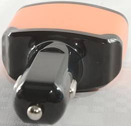
- Weight: 38.8g
- Length: 86mm
- Front: 51 x 29.9mm
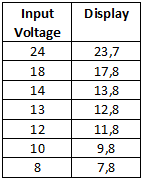
The voltage display shows battery voltage, but its on the low side and will go even lower when a output is used.
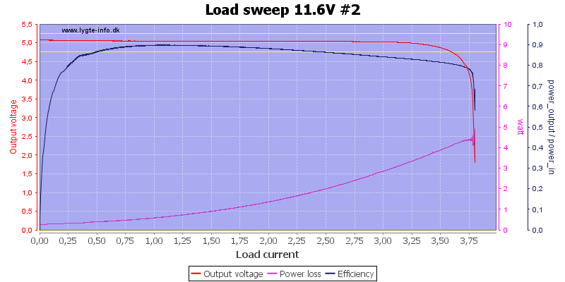
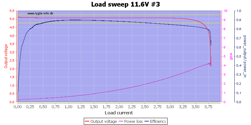
The first regular USB output can deliver about 3.5A
And the same with the second, they are in parallel and the total current is also 3.5A
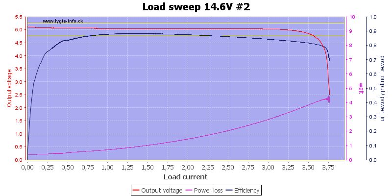
Higher input voltage do not change the current.
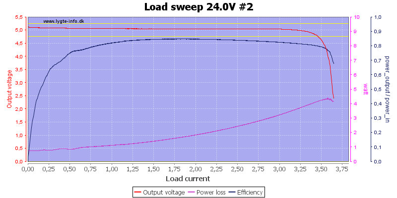
Even at 24V it is about the same.
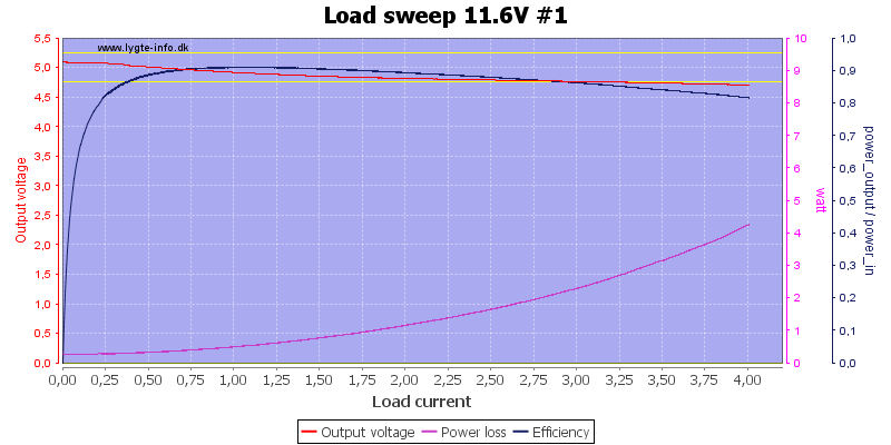
The QC output can deliver more than 4A.
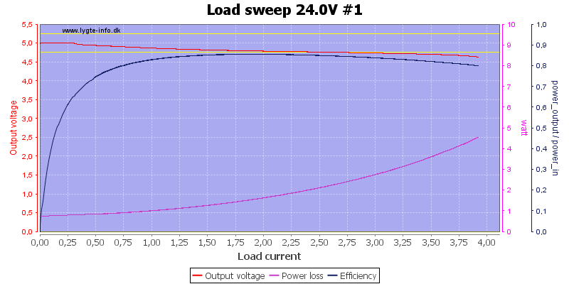
At 24V input it can deliver nearly 4A.
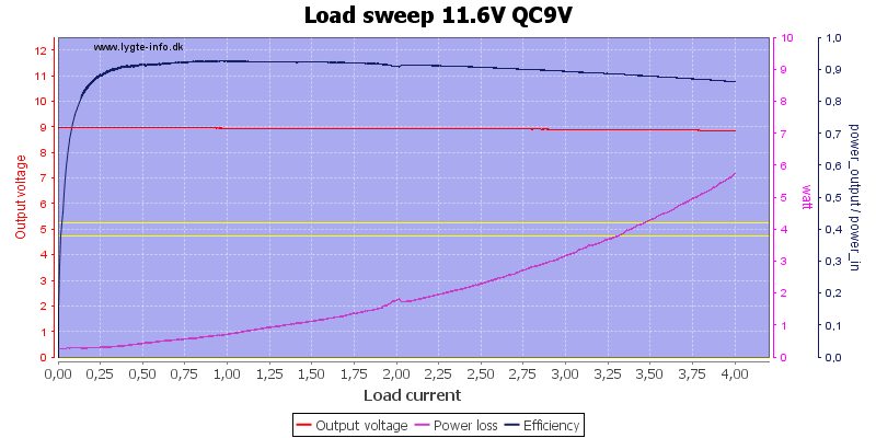
With 9V QC it is also more than 4A.
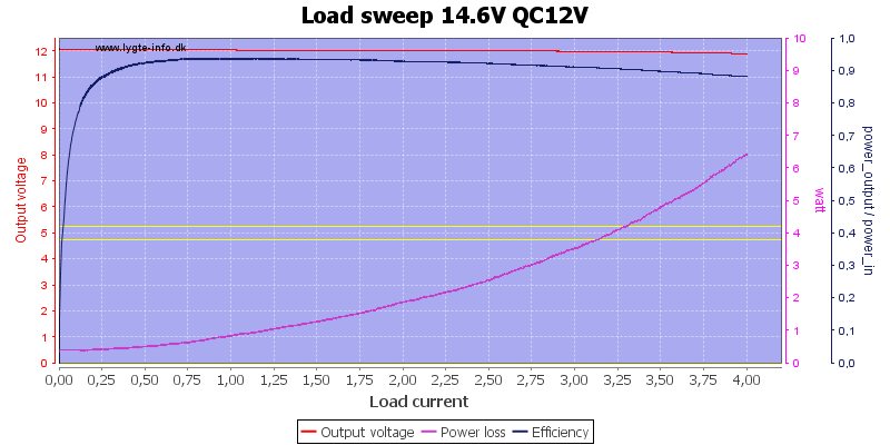
And also at 12V QC
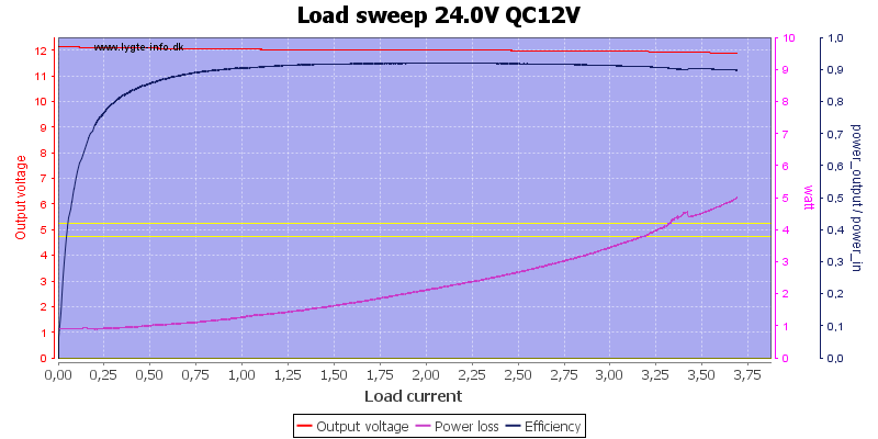
With 24V input the output current is limited to about 3.7A.
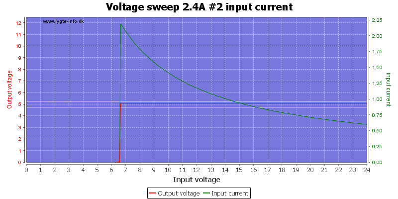
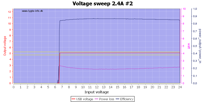
The regular USB outputs works down to about 7V input.
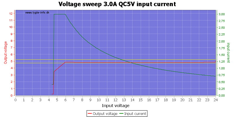
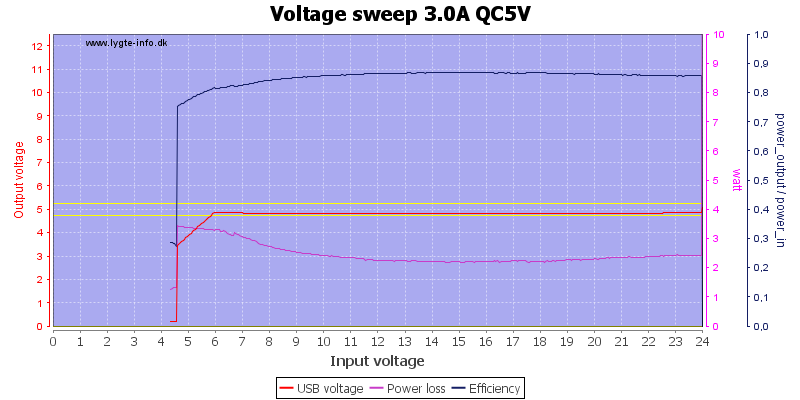
The QC input works down to about 6V with 5V output.
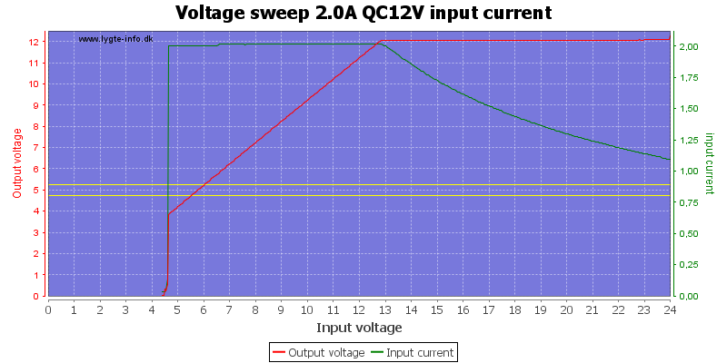
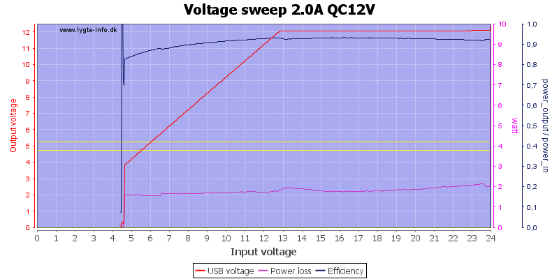
With 12V QC output only 13V is needed.
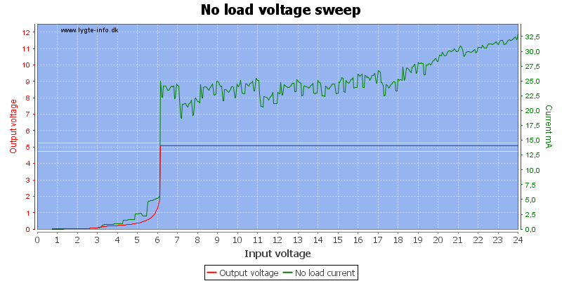
Current consumption varies a bit with input voltage and display reading.
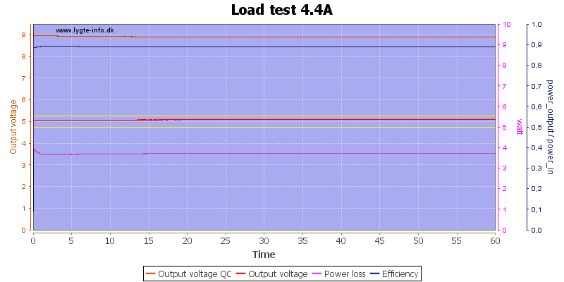
Without any real good specifications I decided to use 2.4A load for regular USB and 2A load on QC9V.
The temperature photos below are taken between 30 minutes and 60 minutes into the one hour test.
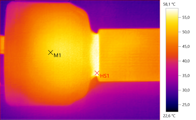
M1: 53.2°C, HS1: 58.1°C
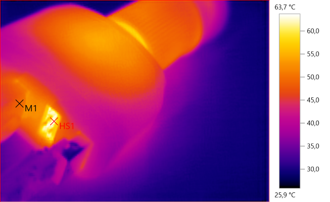
M1: 49.3°C, HS1: 63.7°C

Noise at 0.5A output is 45mV rms and 251mVpp

Noise at 1A output is 68mV rms and 375mVpp

Noise at 2.5A output is 68mV rms and 251mVpp
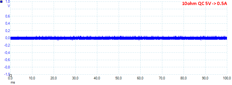
Noise at 0.5A output is 32mV rms and 115mVpp
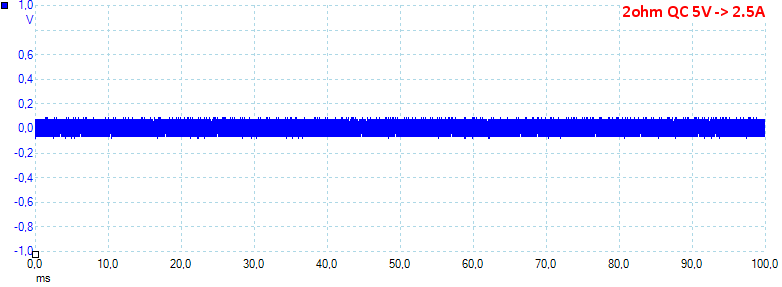
Noise at 2.5A output is 48mV rms and 186mVpp
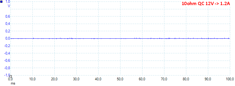
Noise at 1.2A output is 22mV rms and 99mVpp.
Tear down
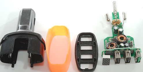
Mounting the front in my vice and I could break the back loose.
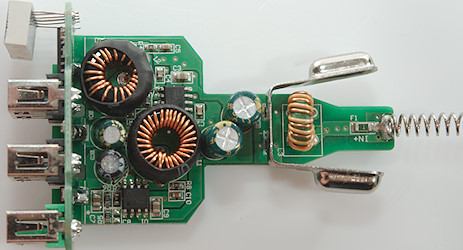
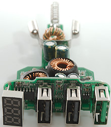
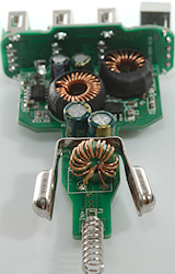
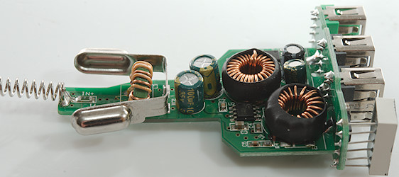
This charger has a common mode coil (L3) at the 12V input, this is very uncommon. There is also a fuse (F1).
The circuit has two switchers, a regular (U2: HC2006) and one for QC (U1: HC1002) with their inductors (L2 & L1) and smoothing capacitors (EC4 & EC3). The two input capacitors (EC1 & EC2) are in parallel.
Here is also the explanation on the voltage displays shows load dependency, it is connected after the common mode coil, i.e. it sees the voltage drop in the fuse, coil and spring.
The spring looks fairly solid.
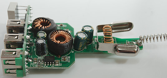
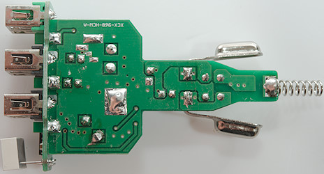
There is nothing on the other side of the circuit board.
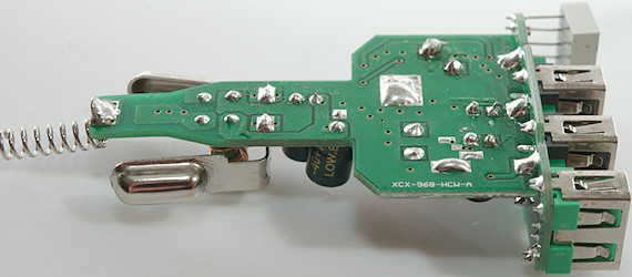
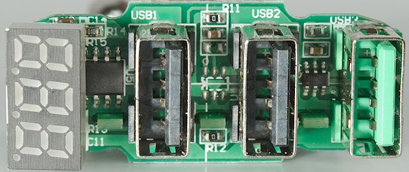
There is a few parts on the front, the QC controller (FT4), a empty space for a automatic protocol id and the unmarked voltmeter IC (U5)
Conclusion
For a cheap car charger is a fairly good, but I would have liked the missing protocol IC and better overload protection.
The voltmeter is not that useful due to the error.
Notes
Read more about how I test USB power supplies/charger
Compare car chargers and other DC supplied chargers


