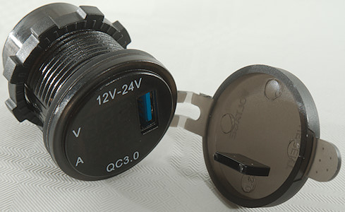
3A USB socket for 12V and 24V
Official specifications:
- Input Voltage: 12-24V
- Output: 5V/3A
- USB Port: 1
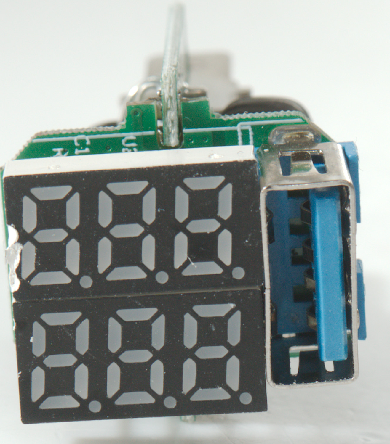
- Voltage Meter: Digital display
- Measuring Range: 6-36V
I got it from ebay dealer: huangjian1992
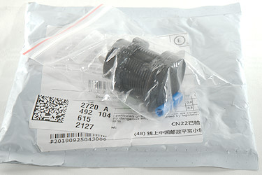
A plastic bag inside a plastic envelope, fairly standard packing for cheap stuff from Ebay.
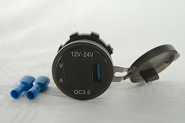
I got the charger and two spade terminals for connecting the wires.
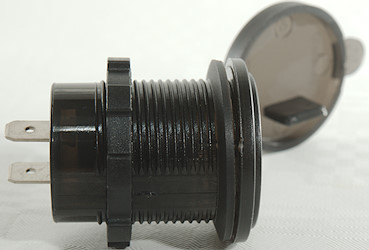
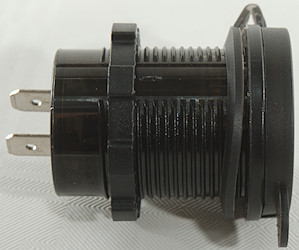
The charger is made to be mounted in a hole.
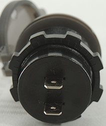
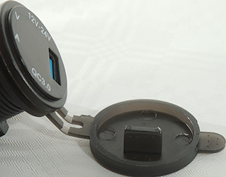
On the back is spade terminals for power input, the front has a lid.
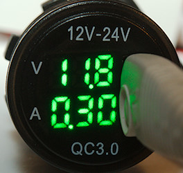
In addition to the USB output there is also a display showing the input voltage and the output current.
Measurements
- Power consumption when idle is 12mA from 12V
- Minimum QC3 voltage is 3.6V
- USB output is coded as: Apple 2.4A, DCP, QC3, Samsung-AFC, Huawei-FCP
- Weight: 26.0g
- Depth: 51.2mm with closed lid and including unconnected terminals on the bacl
- It will stick 9mm out from a panel and it can be mounted in a 19mm thick panel.
- Diameter: 28.4mm for mounting hole and 36.1mm for front.
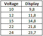
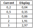
The volt and ammeter are not very precise.
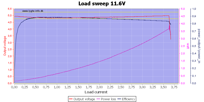
At 5V the charger can deliver about 3.7A.
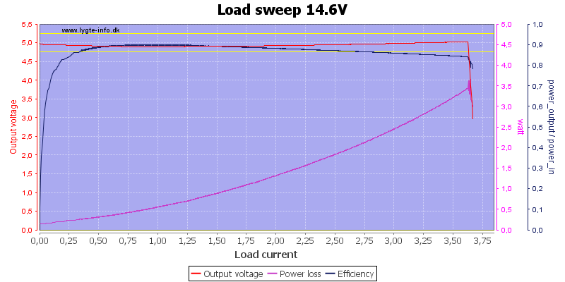

Input voltage do not matter, current is nearly the same at any voltage.
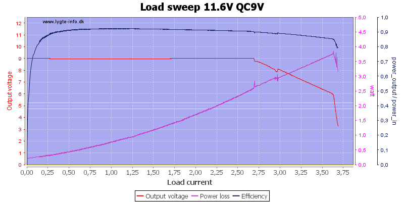
With QC 9V it can maintain output voltage up to 2.7A, then it starts dropping.
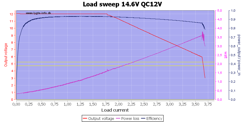
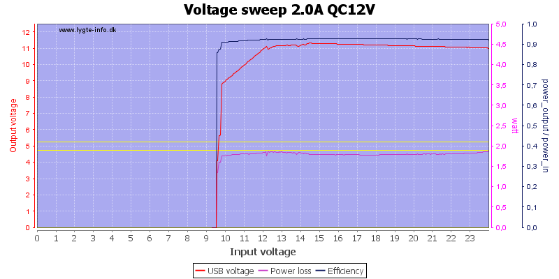
At 12V it can "only" maintain output voltage up to 1.7A
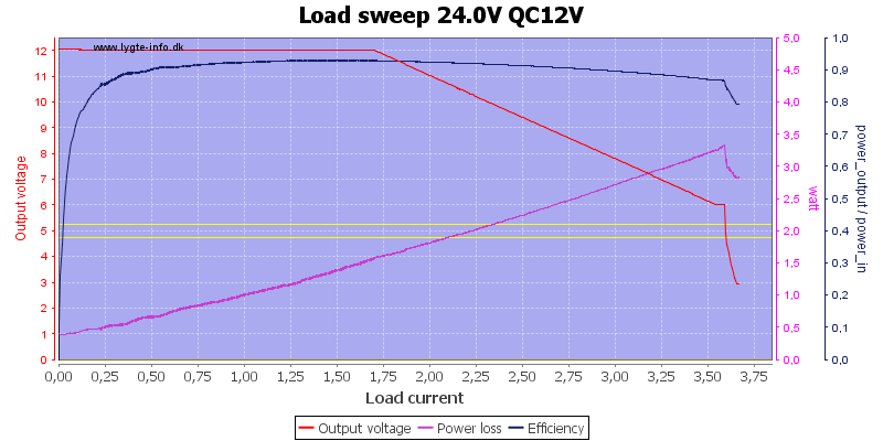
Higher input voltage do not change it.
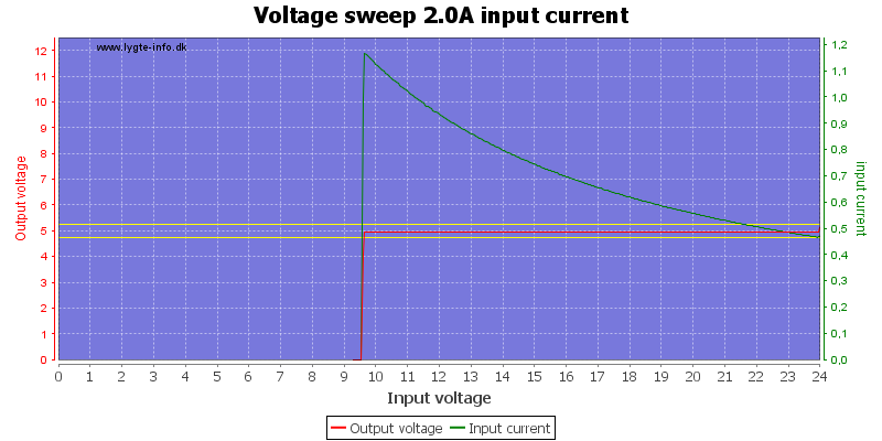
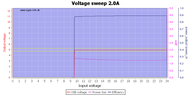
THe circuit has a cut-off at about 9.5V input voltage.
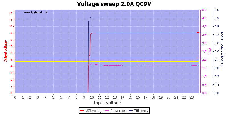
The cut-off voltage do not change when QC is activated.
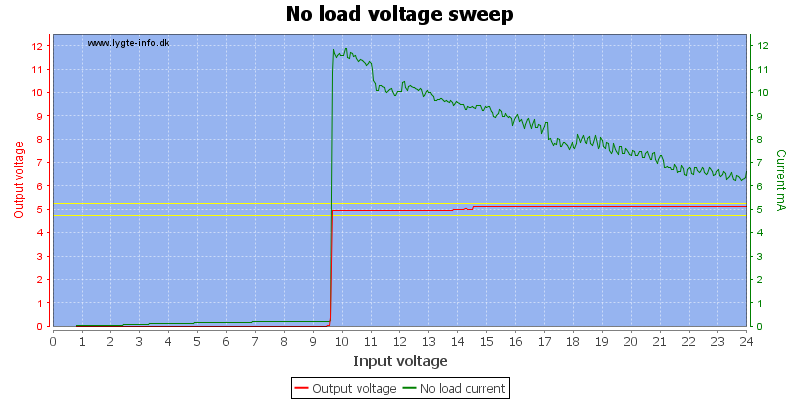
The chargers current consumption depends on the input voltage and slightly on the display.
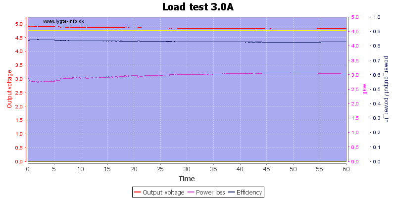
Running with 3A and 5V output for one hour worked fine.
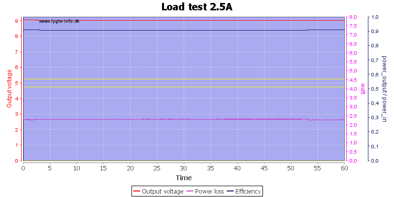
I could also run with 9V output and 2.5A for a hour.
The temperature photos below are taken between 30 minutes and 60 minutes into the one hour test.
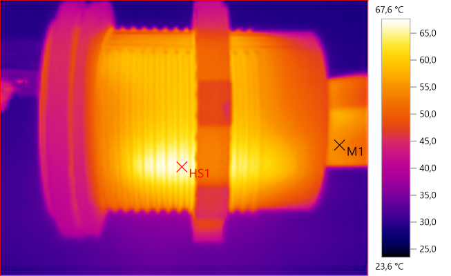
M1: 54.0°C, HS1: 67.6°C
This photo and the one below is from the 5V 3A test.
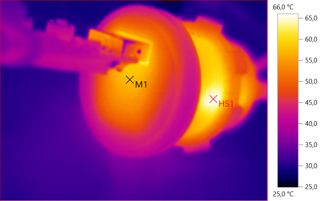
M1: 57.7°C, HS1: 66.0°C
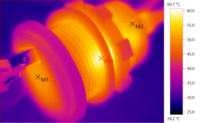
M1: 50.5°C, M2: 50.1°C, HS1: 60.7°C
Here is a photo from the 9V 2.5A test.
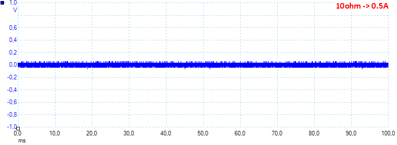
At 0.5A the noise is 32mV rms and 163mVpp.
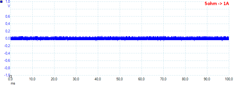
At 1.0A the noise is 30mV rms and 134mVpp.
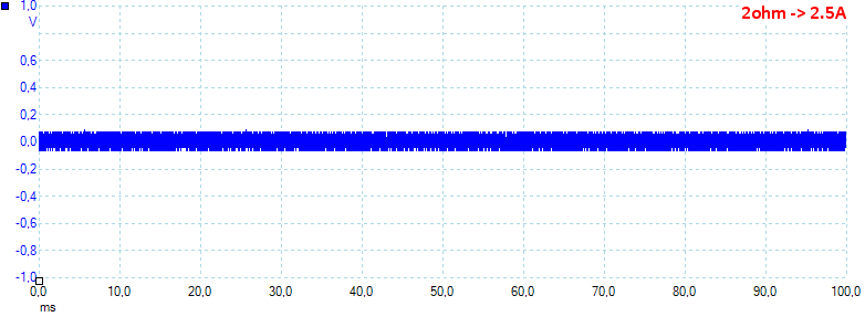
At 2.5A the noise is 40mV rms and 280mVpp.
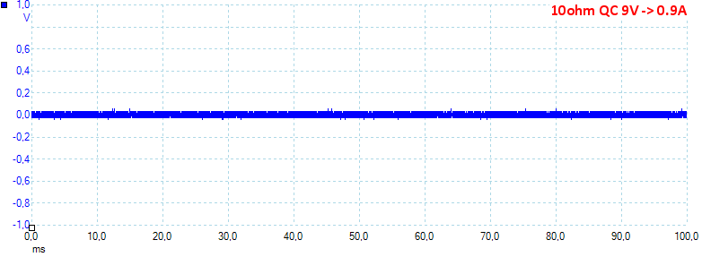
At 0.9A and 9V the noise is 22mV rms and 120mVpp.
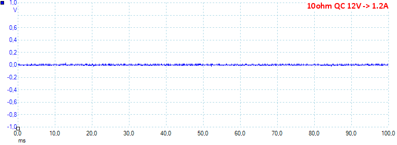
At 1.2A and 12V the noise is 4mV rms and 62mVpp.
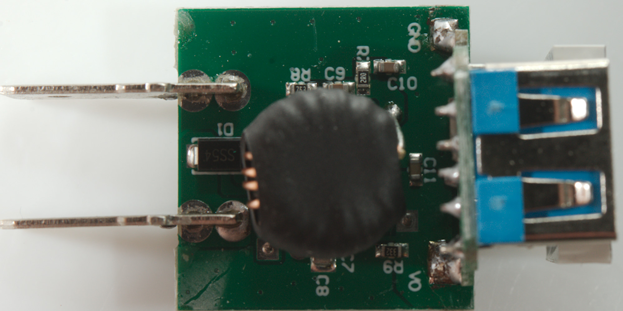
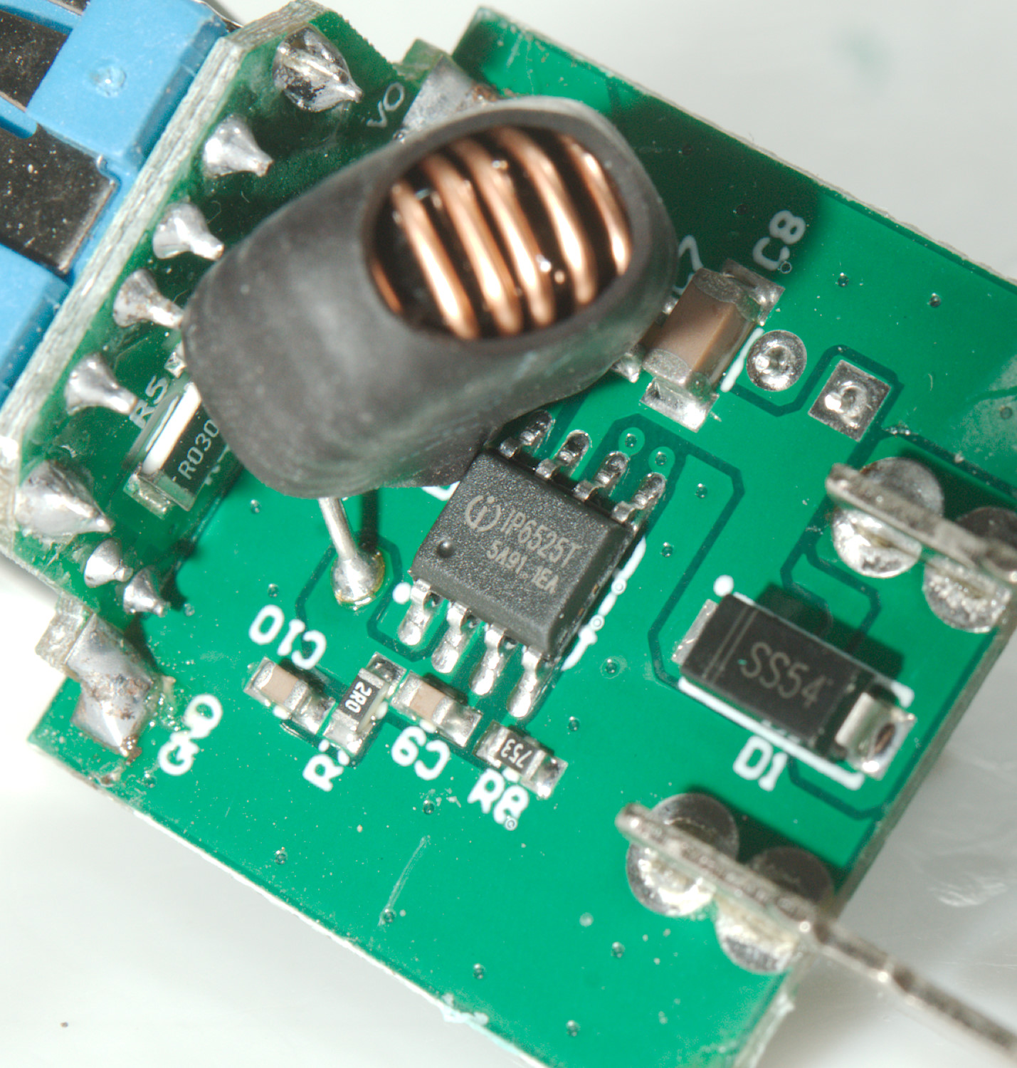
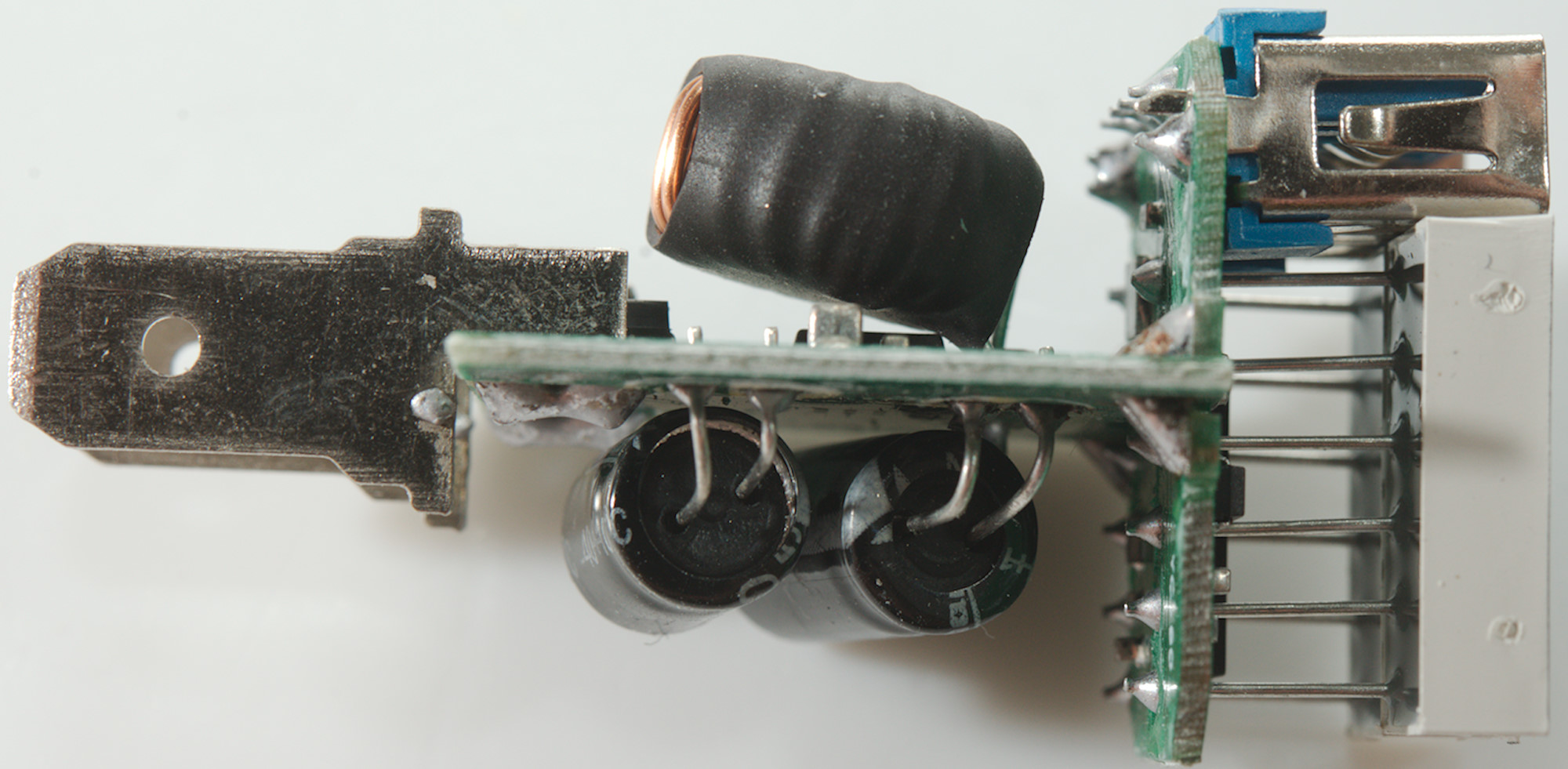
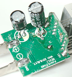
Tear down
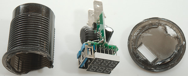
It was a bit difficult to break open.


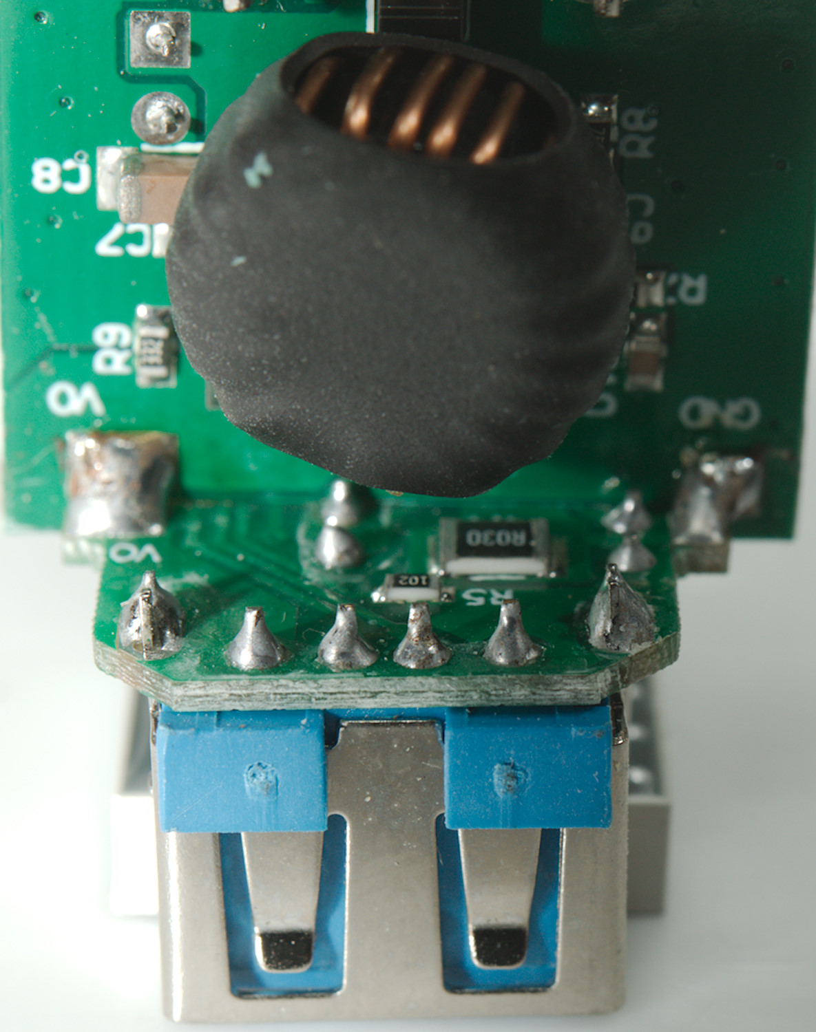
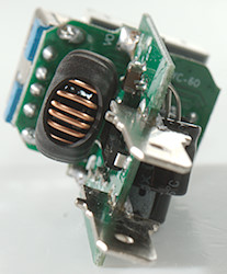
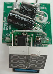
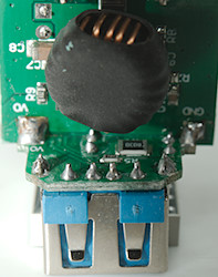
There is one combined switcher and QC chip below the inductor. There is a diode in series with the input, i.e. it is protected against wrong polarity on the input terminals.

Typical schematic from the datasheet.
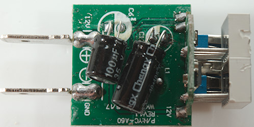
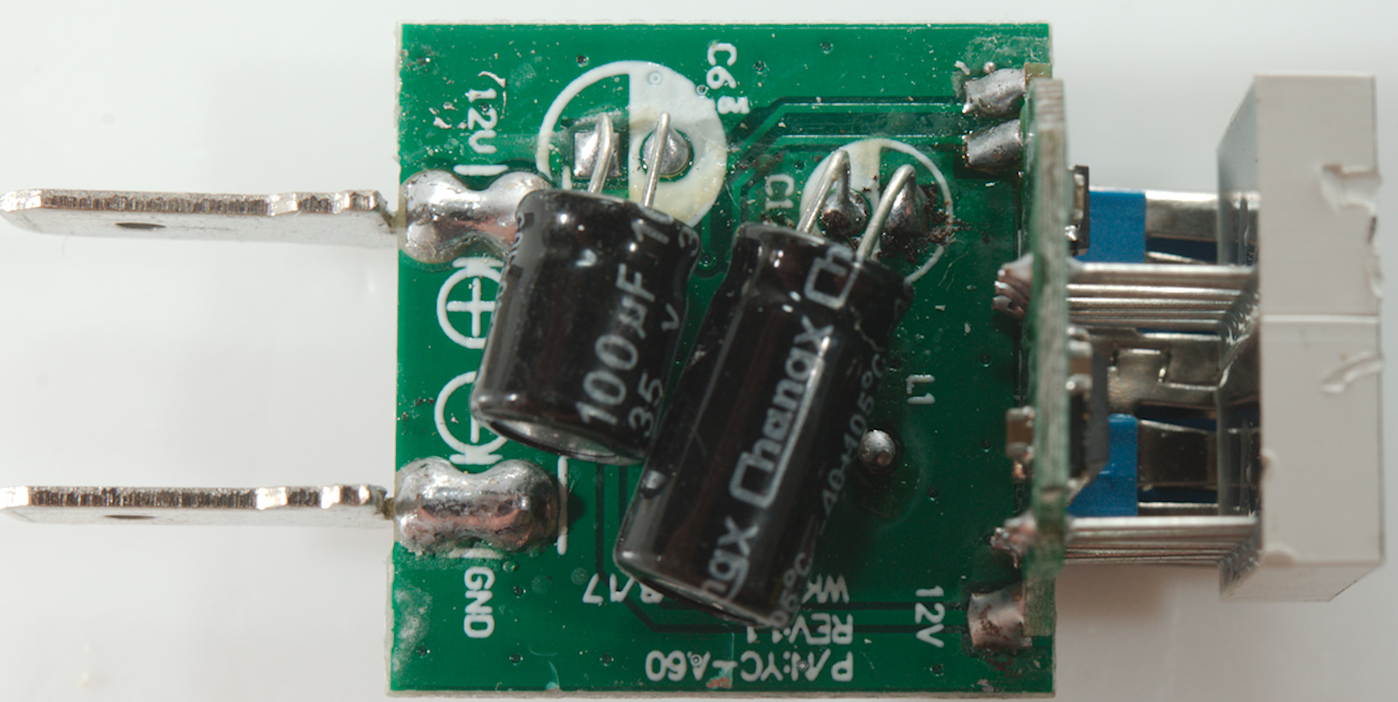
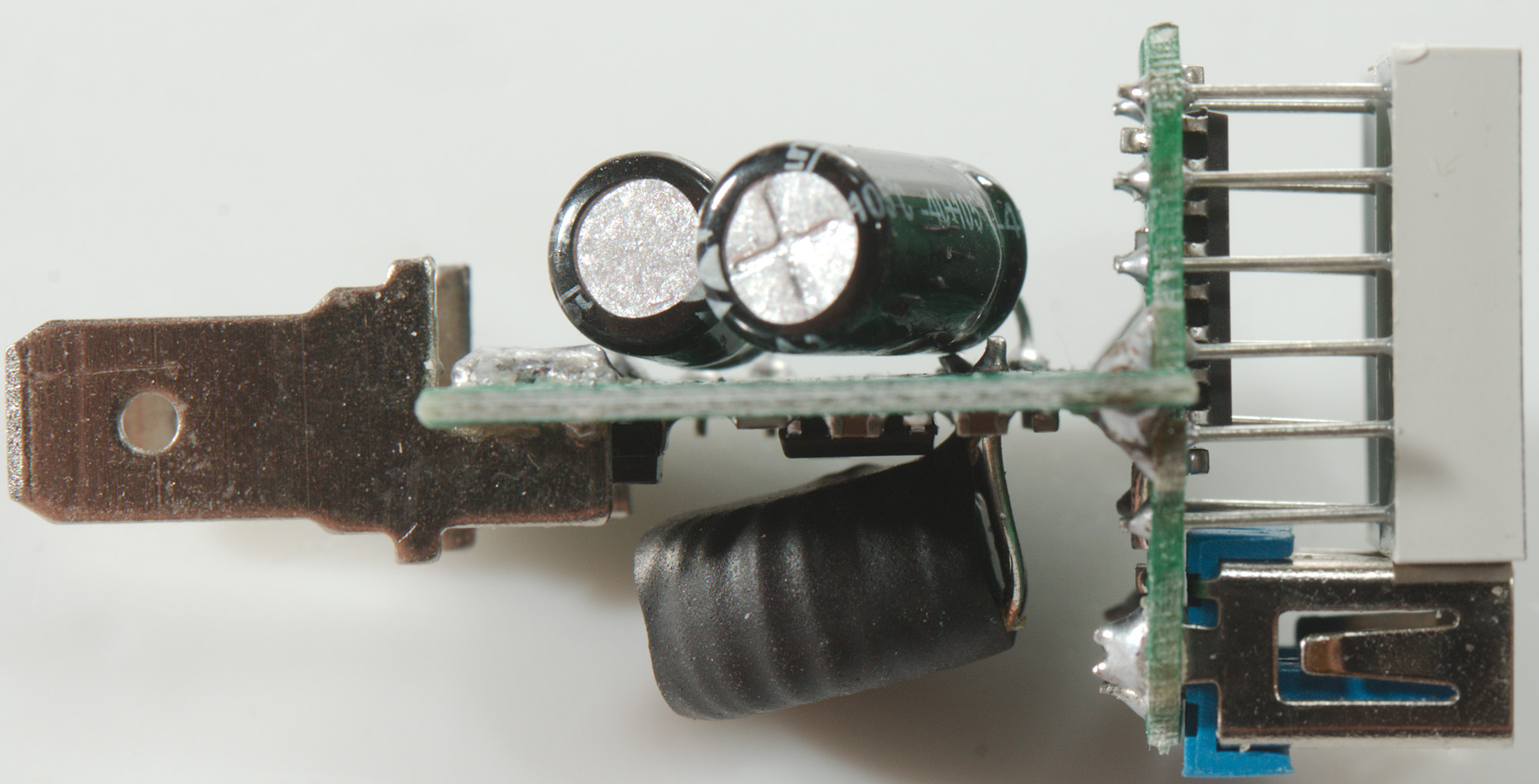
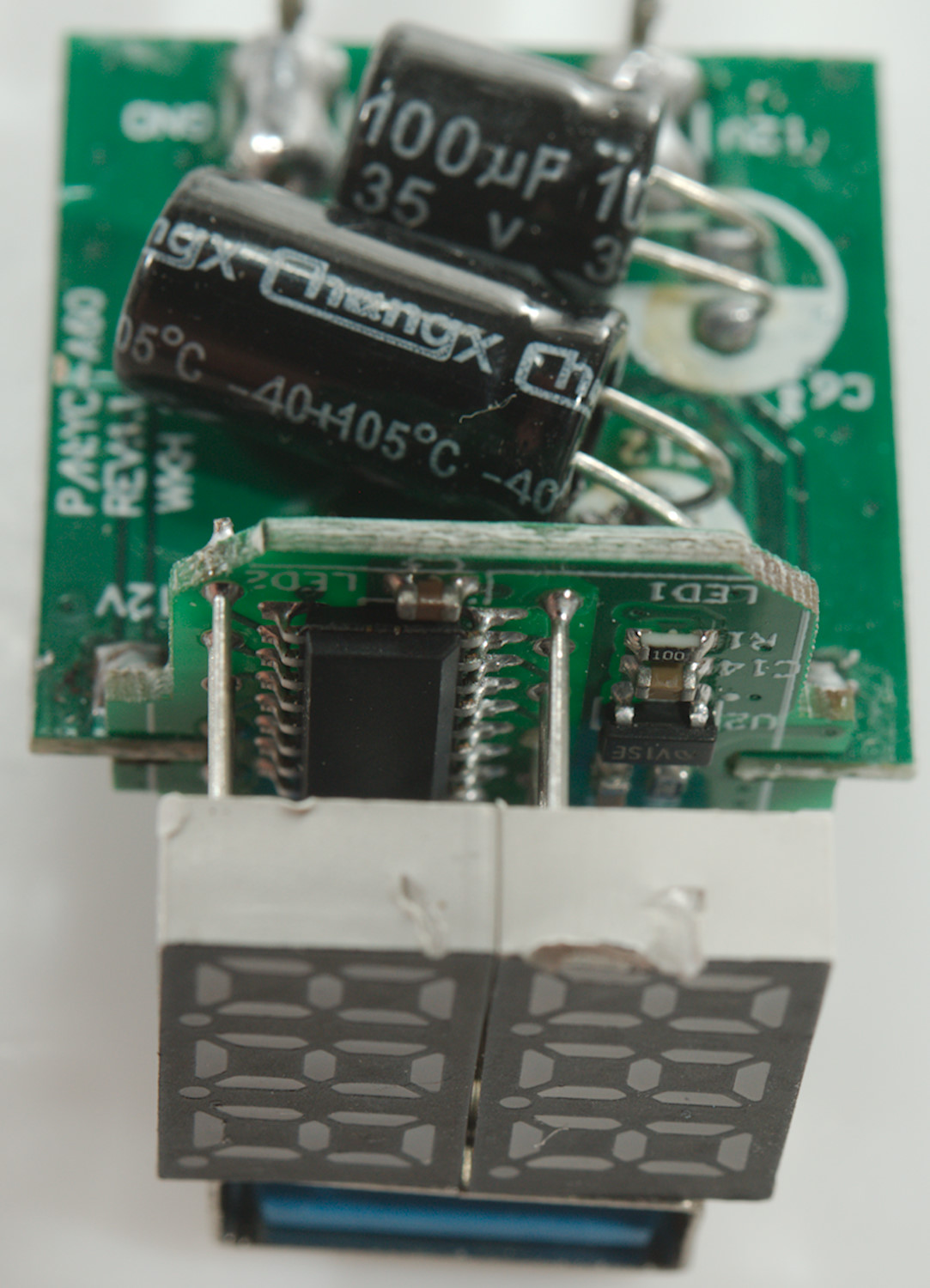
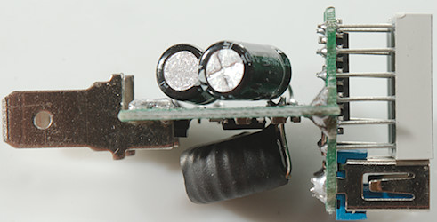
On the other side of the circuit board is the input and output capacitors.
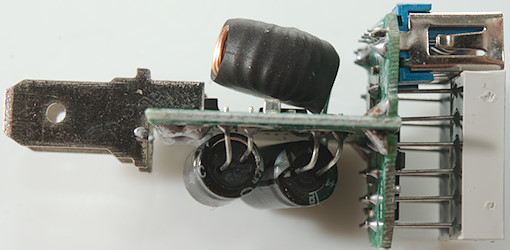
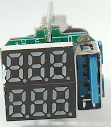
Behind the display is the V&A meter chip, a voltage regulator and a sense resistor.
Being a 12V device there is no need to test with high voltages.
Conclusion
Even though it is a fairly cheap USB charger, I will call it a good one, the used chip supports a couple of codings, it has overload protection and acceptable noise.
Notes
Read more about how I test USB power supplies/charger
Compare car chargers and other DC supplied chargers