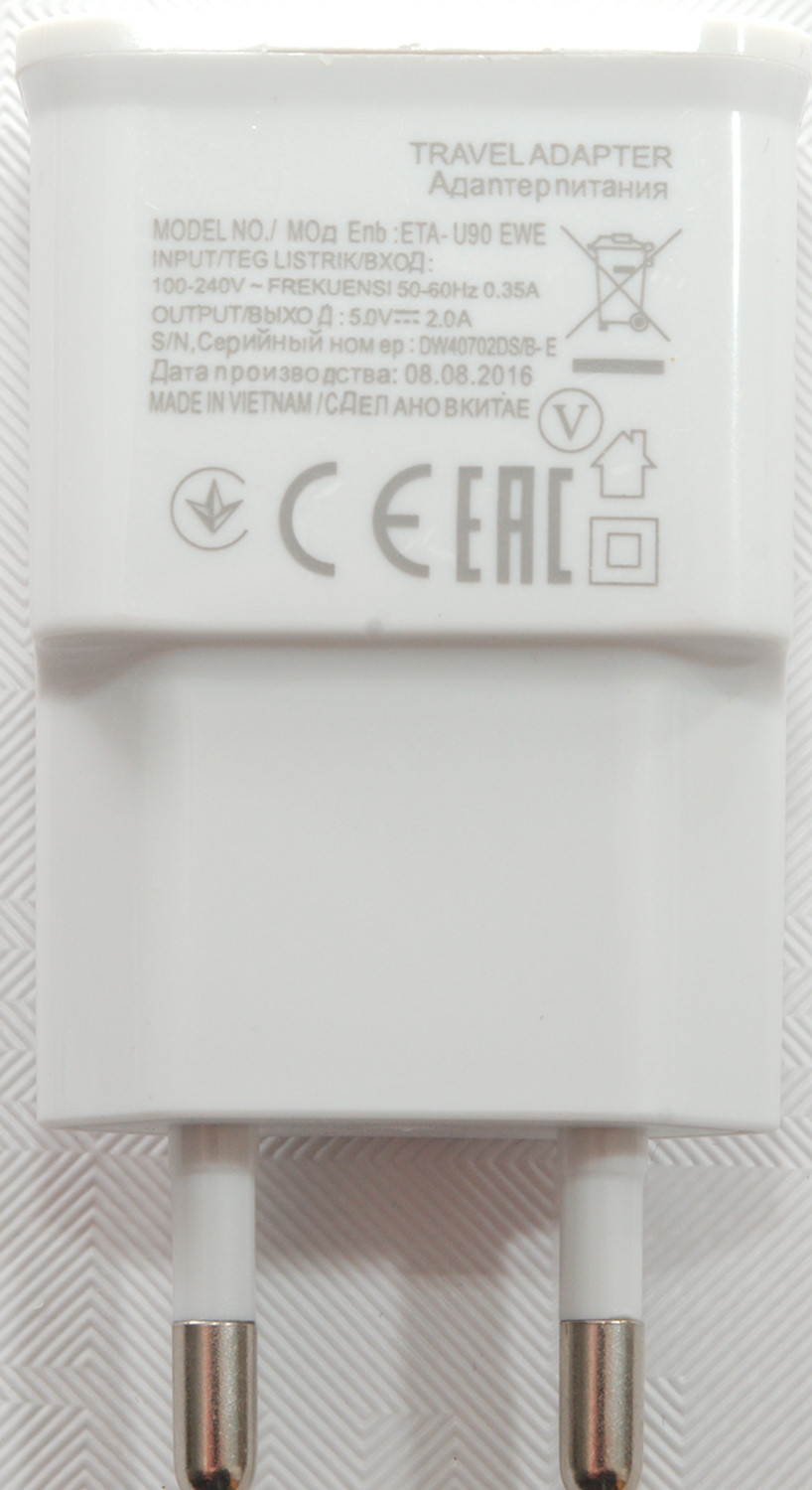
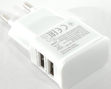
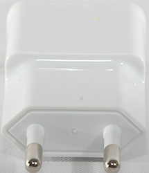
5V 2A Dual plug fast charger ETA-U90 EWE
Official specifications:
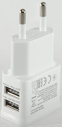
- Color: White
- Net Weight: 22g
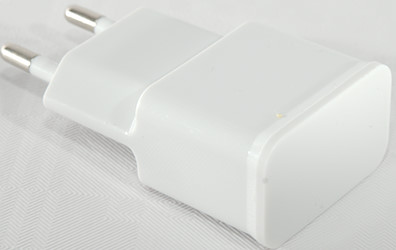
- Plug Type: EU Plug
- Output: DC 5V 2A(Max)
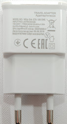
- Input: AC100-240V,50-60Hz, 0.35A
- Dimension: Approx.6.8(L) x 3.7(W) x 2.2(H)cm
I got it from ebay dealer ctstore-ca

This cheap charger arrived in envelope.
Measurements
- Power consumption when idle is 0.09 watt
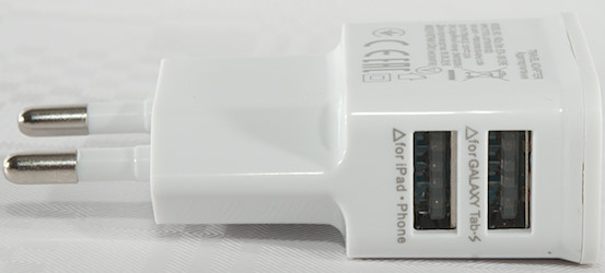
- Top usb output is coded as usb charger (DCP)
- Bottom usb output is coded as Apple 1A
- Both USB outputs are in parallel
- Weight: 23.2g
- Size: 68 x 37.2 x 22.3mm
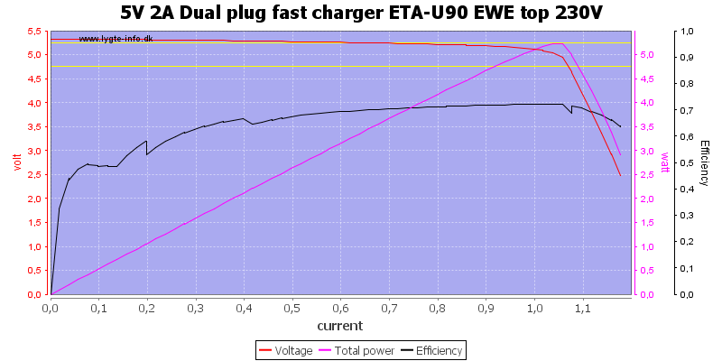
The charger can deliver about 1A before over current protection kicks in, not very good for a 2A charger.
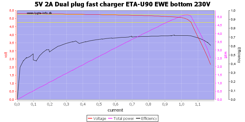
And the bottom connection is exactly the same.
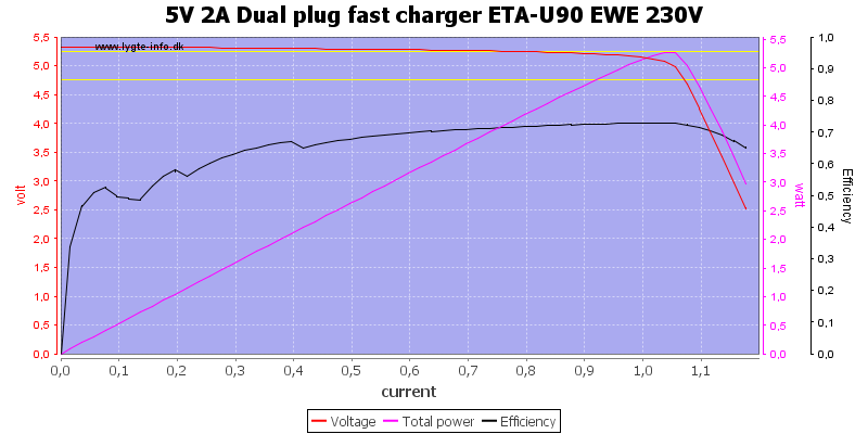
Using both outputs do not increase current.
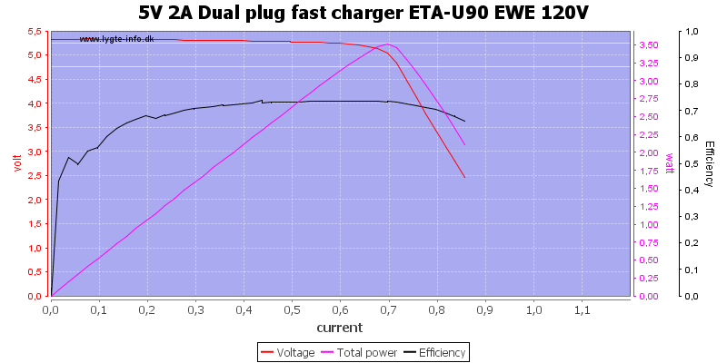
At 120VAC the output current is reduced to 0.7A.
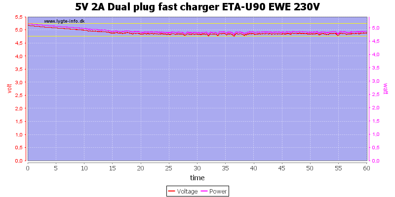
Running the charger with 1A total output worked, but voltage dropped when it heated up and there is some noise in the voltage.
The temperature photos below are taken between 30 minutes and 60 minutes into the one hour test.
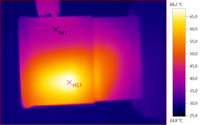
M1: 40.0°C, HS1: 68.2°C
HS1 is the switcher transistor.
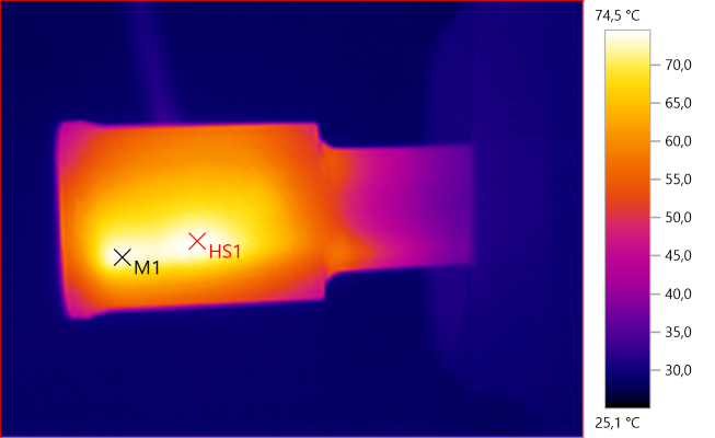
M1: 73.9°C, HS1: 74.5°C
M1 is the rectifier diode and HS1 the probably the snubber network.
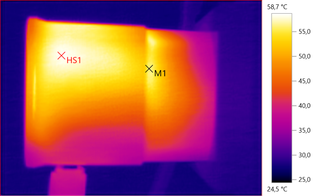
M1: 56.2°C, HS1: 58.7°C
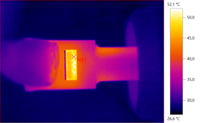
HS1: 52.1°C
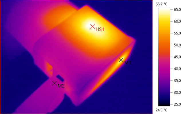
M1: 63.9°C, M2: 38.6°C, HS1: 65.7°C
HS1 is the switcher transistor, M1 is the rectifier diode.
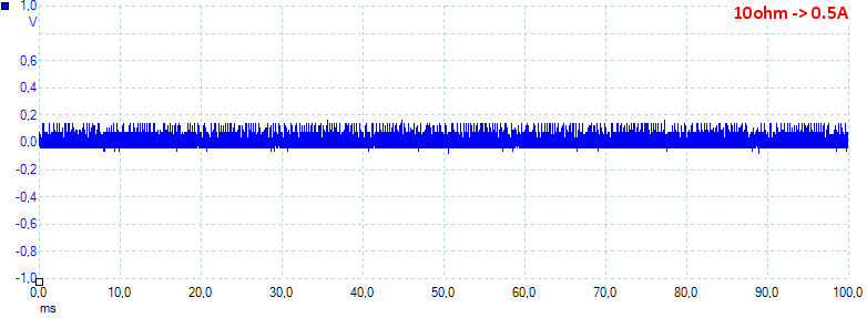
At 0.5A the noise is 49mV rms and 233mVpp. The noise is low here.
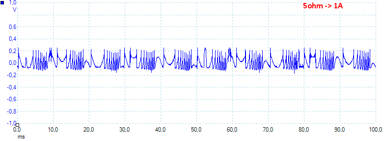
At 1A the noise is 87mV rms and 463mVpp. Here the output voltage does strange things.
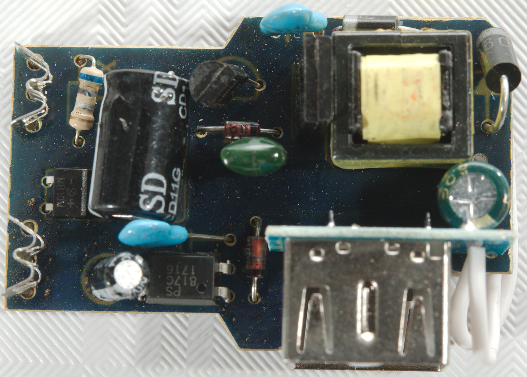
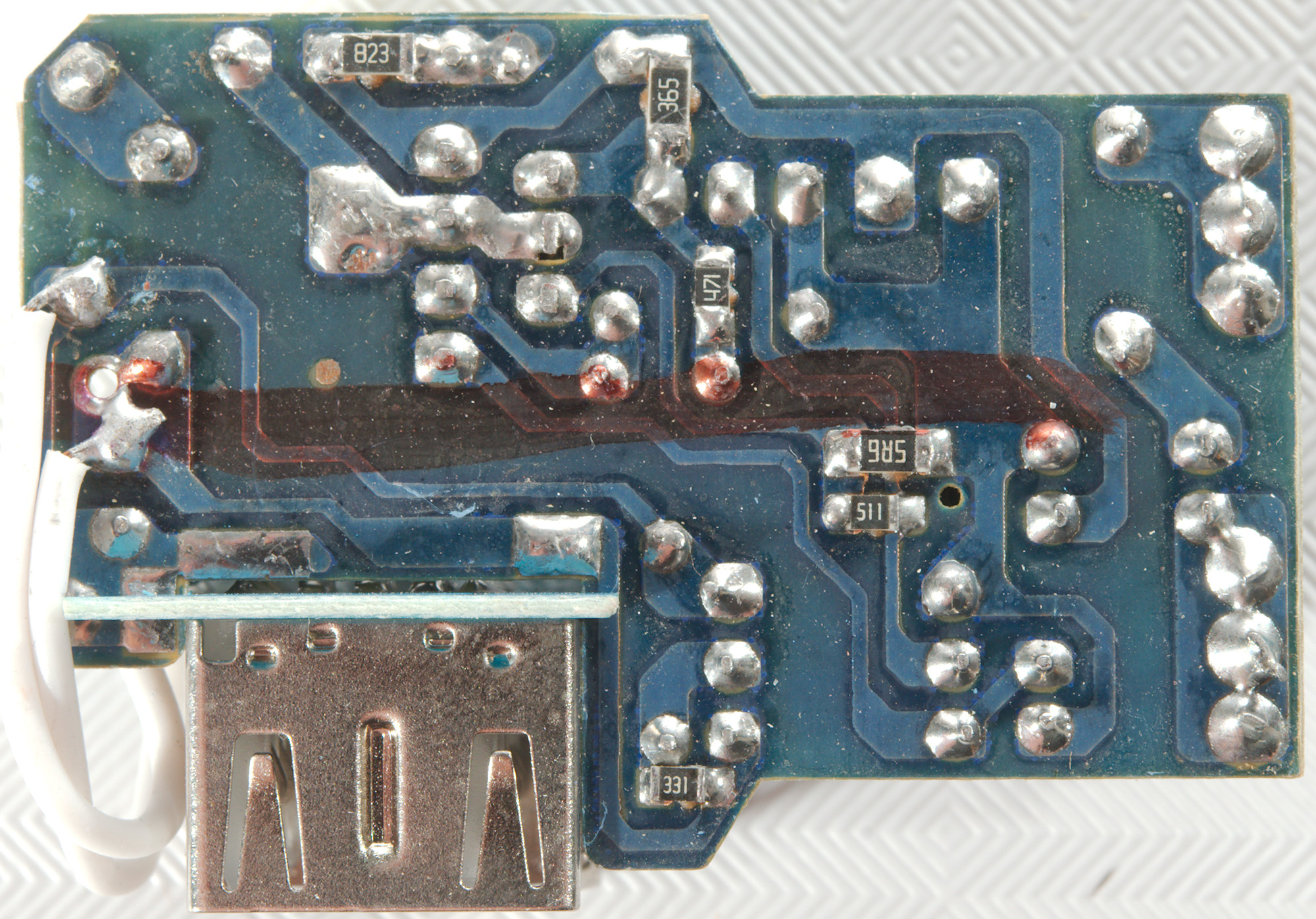
Tear down
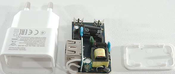
Some pressure with my vice and the lid popped off.
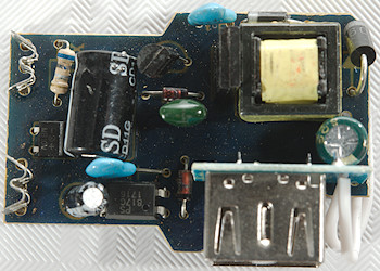
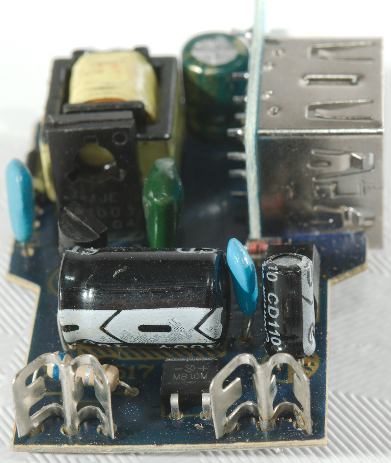
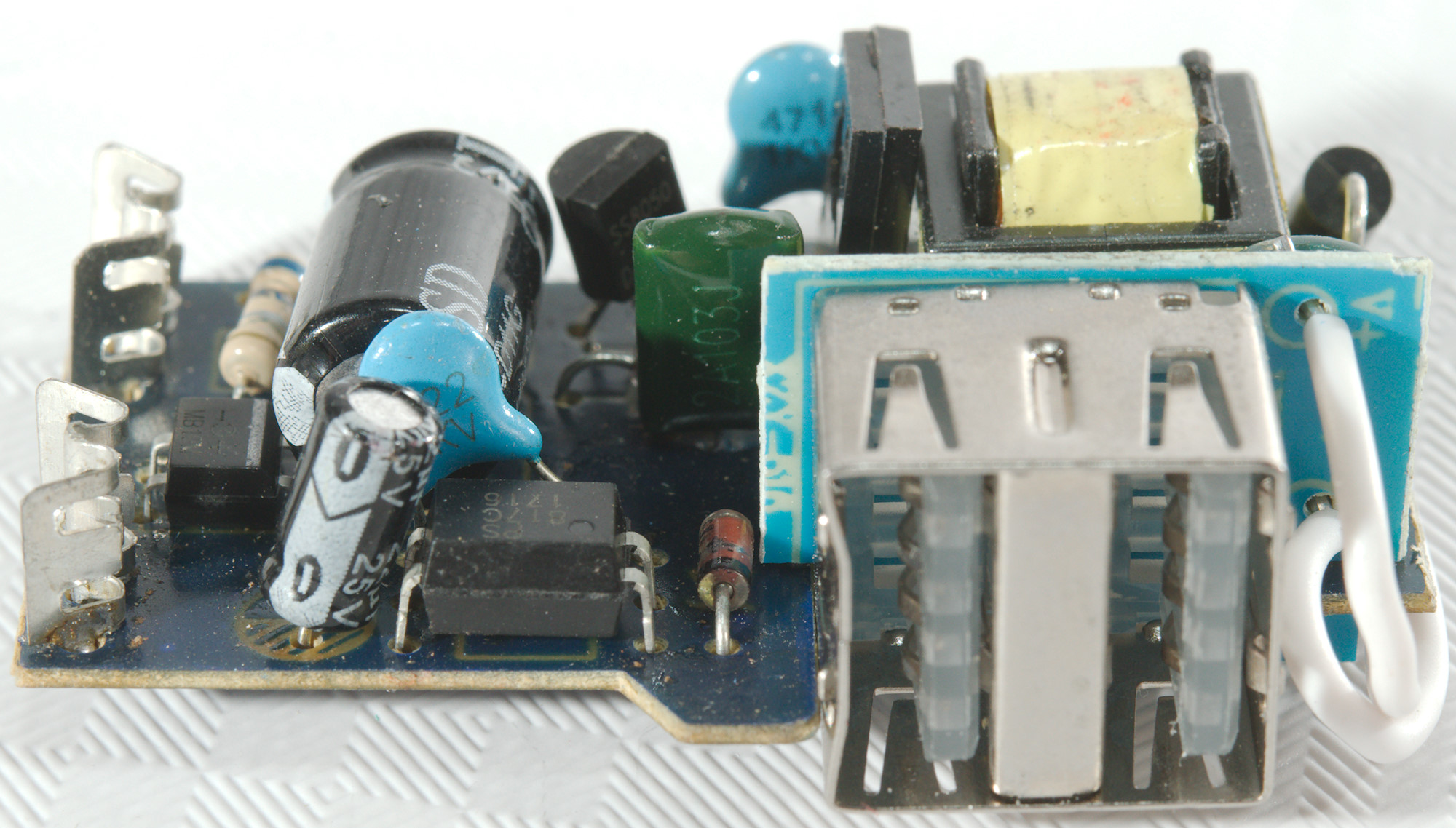
This is a real simple circuit, at the input is a resistor instead of a fuse, there is a bridge rectifier. The switcher is two transistors instead of a IC.
Between mains and low volt side is the opto coupler with a fake safety capacitor across (1KV type).
On the low volt side is a rectifier diode and instead of a reference chip is a zener diode (That is the reason the voltage drops when it gets hot).
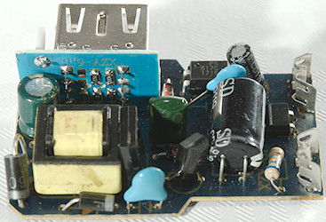
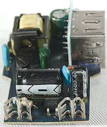

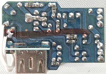
This side has a couple of small SMD resistors.
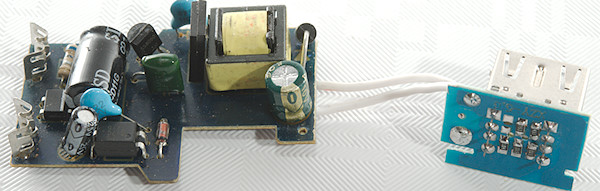
The two circuit boards are not soldered together.
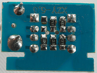
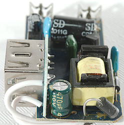
The usb coding resistors are on the usb connector board.
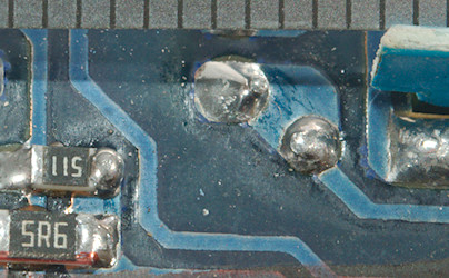
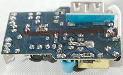
Distance between mains and low volt side must be above 6mm, it is around 2mm here.
The charger failed the 2830 volt and the 4242 volt test between mains and low volt side, this makes it unsafe anywhere in the world.
Conclusion
This charger has bad performance and is in the death trap category, stay away.
Notes
The charger was supplied by a reader for review.
Index of all tested USB power supplies/chargers
Read more about how I test USB power supplies/charger
How does a usb charger work?