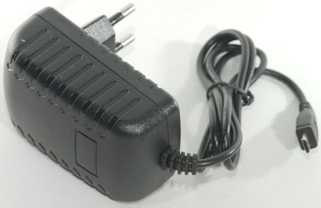
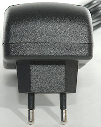
5V 3A usb power supply for Rasberry DSM-0530
Official specifications:
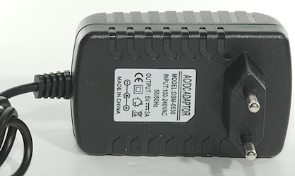
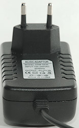
- Input: 100V-240V 50/60Hz
- Output: DC 5V 3A / 3000mA 15W
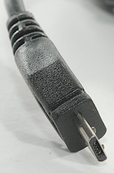
- Output adaptor jack size: MICRO USB
It is from ebay dealer: prizeshop
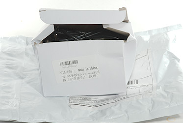
I got it in a envelope, it did not include any box or instruction sheets.
Measurements
- Power consumption when idle os 0.2 watt
- Usb output is coded as usb charger (DCP)
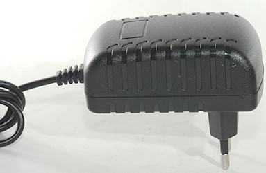
- Weight: 95.6g
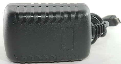
- Size: 90 x 68 x 50mm
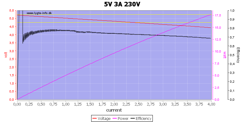
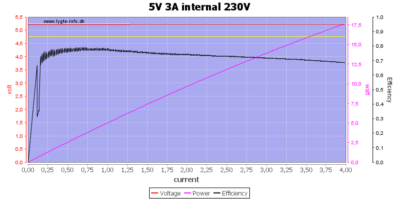
The voltage drops with load, this is due to the cable. The overload protection kicks in at 4A.
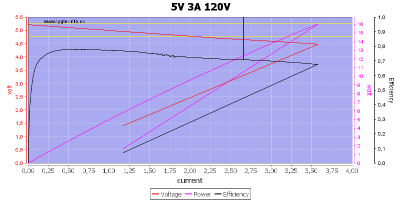
At 120VAC the overload kicks in at 3.5A
Just to prove a point I moved the voltmeter from the usb connector to the circuit board, i.e. this time there is no cable and no connector, this means no voltage drop.
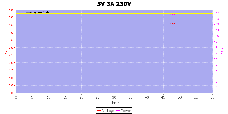
No obvious problems running one hour at 3A, but see below.
The temperature photos below are taken between 30 minutes and 60 minutes into the one hour test.
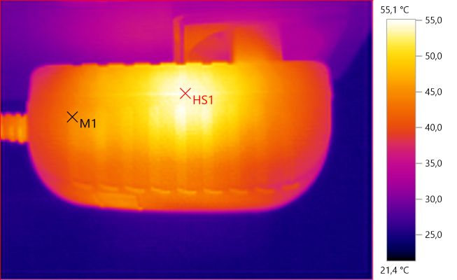
M1: 44,5°C, HS1: 55,1°C
HS1 must be the switcher.
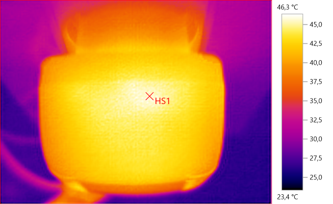
HS1: 46,3°C
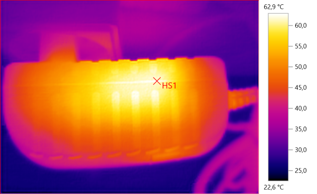
HS1: 62,9°C
HS1 is transformer and diode.
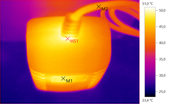
M1: 48,4°C, M2: 43,2°C, HS1: 51,0°C
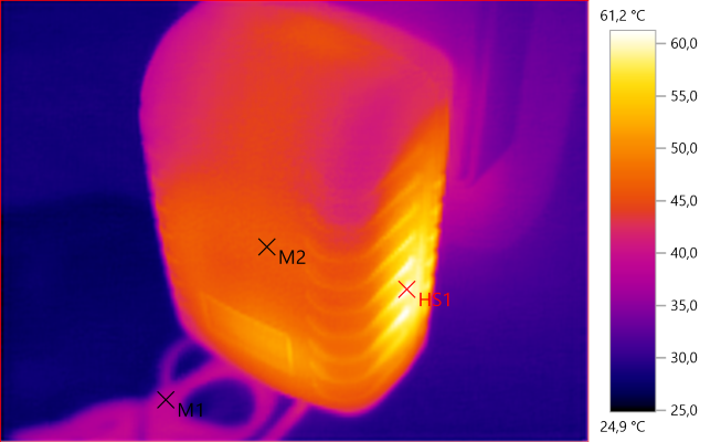
M1: 38,6°C, M2: 46,1°C, HS1: 61,2°C
HS1 is transformer and diode.
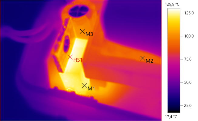
M1: 122,2°C, M2: 92,9°C, M3: 100,6°C, HS1: 129,9°C
With the strange looking circuit board below the rectifier diode, I did a test with the power supply open (This was only about 20 minutes after load was applied).
The rectifier diode needs a heatsink and it would be a good idea to relocate the capacitor next to it.
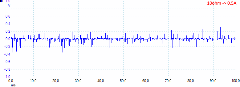
At 0.5A the noise is 24mV rms and 900mVpp.
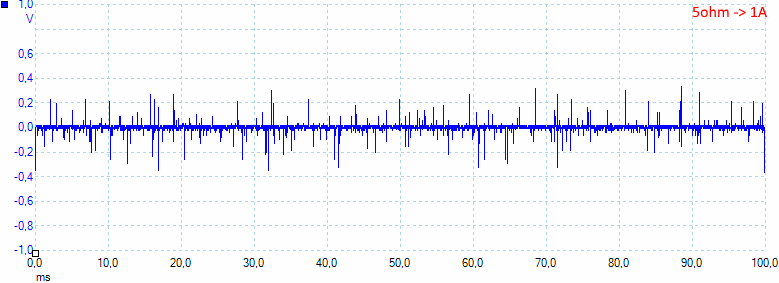
At 1A the noise is 30mV rms and 860mVpp.
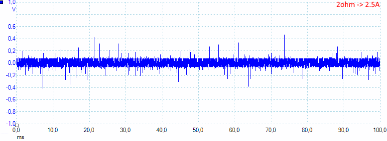
At 2.5A the noise is 57mV rms and 1100mVpp.
Tear down
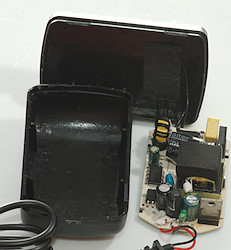
The power supply was hold together with clips, they held rather well together, but a spudger could pry it open.

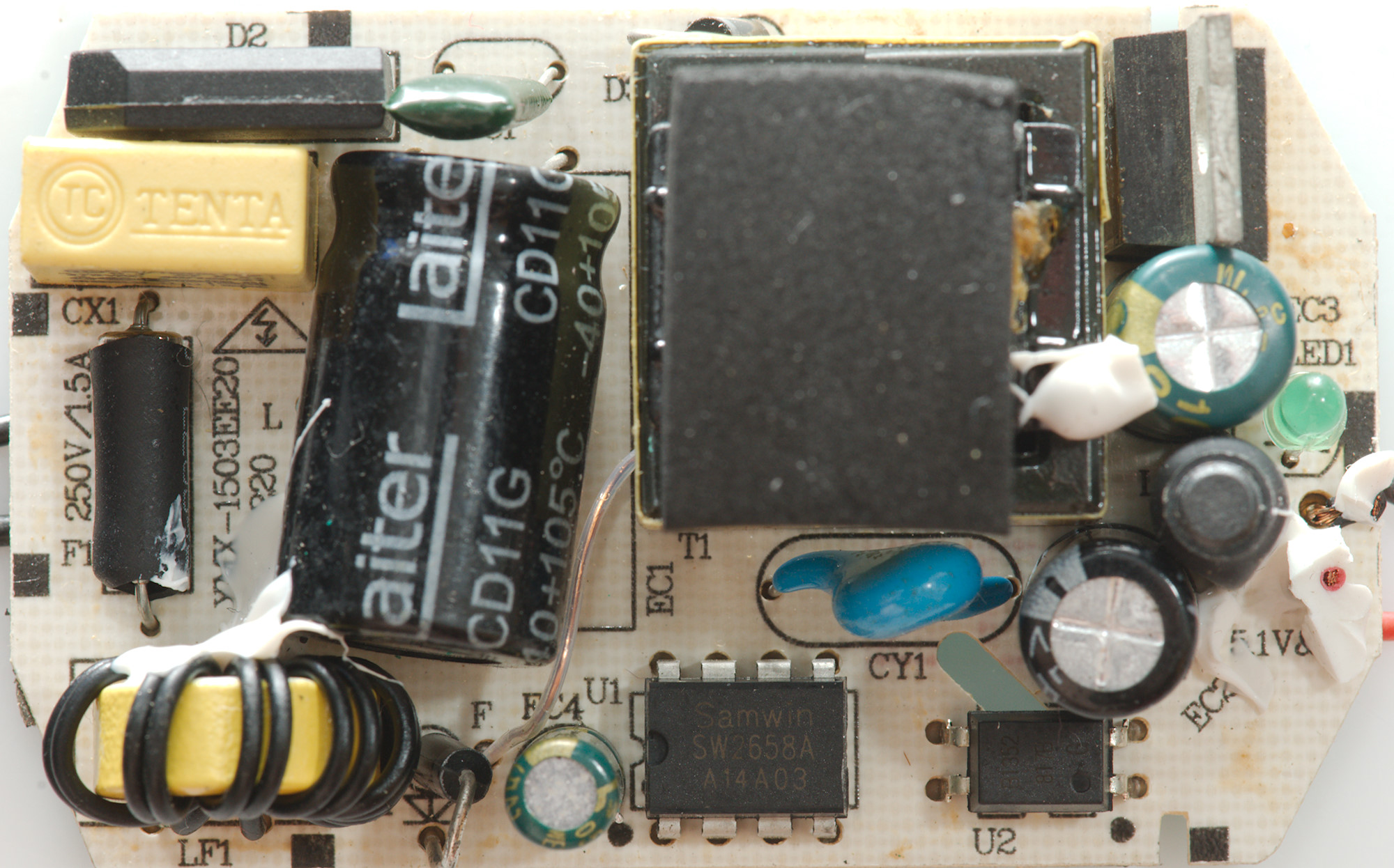
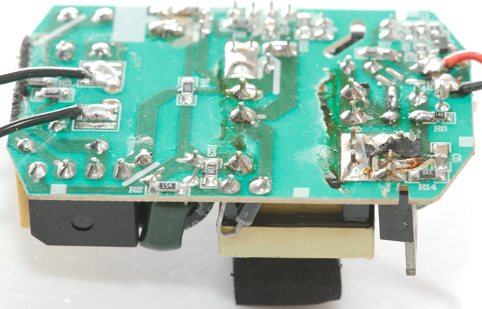
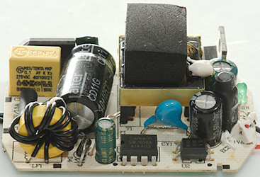
At the mains input is a fuse (F1:1.5A), a common mode coil (LF1), and a bridge rectifier (D2). The switcher is placed beside the transformer (U1:SW2658A). Notice the transformer has a flying lead with power for the switcher.
There is also a safety capacitor (CY1) and a opto coupler (U2).
On the low volt side is a rectifier diode, a inductor and a led (LED1), that led cannot be seen from outside the box.
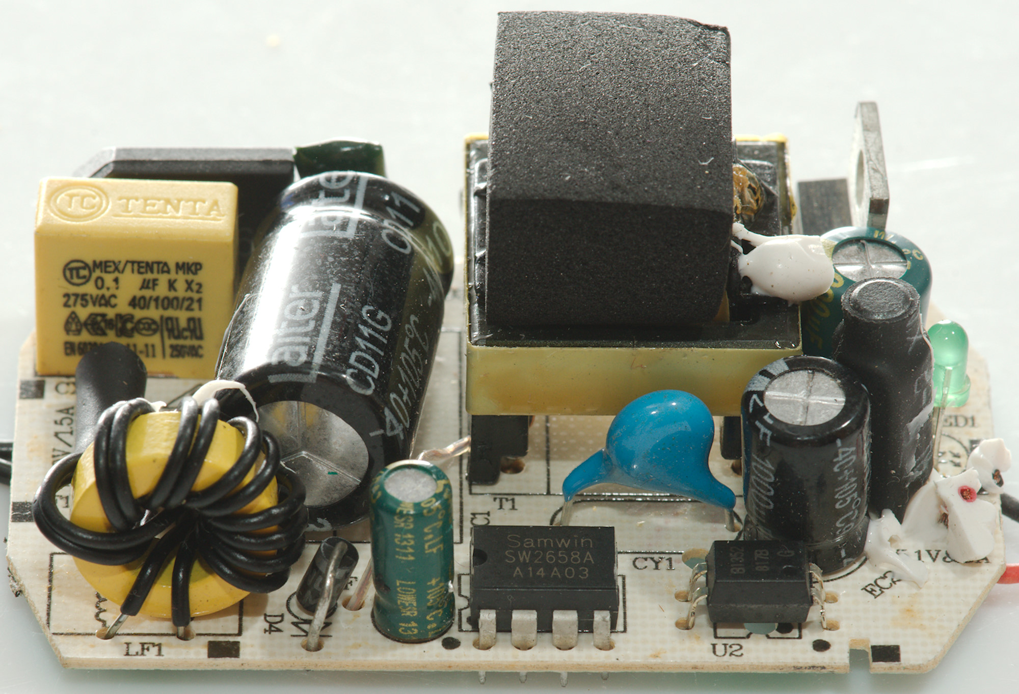
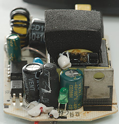
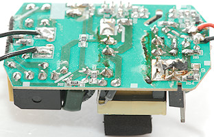
From this side the common mode coil can be seen, it do not look very nicely would. The switcher and optocoupler is also here.
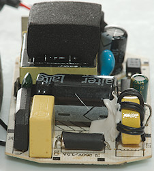
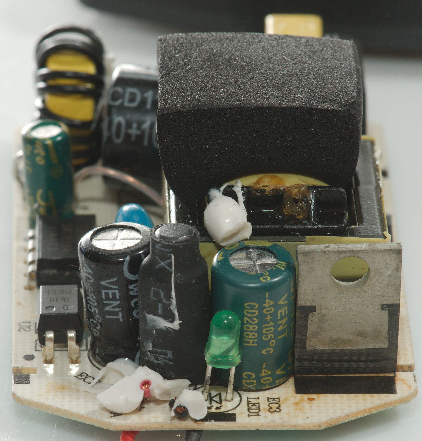
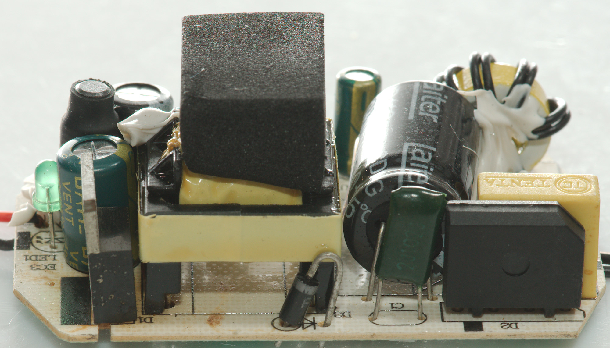
On first image is the led with the inductor behind it and the rectifier diode. The second image shows the fuse.
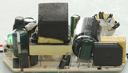
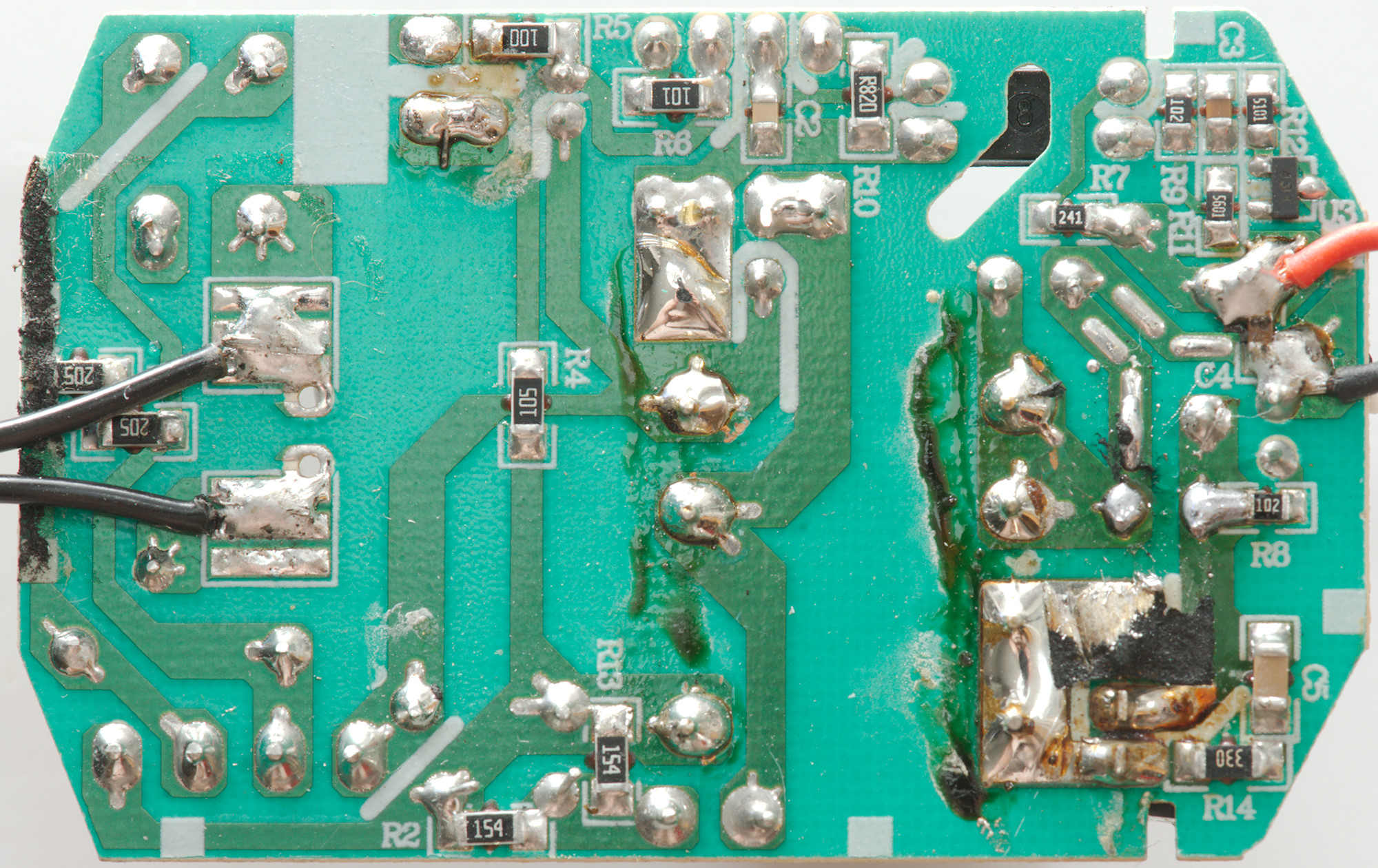
Here the rectifier diode (D1) can be seen again and the bridge rectifier (D2).
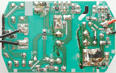
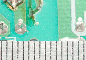
On the bottom is a few resistors and the reference (U3:431). Generally the circuit board do not look nice, especially around the pins from the rectifier diode (See bottom thermo photo).
Safety distance looks accetable.
Testing with 2830 volt and 4242 volt between mains and low volt side, did not show any safety problems.
Conclusion
This power supply have some noise and gets way to hot when delivering rated current (The diode needs a heatsink).
I doubt it will work for long time at full load, but it will probably work fine at low load.
Notes
Index of all tested USB power supplies/chargers
Read more about how I test USB power supplies/charger
How does a usb charger work?