AOKoda 7-27V to QC3.0
Official specifications:
- Brand: AOKoda
- Name: Lipo to USB Power Converter
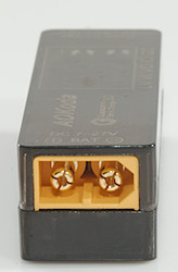
- Input: 7-27V(XT60/2-6s)Lipo Battery
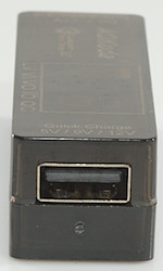
- Output: USB QC3.0/USB QC2.0/USB 5V(Max: 2.4A)
- USB QC3.0: 3.6V-6.5V/3A, 6.5V-9V/2A, 9V-12V/1.5A
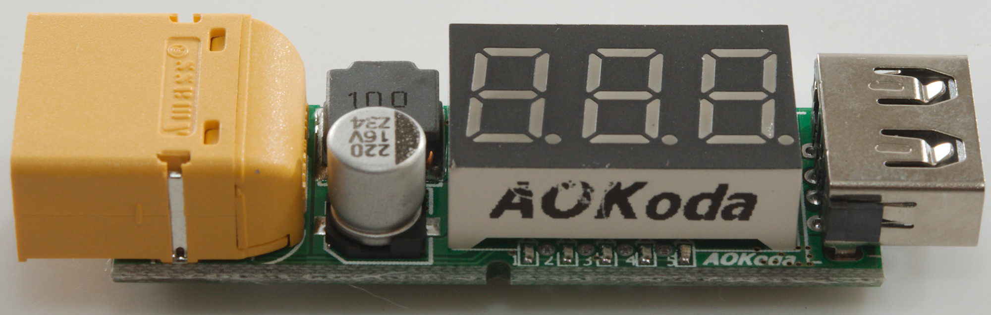
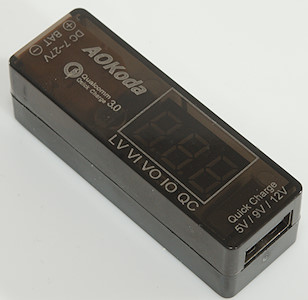
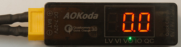
- LED meaning: LV(Low voltage number), VI(Input voltage), VO(Output power), IO(Output current), QC(Quick charge)
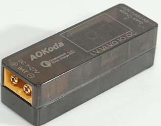
- Size: 63x 21x19mm
I got it from a Banggood.com
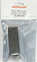
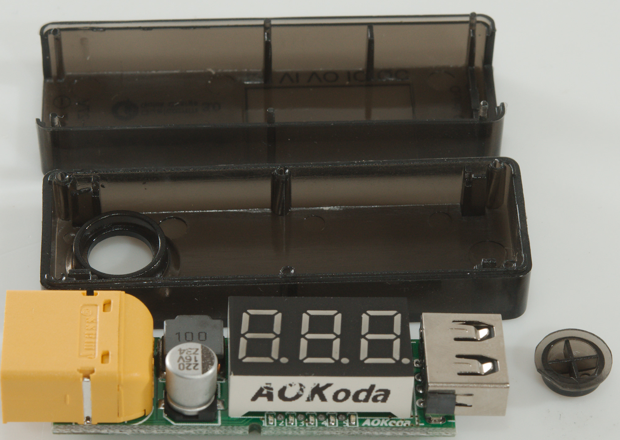
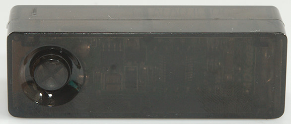
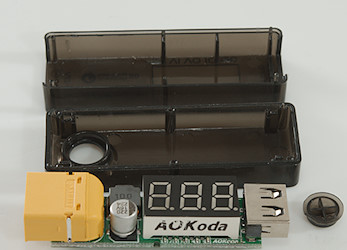
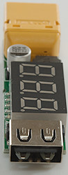
I got this charger in a plastic bag
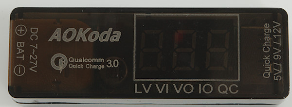
The letters: LV, VI, VO, IO, QC is markings for the 5 leds on the circuit board, but they do not align (sequence is correct).
They mean: Low voltage, Voltage input, Voltage output, Current output QuickCharge
During normal use the display will change between (LV when using LiIon), VI, VO, IO, when the button is held down it is possible to adjust LV if input is DC, with "BAT" input the low voltage is selected automatically to match a LiIon pack.
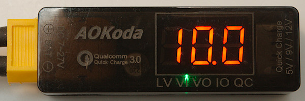
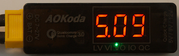
Vin, Vout and Iout
Measurements
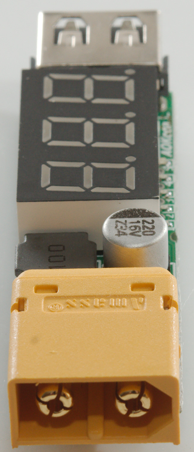
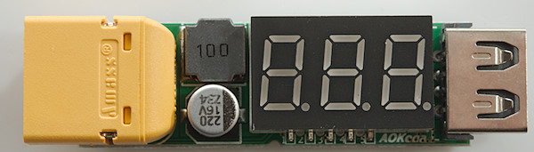
- Power input connector is XT60
- Power consumption when idle is 31mA at 27V and 21mA at 7V
- USB output is auto coding with DCP, Apple 2.4A, QC3, Huawei I-FCP, Samsung-AFC
- Minimum QC3 voltage is 3.5V
- Minimum manual protection voltage: 6.6V
- Maximum manual protection voltage: 24.0V
- LiIon voltage protection: 2: 7.4V, 3: 11.1V, 4: 14.8V, 5: 18.6V, 6: 22.2V
- Weight: 21g
- Size: 63mm x 21mm x 19mm
For all my test I uses a low voltage limit of 6.8V, except where otherwise noted.
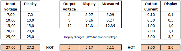
A check of display precision, it will say it is fairly good. The red line was done right after the 1 hour 5V 3A test where the device was very hot.
5 volt output
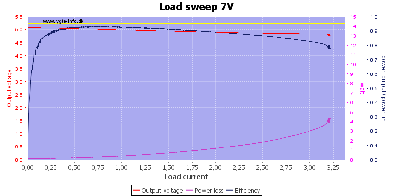
The minimum input voltage can only be used for 5V output and here it can deliver slightly above 3A before it starts switching off/on.
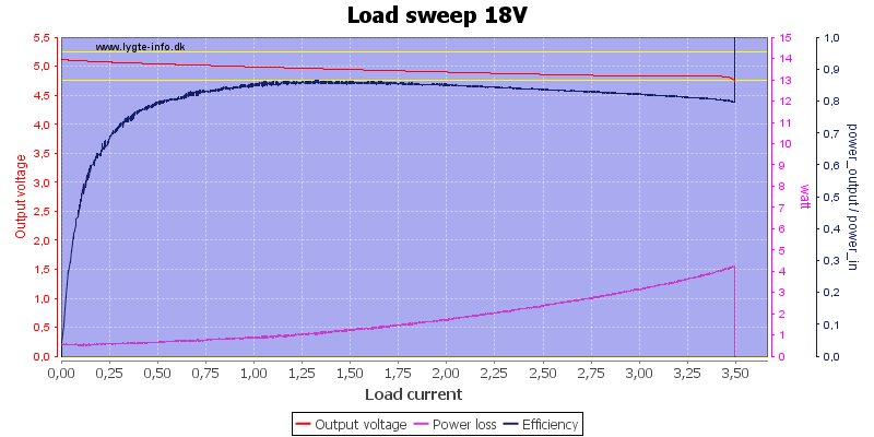
Higher input voltage increased the maximum output to 3.5A and reduces the efficiency a bit.
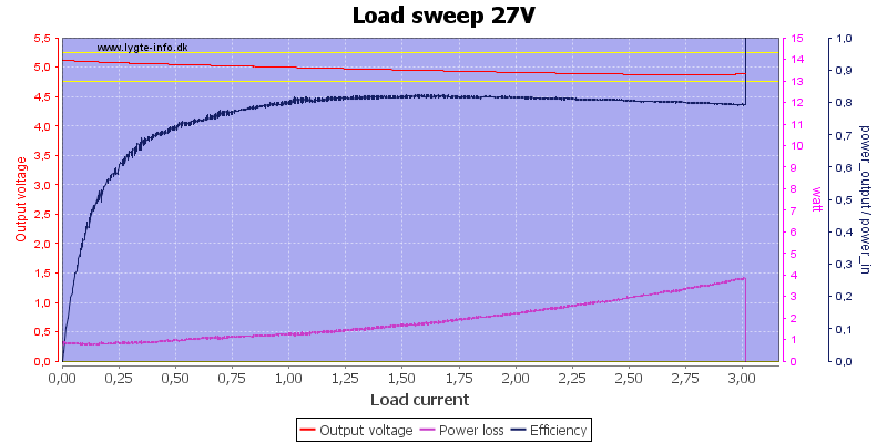
At 27V the drop in efficiency is very obvious, it is probably due to the linear regulator supplying the display.
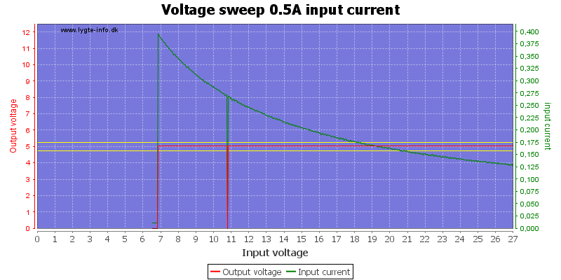
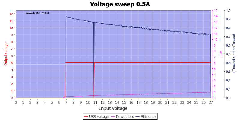
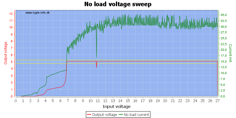
The output turns off at about 6.8V as selected, but there is a fallout at 10.8V.
I did check this fallout a bit more later on, but it did not show up when I just regulated the voltage around 10.8V
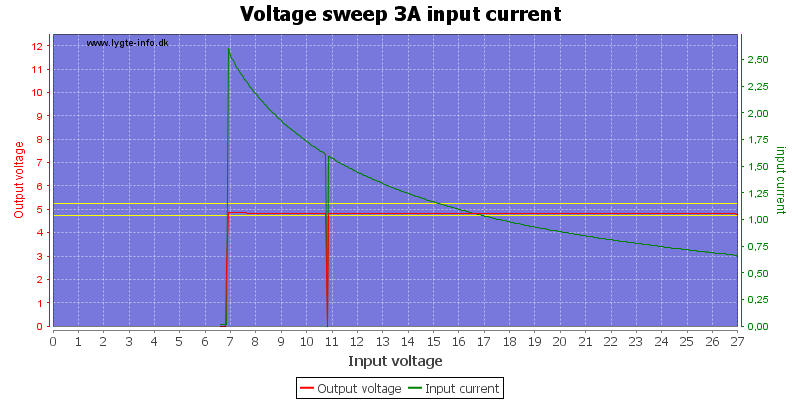
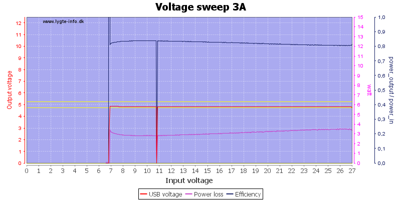
It is the same at 3A
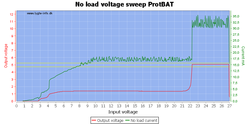
Using the BAT protection scheme means the device assumes 6s LiIon battery pack when I start with 27V and it will turn off at 22.2V.
The battery draw do not drop to 0, only to about 17mA, this means it is a good idea to disconnect the battery.
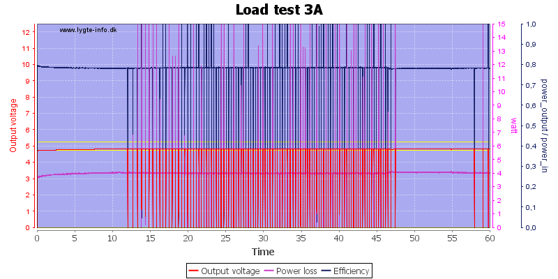
This test is at 5V and 3A, i.e. maximal QC2 output. This is the current where the effect loss in the device is close to maximum and just at the edge of device shutting down. When the device got hot it started to shut down for short periods. At 47 minutes I turned it around to take a IR photo and that gave some fresh air to the chip and cooled it down a bit.
The 12V section also contains a load test.
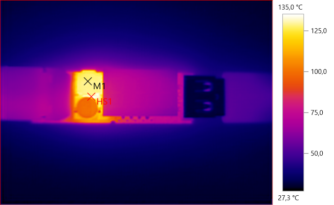
M1: 128.7°C, HS1: 135.0°C
The inductor is fairly hot.
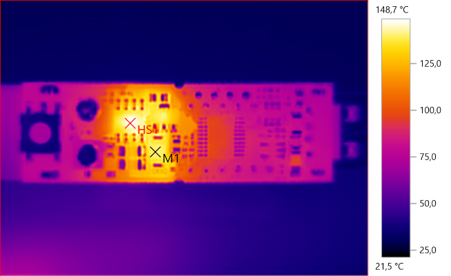
M1: 140.3°C, HS1: 148.7°C
The buck converter is very hot and the rectifier diode is close behind at this current level.
It is interesting to see the 0ohm resistor is slightly hot, there must be some resistance in it.
9 volt output
QC can deliver 9V output with 12V input.
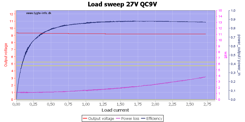
With 27V input the efficiency goes down at lower loads.
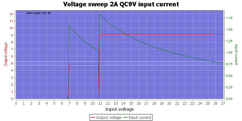
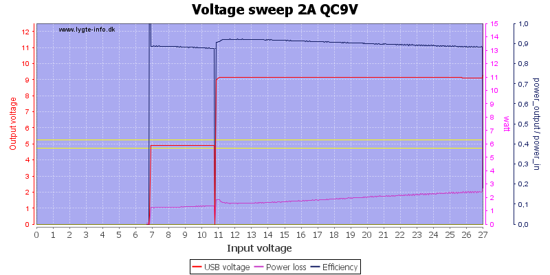
9V can be maintained down to about 11V with a 2A load, it is the same voltage as the fallout is at on 5V.
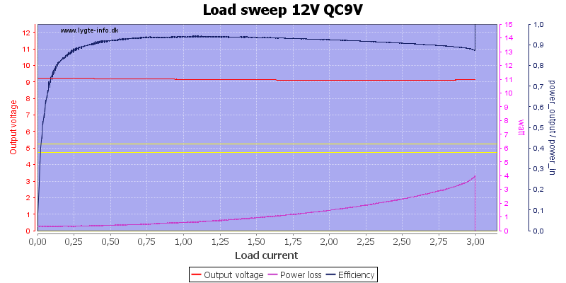
12 volt output
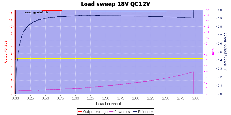
At 18V input the 12V Quick Charge can deliver nearly 3A (It is only rated for 1.5A)
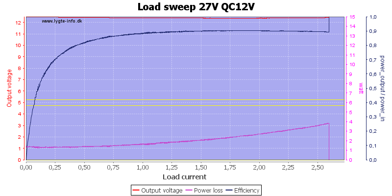
It is about the same with 27V input voltage.
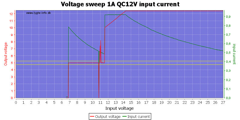
The charger can maintain 12V output down to about 14V input with 1A load. The spikes going up at 11V is probably the QC trigger trying to reengage QC 12V.
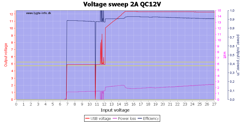
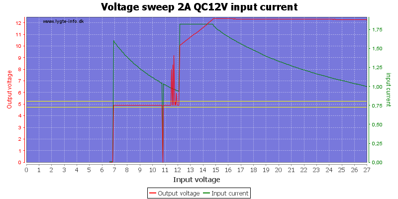
Using a 2A load the input voltage must be closer to 15V
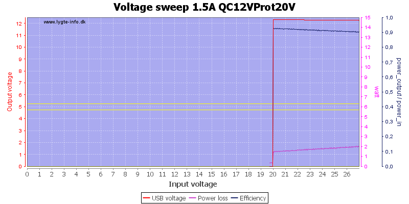
Here I raised the input protection to 20V and the output is turned off at 20V.
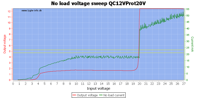
But the device is using a little bit of current after it turns off. It is around 20mA.
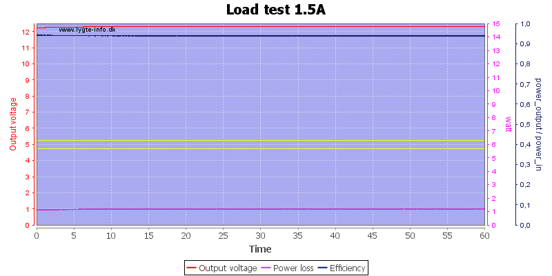
There was no problem running 1 hour with full 12V QC output. I used 15V for input.
The temperature photos below are taken between 30 minutes and 60 minutes into the one hour test.
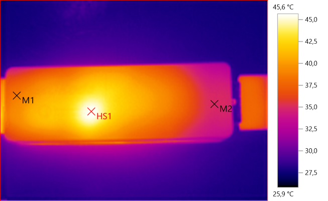
M1: 38.6°C, M2: 35.0°C, HS1: 45.6°C
The hot spot here is probably the inductor.
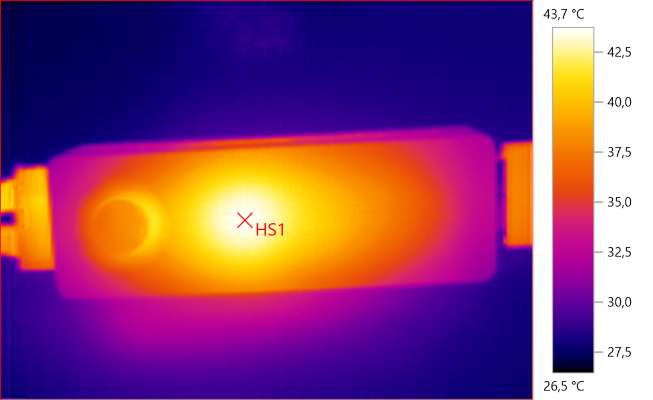
HS1: 43.7°C
On this side it may be a combination of inductor, buck converter and rectifier diode.
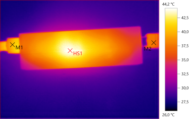
M1: 40.1°C, M2: 37.6°C, HS1: 44.2°C
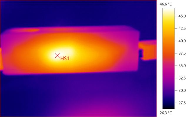
HS1: 46.6°C
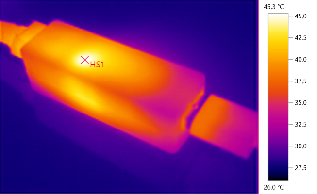
HS1: 45.3°C
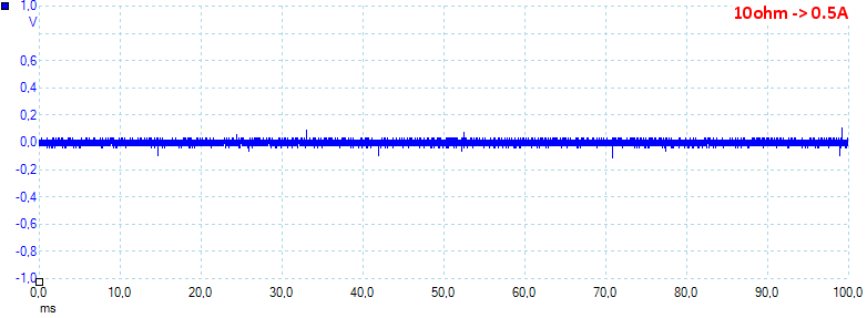
The noise at 0.5A is 23mV rms and 220mVpp, all noise charts are made with 27V input, because that gave the most noise.
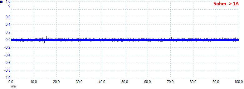
The noise at 1A is 22mV rms and 189mVpp
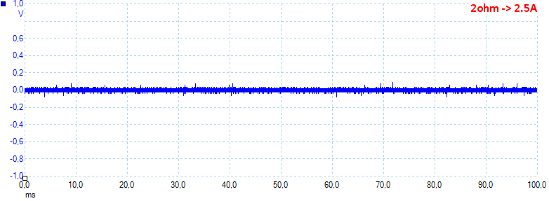
The noise at 2.5A is 22mV rms and 168mVpp.
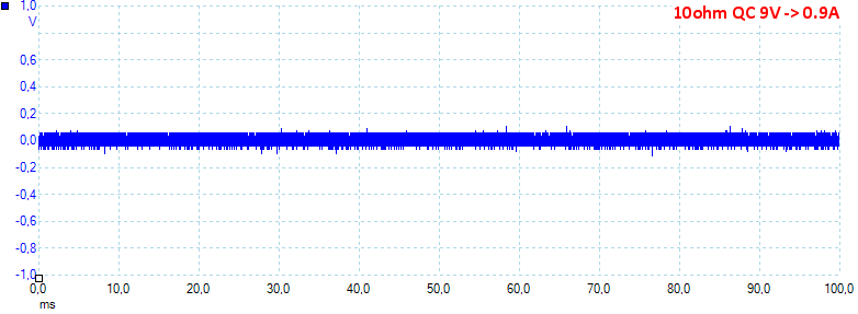
The noise at 9V and 0.9A is 39mV rms and 280mVpp.
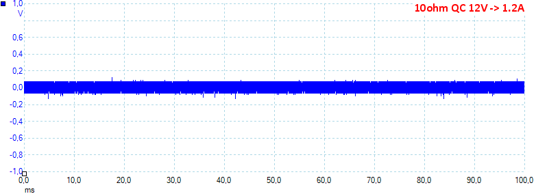
The noise at 12V and 1.2A is 50mV rms and 280mVpp.
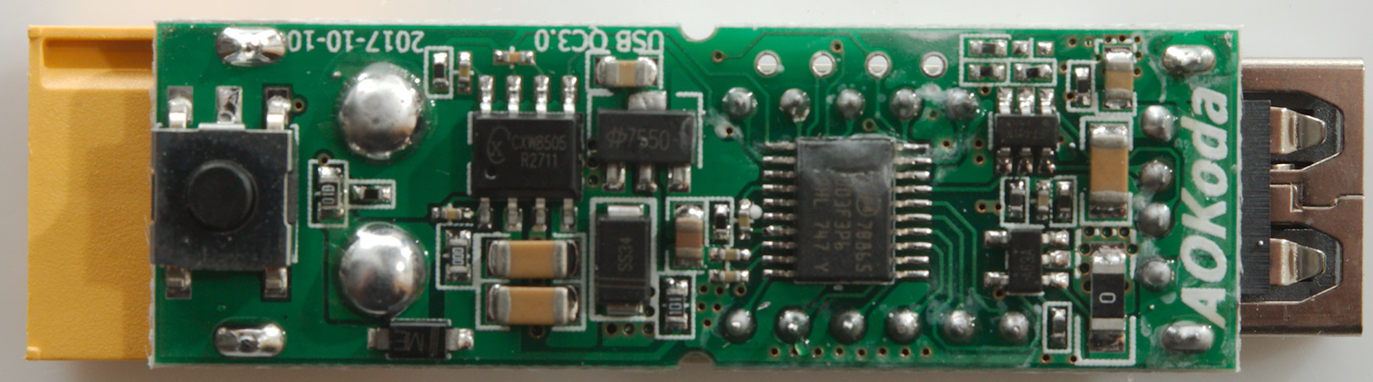
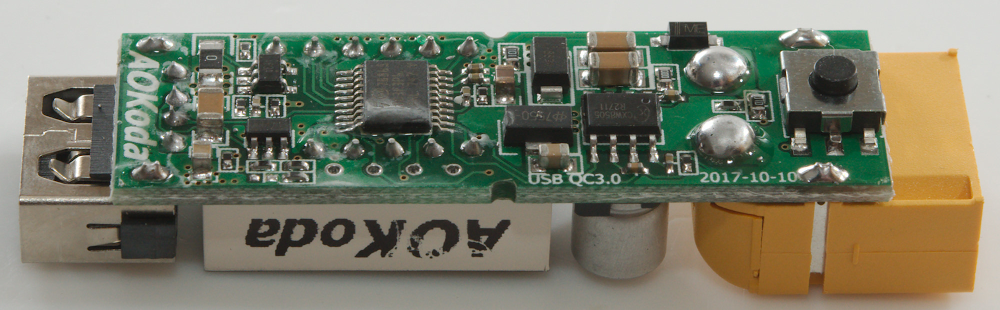
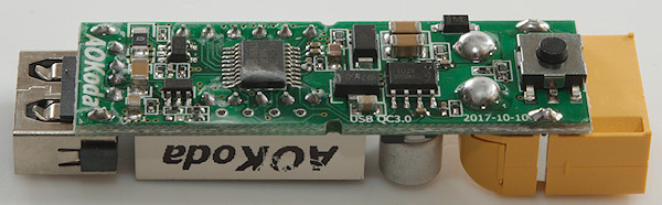
Tear down
There is no screws or clips, I could just pull it apart.
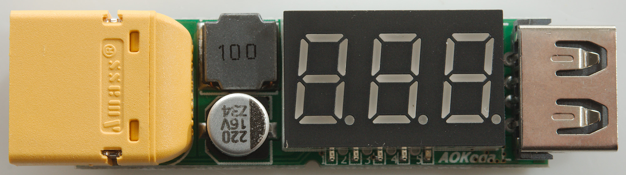
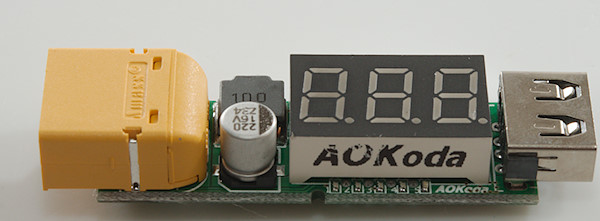
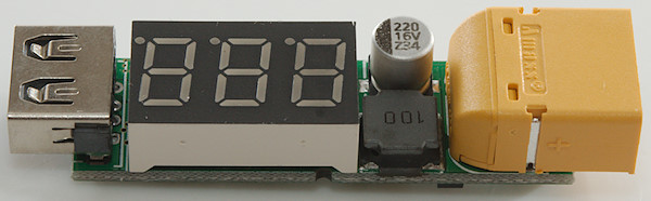
On this side is the display, a couple of leds (5), a inductor and a output capacitor.
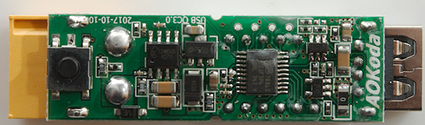
At the input is a buck regulator (CXW8505) used for output voltage and it uses a SS34 as rectifier diode. The processor and display need a stable voltage and uses a linear regulator (7550: 5V 100mA with a max. input of 24V). The processor (STM8S003F3P6 8kB flash, 1kB ram, 5*10bit ADC) handles the display and the voltage limit. The actual QC is done my a 6 pin chip (FT4) and there is a OpAmp (A63A: LM321) next to it, it is probably measuring the current across some resistance, but I do not see a resistor for it (Maybe they use the 0ohm resistor).
Being a low volt device there is no need to test with high voltages.
Conclusion
A useful device for people that uses LiIon battery packs, it is easy to carry around and it can make them into QC3 power banks. I can, of course, also be used from other power sources.
The 3A rating for 5V QC is a bit optimistic, but then very few devices uses 3A and I do not believe it is much of a problem. It supports a lot of fast charging protocols, this means most phones will charge fairly fast on it.
Notes
The usb charger was supplied by a Banggood.com for a review.
Index of all tested USB power supplies/chargers
Read more about how I test USB power supplies/charger