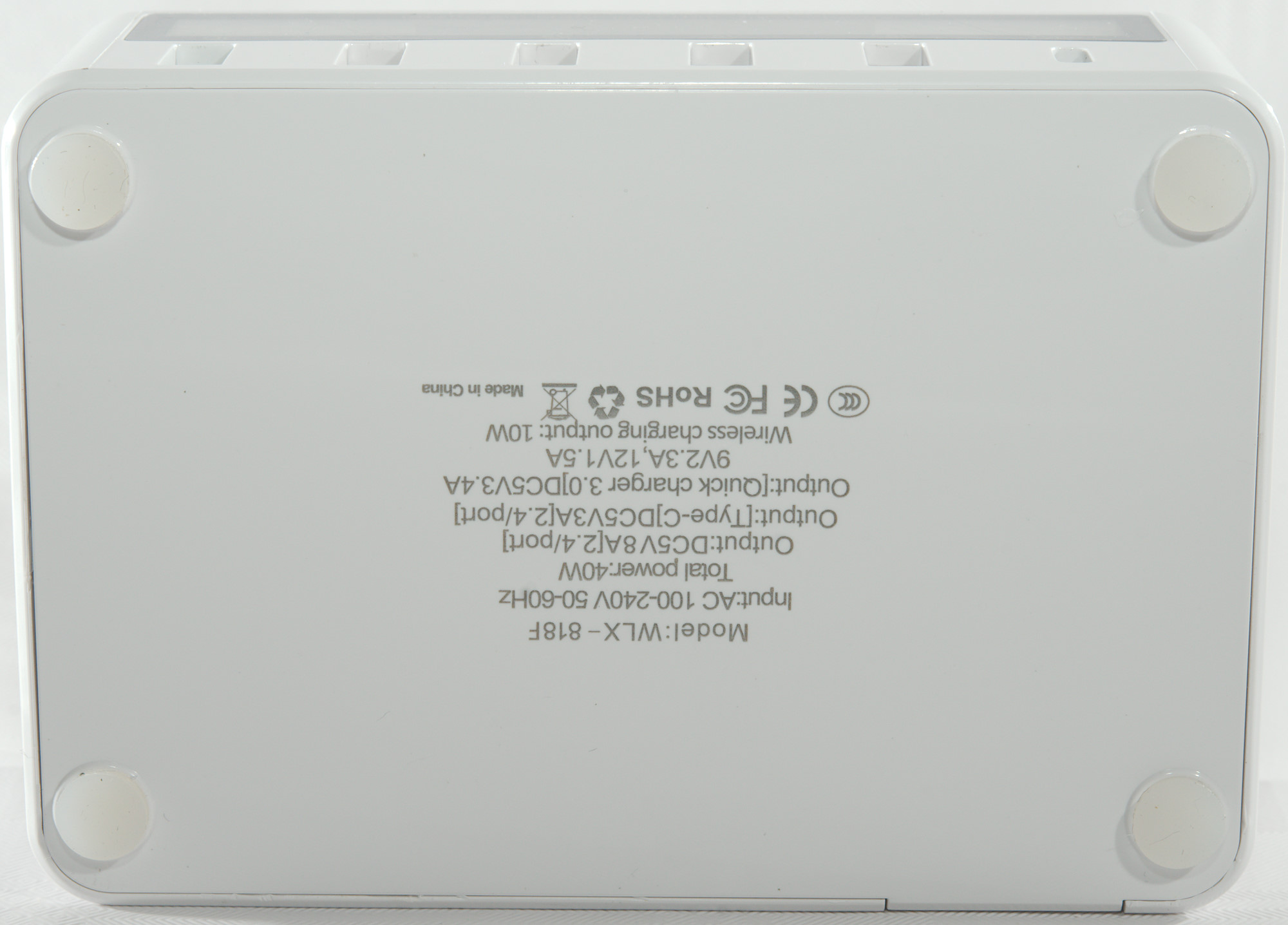
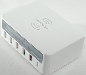
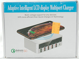
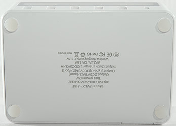
Adaptive Intelligent LCD display Multiport Charger WLX-818F
Official specifications:
- Output QC3: 5V 3.4A, 9V 2.3A, 12V 1.5A
- Output USB-C: 5V 3A
- Output: USB: 2.4A/port 8A total
- Total power: 40W
- Input Type: AC 100-240V
I got it from gearbest
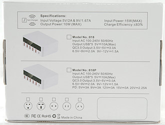
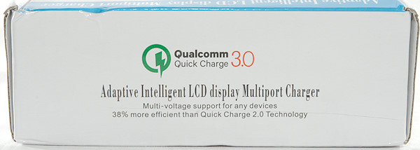
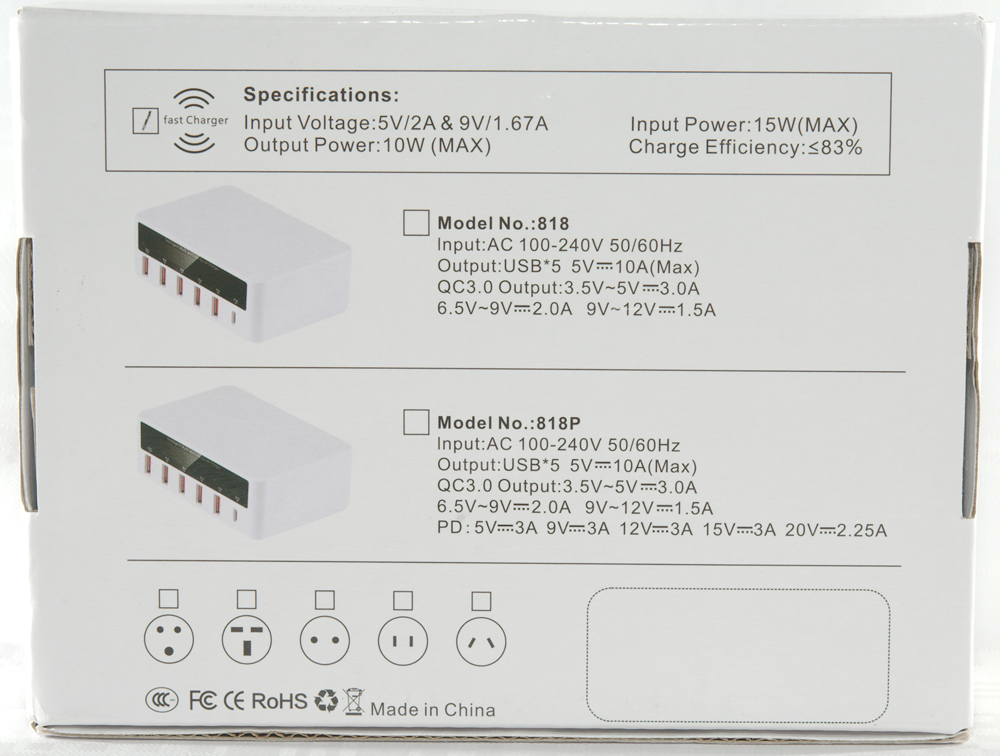
The box has specifications for two models of the charger, but neither matches the charger in the box.
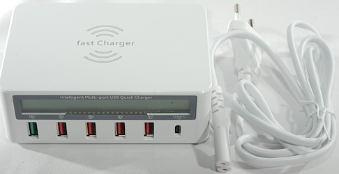
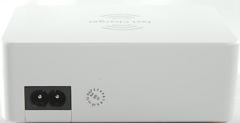
Inside the box was the charger and a mains cable.
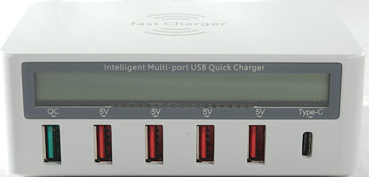
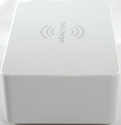
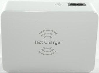
The charger has lot of outputs: QC, 4xUSB, USB-C (It is not a full PD) and a QI on top.
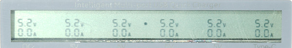
The display show voltage and current for each output, except QI. There will be animated markers around the center dot when QI draws power.
Measurements
- Power consumption when idle is 0.3 Watt
- USB-C output is always on.
- QC output is coded as Apple 2.4A, DCP, QC3, Samsung-AFC, Huawei-FCP
- Minimum QC3 voltage is 5V.
- Standard USB outputs are coded as Apple 2.4A and DCP
- Voltage display always shows 5.2V (except QC) and not the actual output voltage.
- QC voltage can show 5.2V, 9.2V and 12V, depending on voltage.
- All outputs are in parallel, QC has a boost converter from 5V.
- At 3.7A USB current QC cannot deliver 12V 1.5A anymore (36 watt)
- At 5.2A USB current QC cannot deliver 12V 1A anymore (38 watt)
- Weight: 253g
- Size: 115.5x 80.0 x 42.0mm
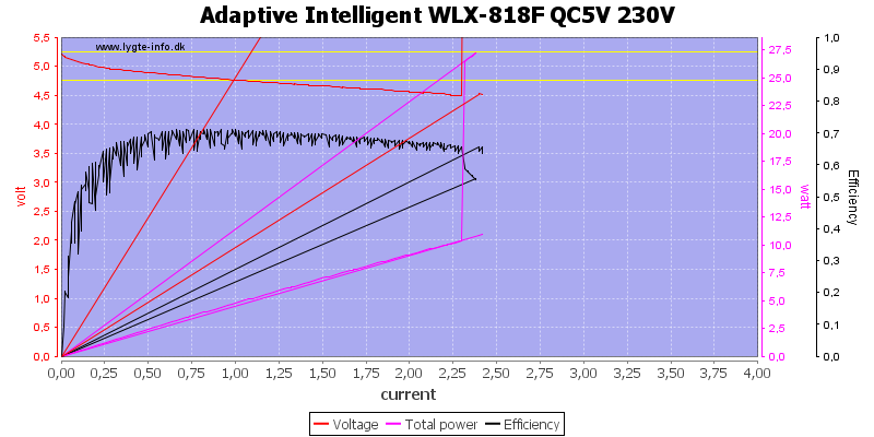
The QC rating is way to high, the charger can only deliver about 2.2A
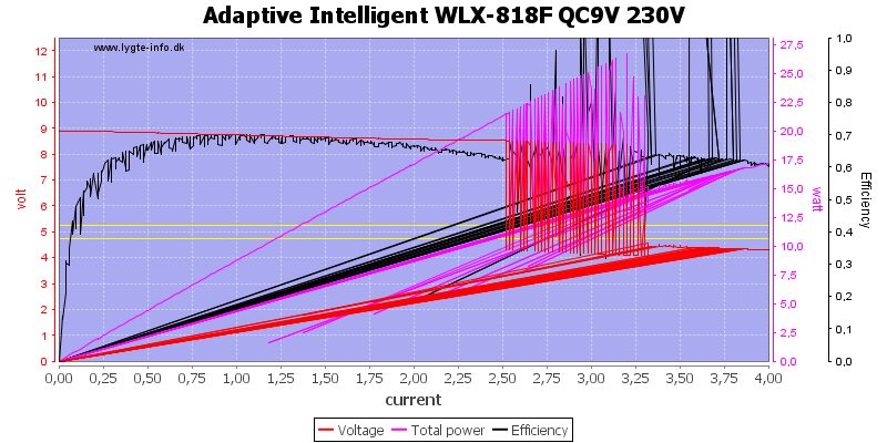
At 9V it can deliver 2.5A, this is more in line with the rating of 2.3A
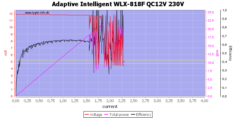
At 12V it can deliver about 1.5A
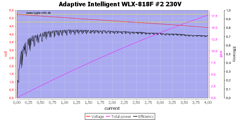
The regular USB outputs are not individually overload protected and can deliver lots of current, but the voltage will drop. This drop is probably due to the current sense resistor for the ammeter.
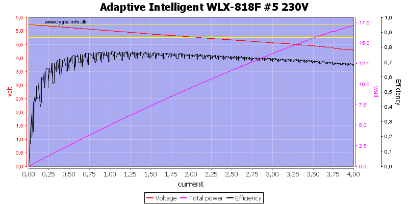
Another output looks similar.
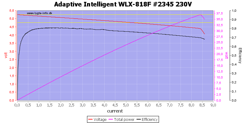
Running all in parallel and the overload protection shows up, it is at about 8.5A, this is WAY to much for a single USB connector.

At 120VAC input the current is slightly lower.
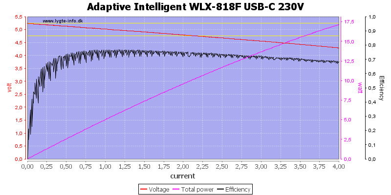
USB-C looks similar to normal USB outputs.
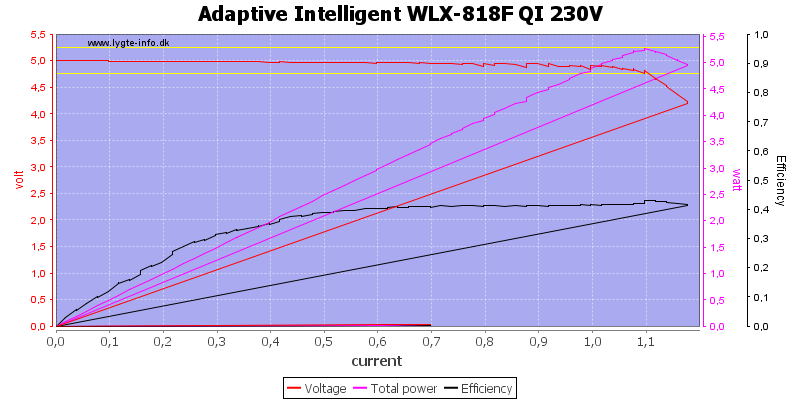
I could draw about 1A from QI, but I had problems getting it to work.
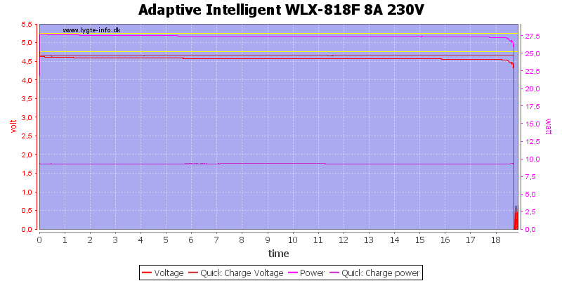
My first load test was with a 40W (8A) load distributed on QC and normal USB, it only worked for a bit above 18 minutes.
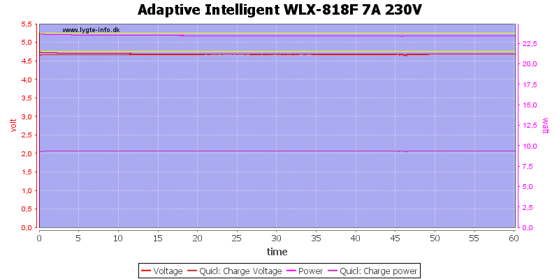
I reduced the total load a bit to 7A and it was possible to do a one hour test.
The temperature photos below are taken between 30 minutes and 60 minutes into the one hour test.
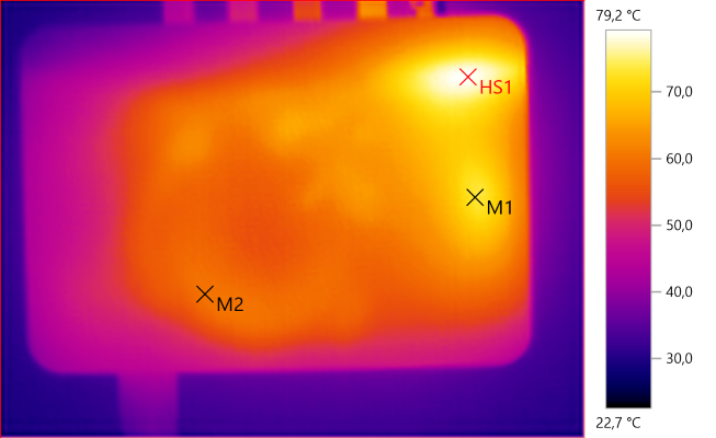
M1: 73.0°C, M2: 60.1°C, HS1: 79.2°C
HS1 is the QC inductor.
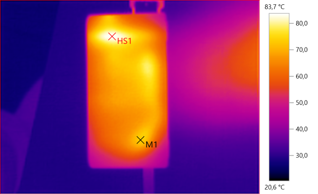
M1: 73.4°C, HS1: 83.7°C
HS1 is again the QC inductor.
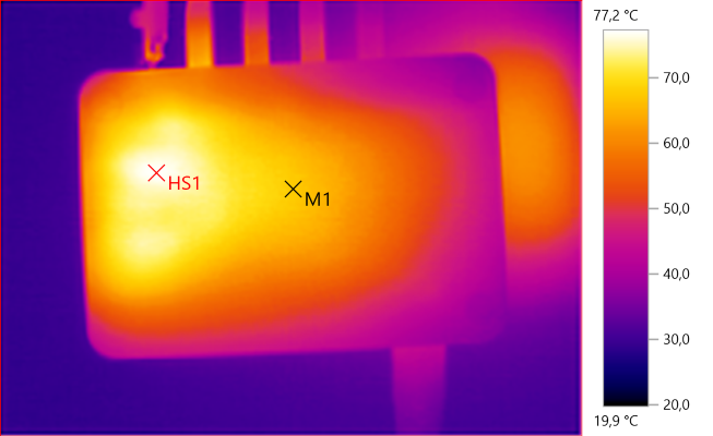
M1: 67.6°C, HS1: 77.2°C
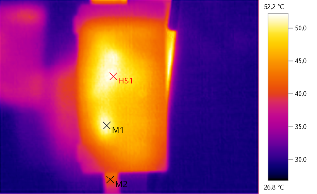
M1: 51.3°C, M2: 41.2°C, HS1: 52.2°C
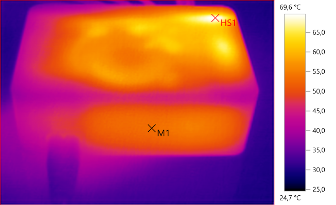
M1: 53.6°C, HS1: 69.6°C

M1: 68.2°C, M2: 71.5°C, HS1: 71.9°C
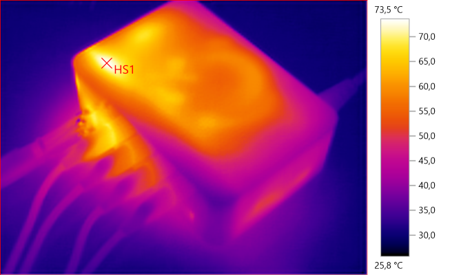
HS1: 73.5°C
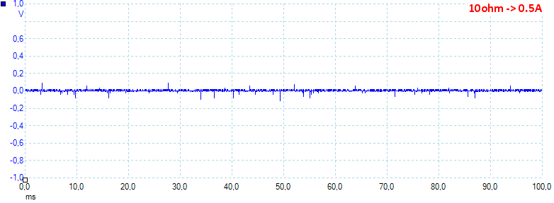
At 0.5A load the noise increases to 23mV rms and 600mVpp.
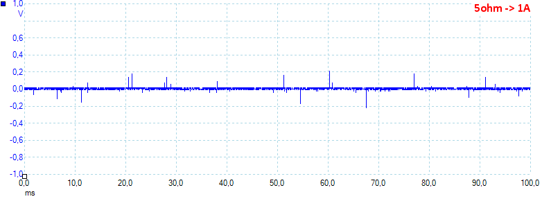
At 1A load the noise increases to 14mV rms and 582mVpp.
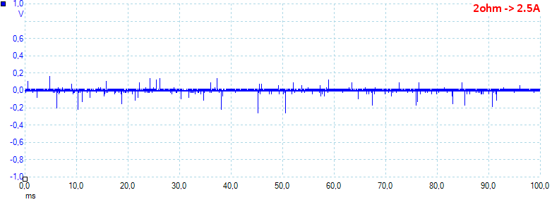
At 2.5A load the noise increases to 33mV rms and 670mVpp.
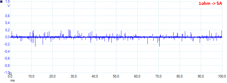
At 5A load the noise increases to 21mV rms and 679mVpp, there is some spikes for the peak noise, this is probably due to missing mains filtering.
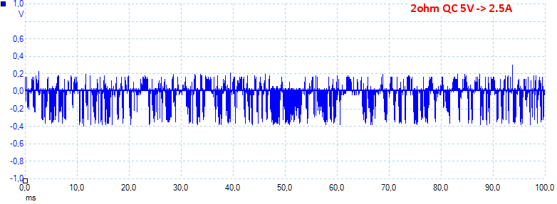
At QC 5V 2.5A load the noise increases to 146mV rms and 1010mVpp.
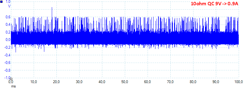
At 9V 0.9A load the noise increases to 158mV rms and 1205mVpp.
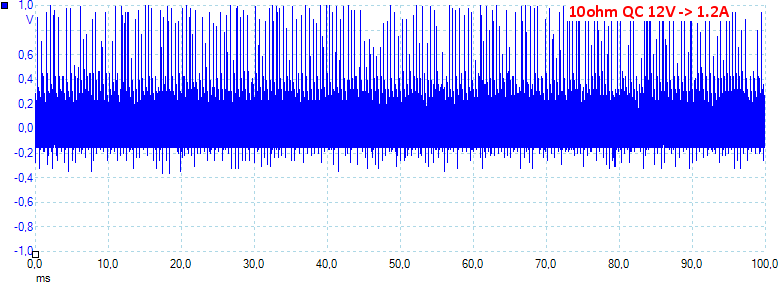
At 12V 1.2A load the noise increases to 270mV rms and 1789mVpp, the QC output has a lot more peak noise and at very high levels.
Tear down
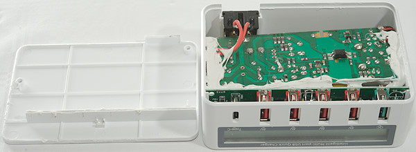
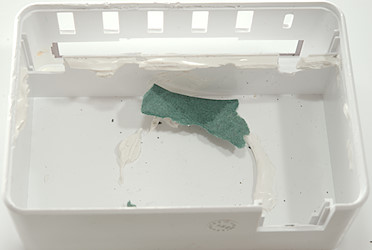
There was no screws, but I could break the bottom off.

There is at least two circuit boards and lots of glue.
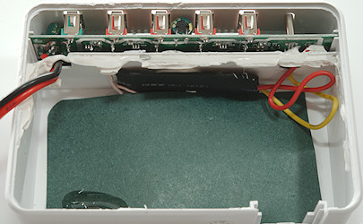
The power supply module has been removed, the QI antenna is behind the gray paper and the QI circuit board is behind the black.
Everything is out, but I broke the QI antenna while trying to break it loose from the glue.

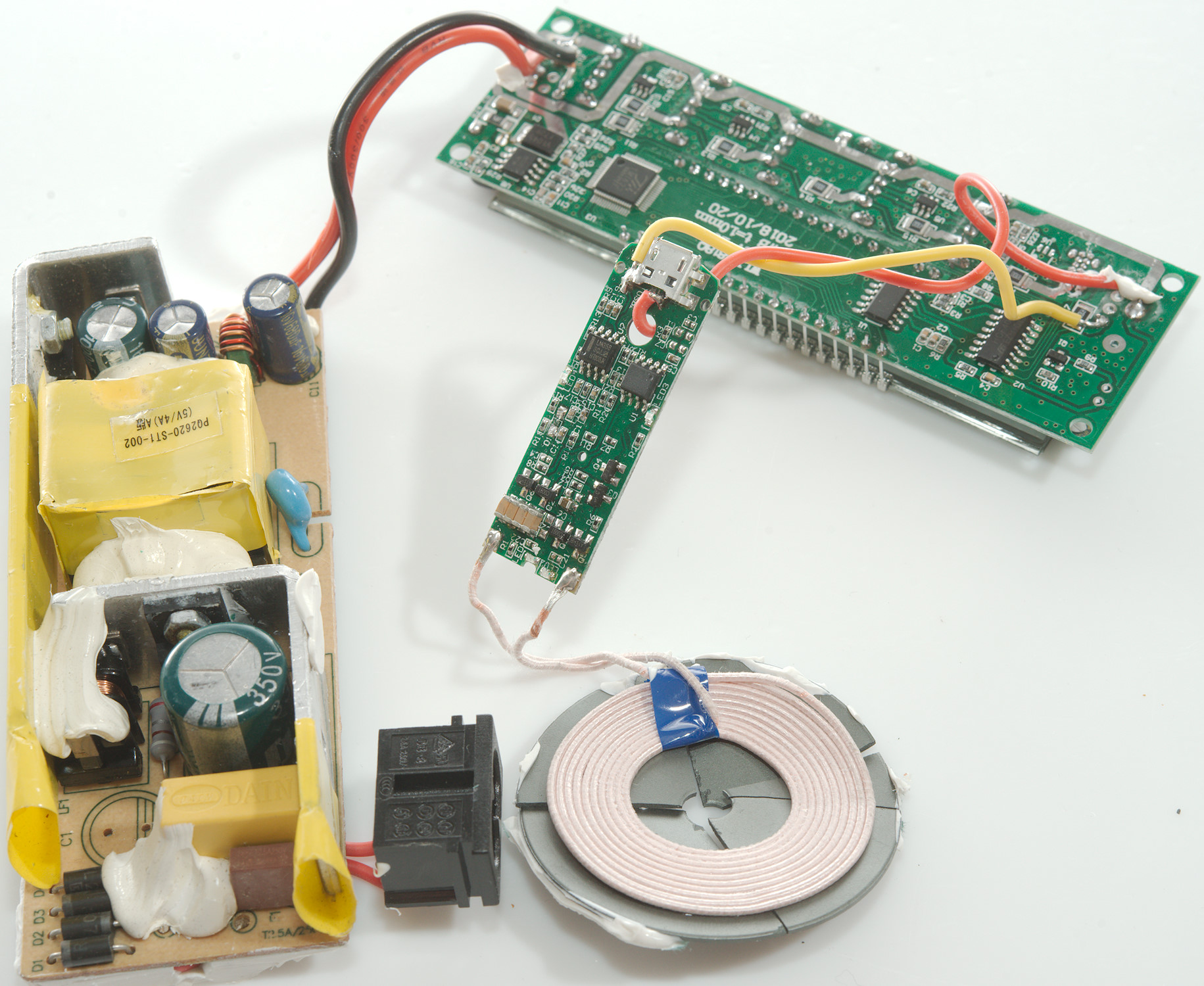
The contents of the charger: A power supply module, a USB output module, a QI module and a QI antenna.
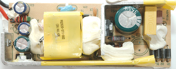
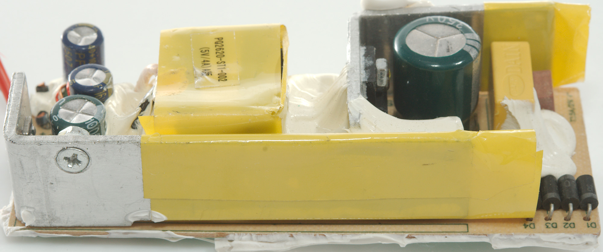
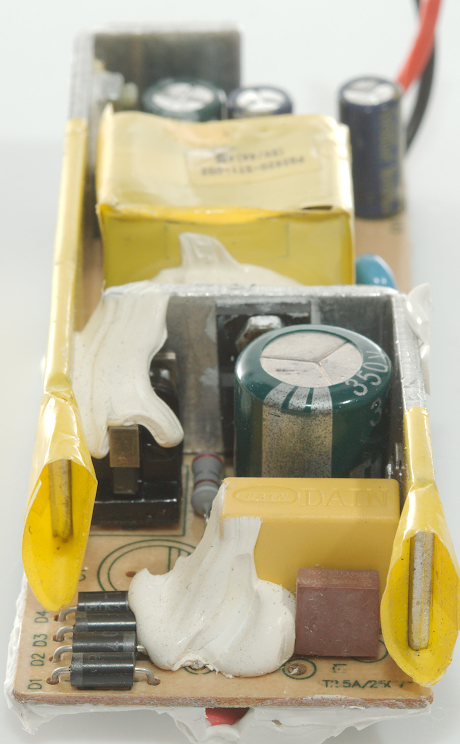
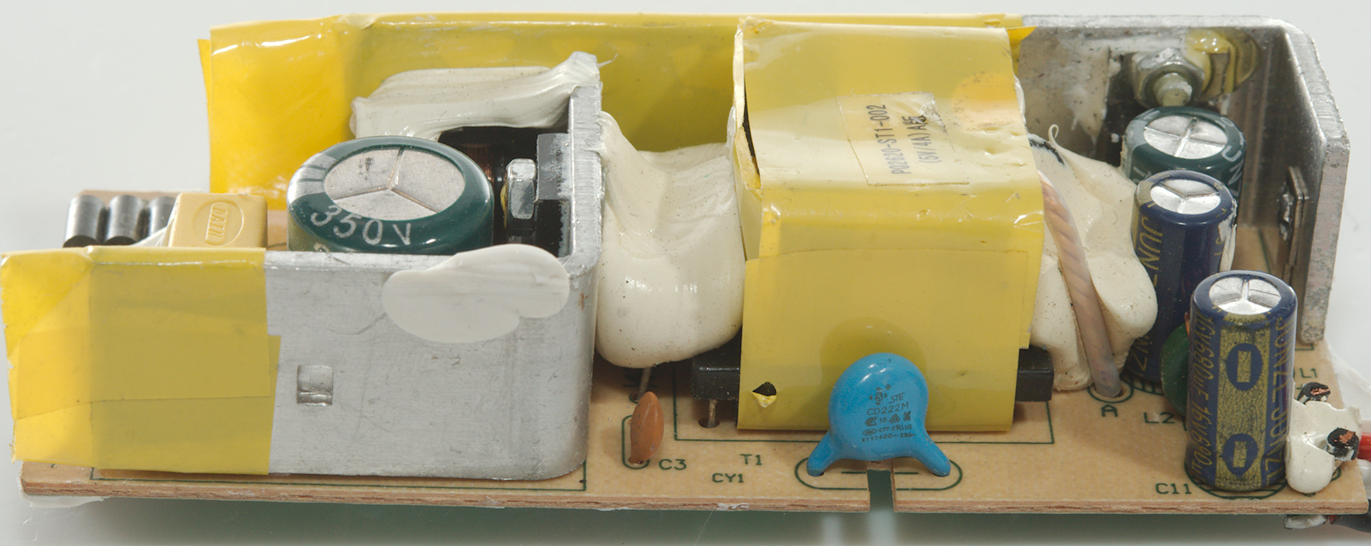
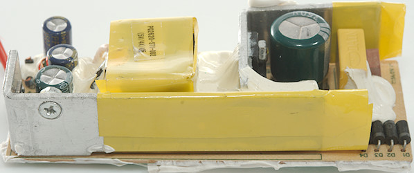
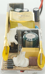
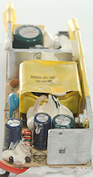
The power supply module looks fairly standard, but old fashioned. At the input is a fuse and four diodes for a bridge rectifier. There is also a common mode coil below the white stuff., the mains switcher is mounted on a heatsink.
There is a safety capacitor between mains and low volt side and on the low volt side the rectifier diode is mounted on the largest heatsink. At the output is a output inductor.

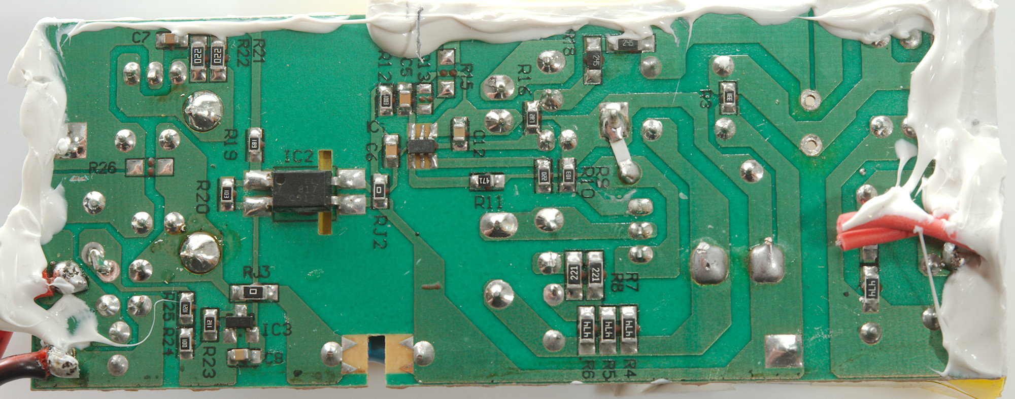
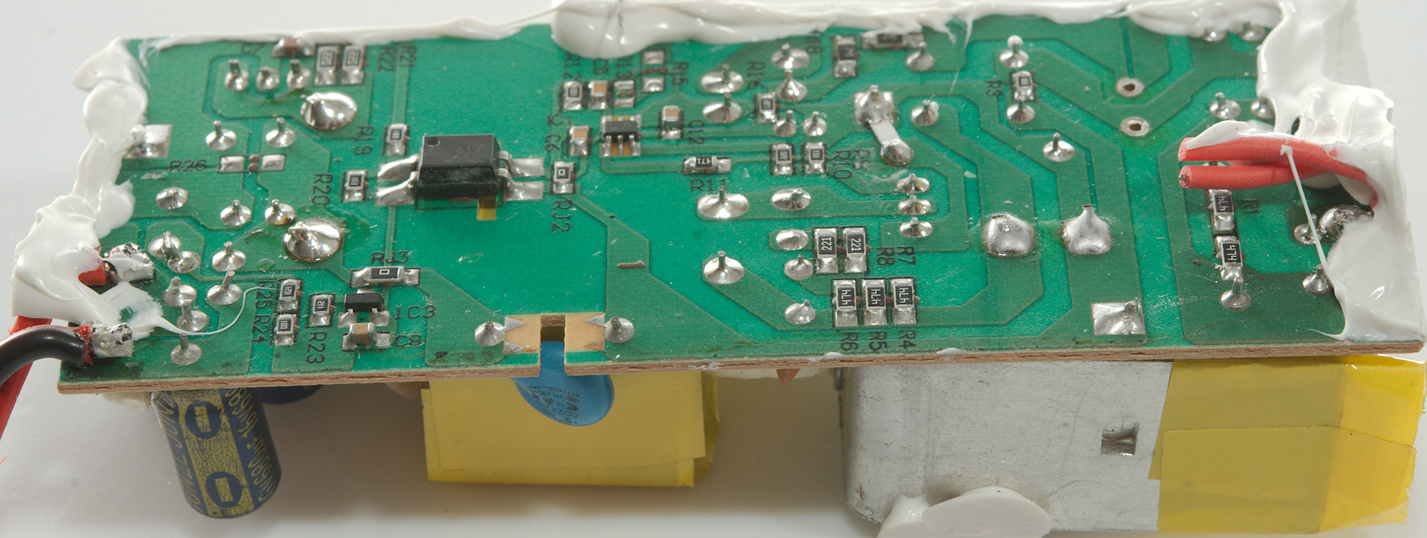
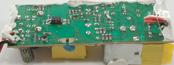
On this side is the mains switcher controller (A 6 pin IC marked 6000A / FS008). There is opto feedback from the low volt side with a reference (IC3: 431).
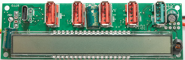
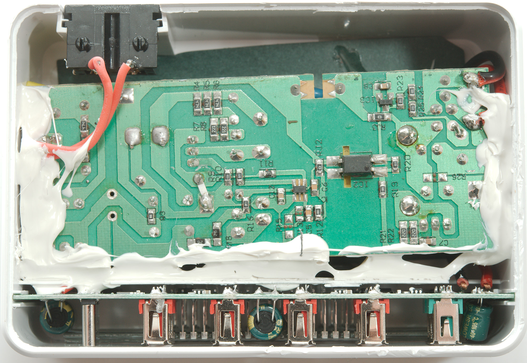
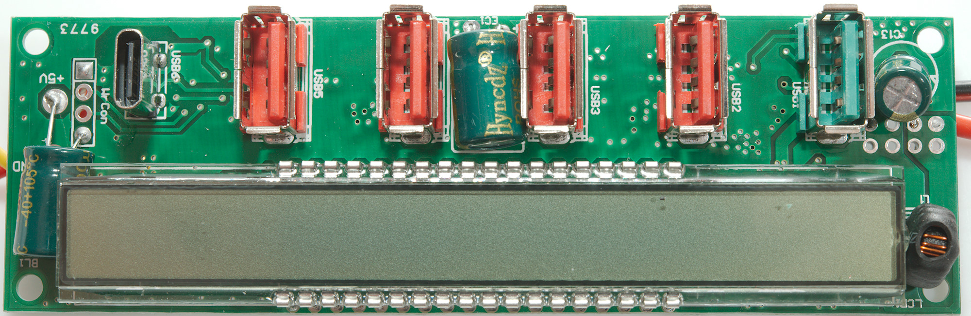
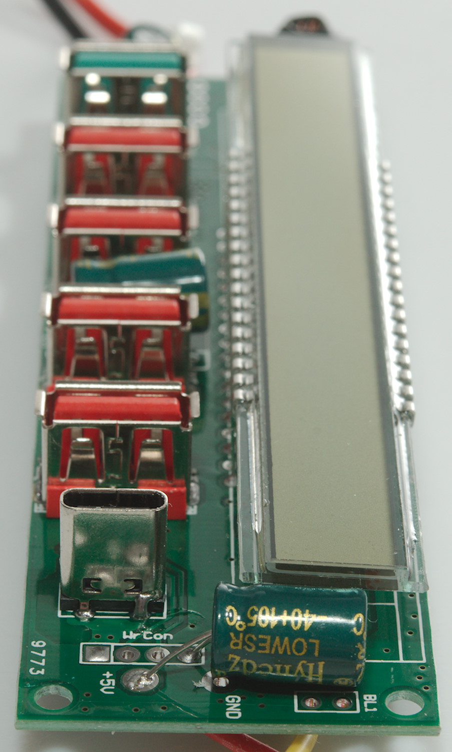
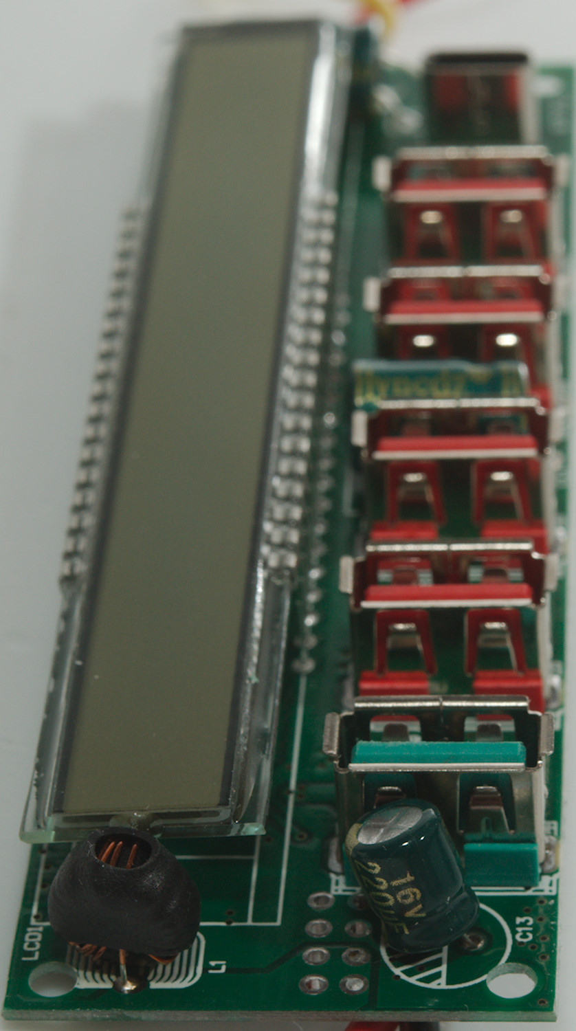
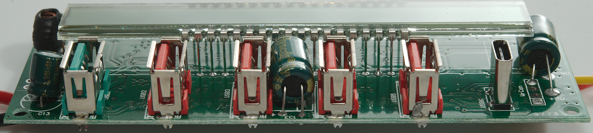
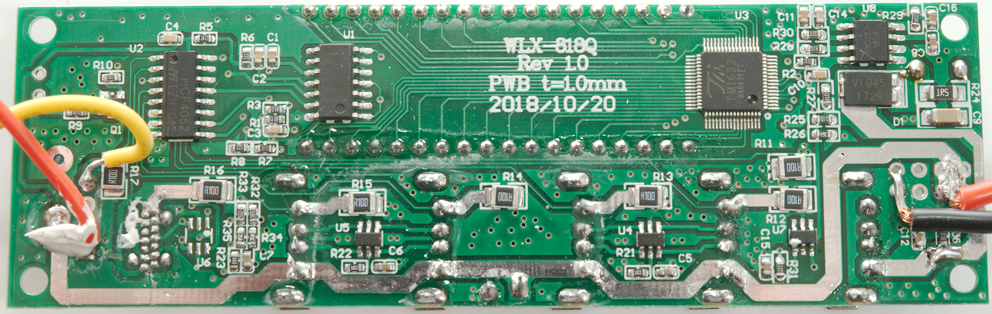
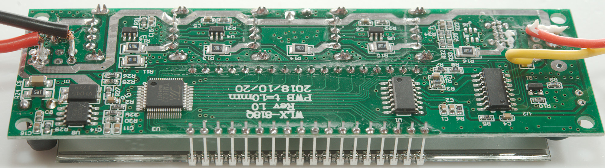
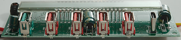
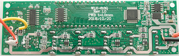
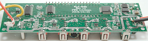
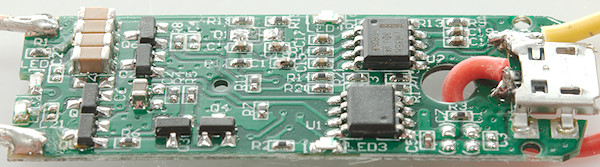
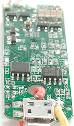
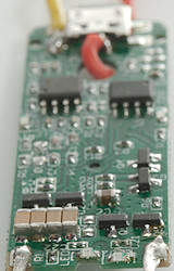
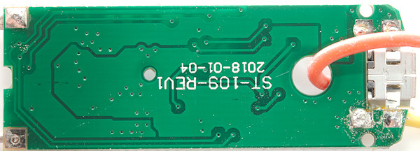
Next in line is the USB output circuit with 6 USB connectors and a long display. For QC the small inductor (L1) at the end of the display is used to boost the 5V.

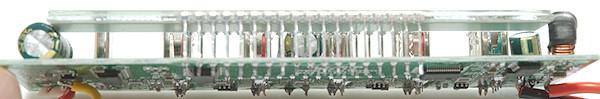
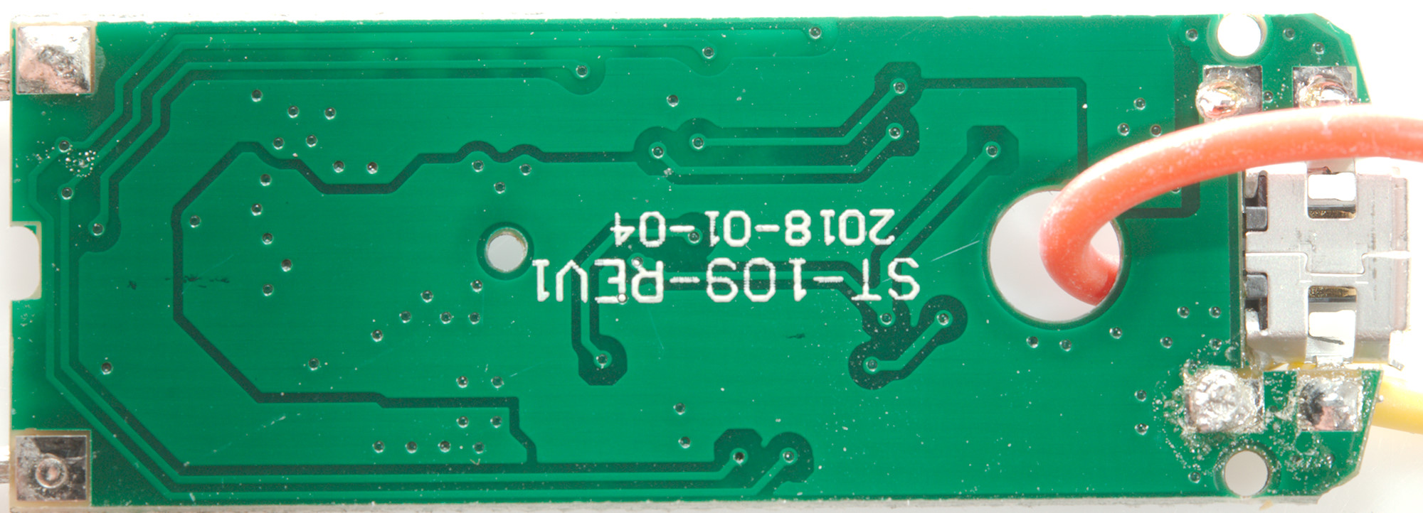
There is nothing below the display.
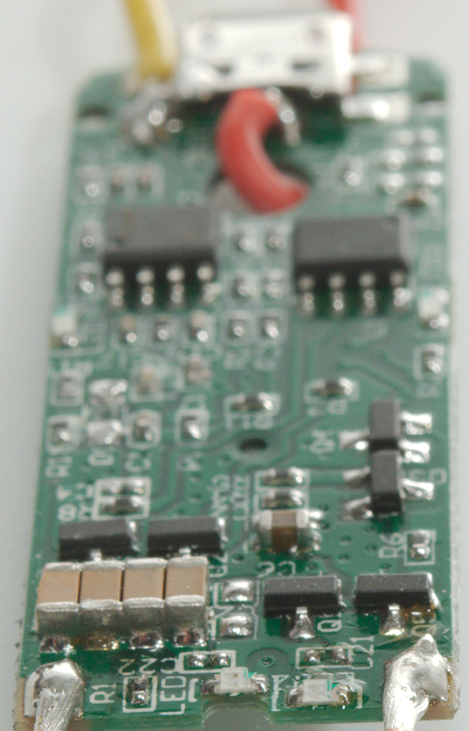
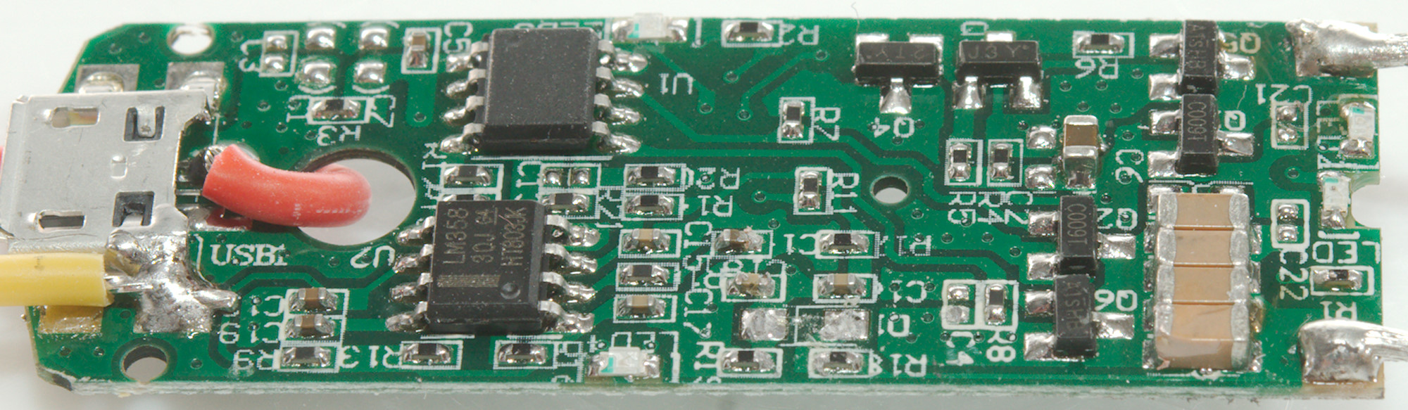
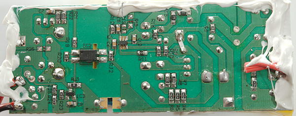
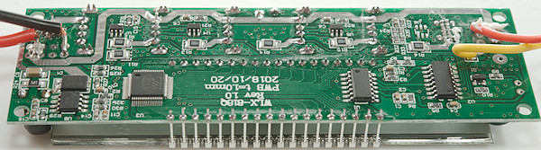
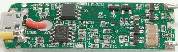
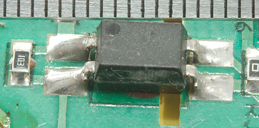
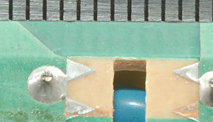
This side of the circuit board is more interesting. Near the power input is the QC boost regulator (U8: Marked YNS223 / 1808), next to a diode (D1: V10P45), next up is the LCD driver (U3: TM1622). Then is the microprocessor (U1: Unmarked) and a multiplexer (U2: HEF4052) to handle all the current inputs. For sensing current there is a resistor for each output (R11, R12, R13, R14, R15, R16, R17: 0.1ohm), this also includes QI. There are two auto coding chips (U4 & U5: Marked A12X), there is also space for one (U6) at the USB-C output, but it is not mounted.
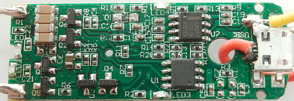
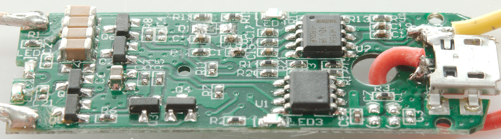
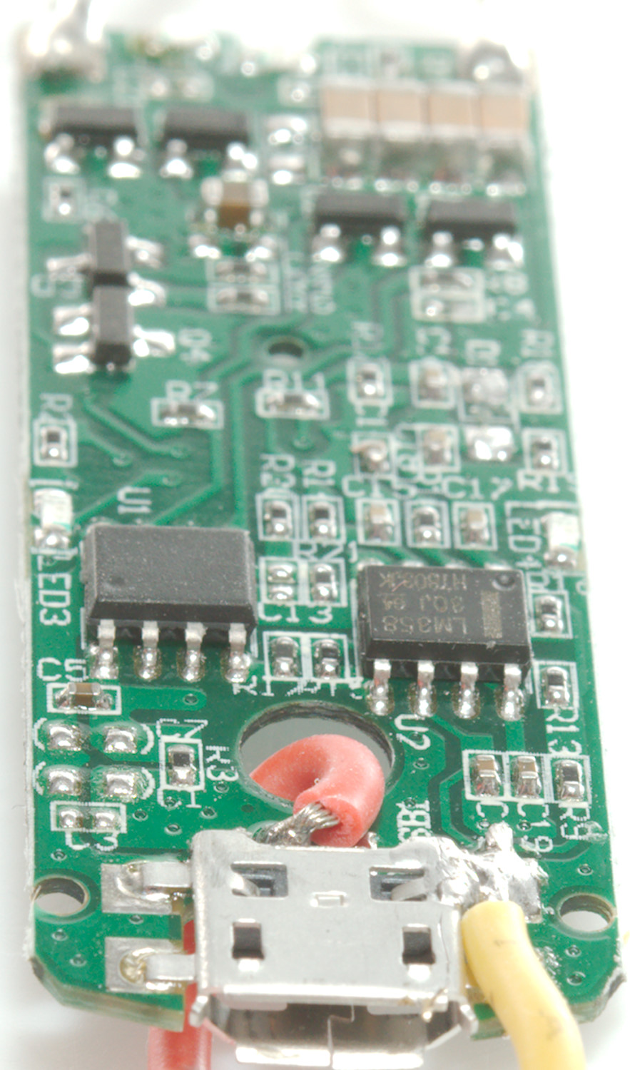
The QI module is a USB powered module, as can be seen on the mounted USB connector. On the module is a OpAmp, a unmarked QI chip and some driver transistors and capacitors for the coil.
The isolation distance between mains and low volt side is good.
Testing with 2830 volt and 4242 volt between mains and low volt side, did not show any safety problems.
Conclusion
This USB charger is thrown together from some standard parts (power supply and a QI module) and the USB output part is probably designed for it and this design has a couple of problems: The QC charger is not very good. All outputs will drop when loaded due to the sense resistor. The voltage display is fake, no actual measurements are done. USB-C is not real PD, but just a 5V USB voltage. A single USB output can deliver 8A, this is way to much.
The efficiency of the power supply is a bit low, this means the charger gets fairly warm when deliver lots of current.
Notes
Index of all tested USB power supplies/chargers
Read more about how I test USB power supplies/charger