Allmaybe 6 port 60W CU6
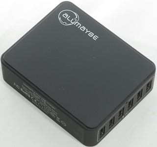
Official specifications:
- Power: 60W
- Input: 100-240V~1.45A 50-60Hz
- DC Output: 5V/12A(each port 2.4A max)
- Size: 99(L) x 80(W) x 29(H) mm / 3.9(L) x 3.1(W) x 1.1(H) in
- Weight: 198g/7.0 oz
I got it directly from Allmaybe
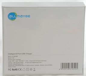
I got it in a simple white cardboard box.
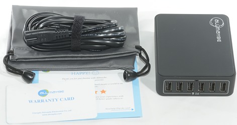
The box contained the charger, a mains cable, a pouch, a warranty note and a note. There was no manual and it is not really needed for this usb charger.
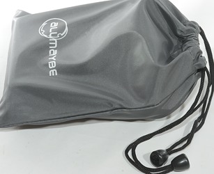
Charge and mains cable in the pouch.
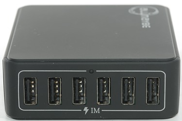
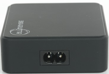
The black surface is lightly rubberized.
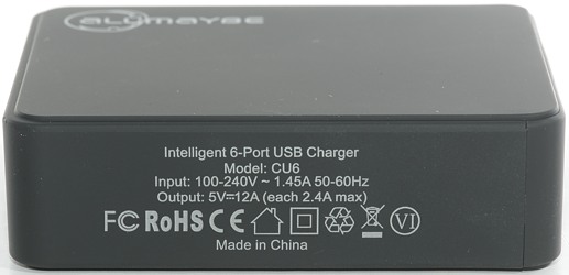
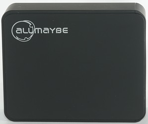
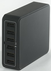
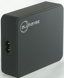
Measurements
- Power consumption when idle is 0.08 watt (Very good)
- All usb output is coded as auto coding with Apple 2.4A as maximum.
- All usb outputs are in parallel.
- There is a blue led between the usb ports.
- Weight without any accessories or mains cable is 204 grams.
- Size is 99x80x28mm
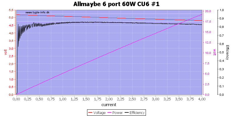
Stable output at any current and a very high efficiency, but it do not look like there is any individual port protection.
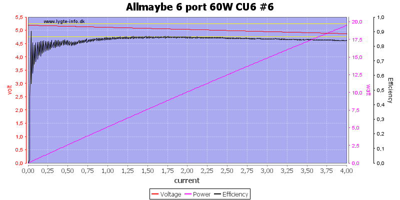
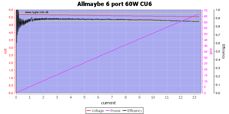
Running all port in parallel I could draw just above 13A before the overload protection kicked in, this is a good limit for a 12A charger.
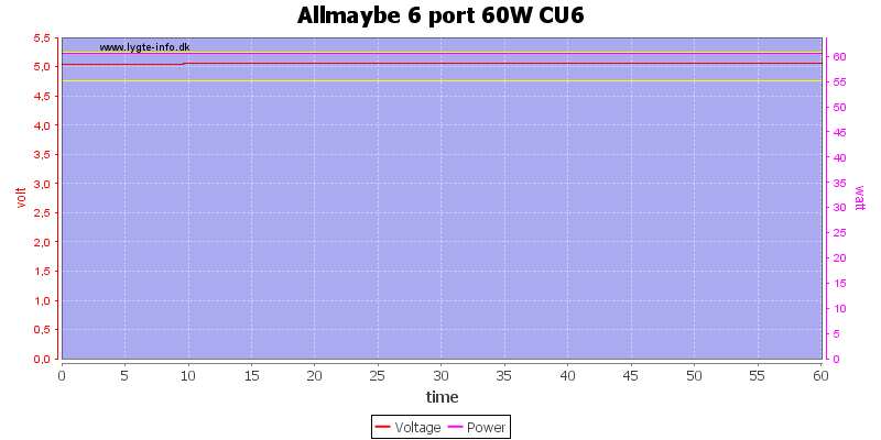
And the charger can deliver 12A for one hour.
The temperature photos below are taken between 30 minutes and 60 minutes into the one hour test.
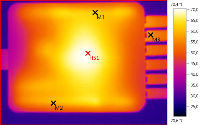
M1: 61,9°C, M2: 59,0°C, M3: 55,5°C, HS1: 70,4°C
At 12A the charger get fairly warm, but not too hot.
HS1 is the mains transformer. M1 and M2 is the two heat sinks.
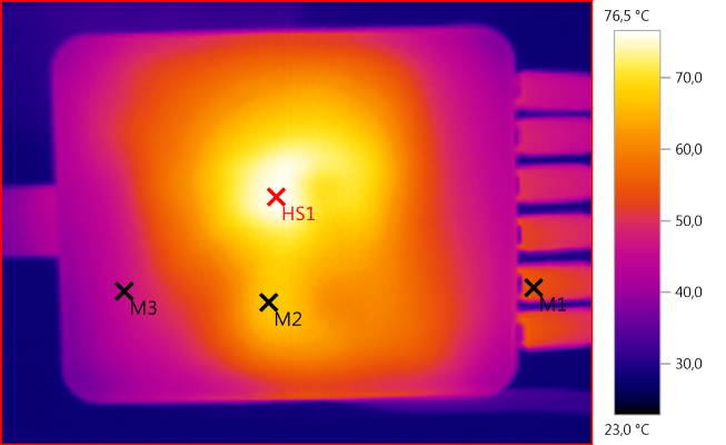
M1: 54,4°C, M2: 67,0°C, M3: 45,7°C, HS1: 76,5°C
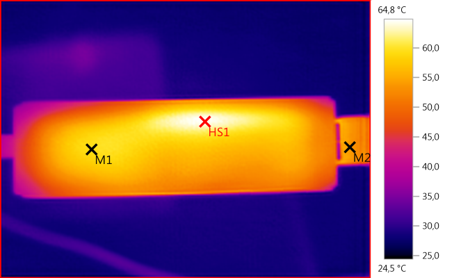
M1: 59,5°C, M2: 54,0°C, HS1: 64,8°C
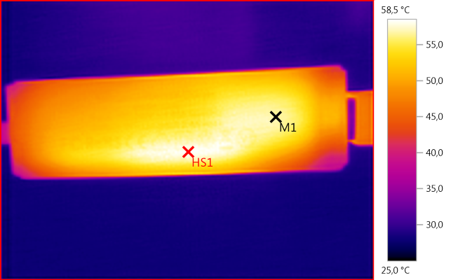
M1: 56,8°C, HS1: 58,5°C
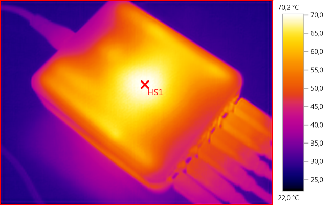
HS1: 70,2°C

At 0.5A the noise is 6mV rms and 104mVpp.

At 1A the noise is 8mV rms and 98mVpp.

At 2.5A the noise is 13mV rms and 132mVpp
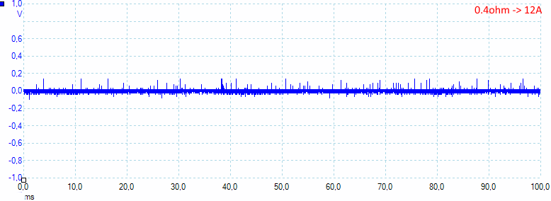
At 12A the noise is 21mV rms and 240mVpp
Tear down
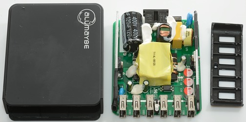
A few hard whacks with my mallet on it and the front popped off.
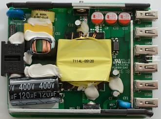
It looks like a nice layout and very few parts for this powerhouse of a charger.
At the input there is a fuse (F1), the blue disc (RV1:MOV) is overvoltage protection. Then we have a common mode coil, a capacitor (CX) and one more common mode coil (Looks like a fairly decent noise filter). Under the white stuff is a bridge rectifier. On the heatsink (HS1) is the mains switcher transistor (Q1). Close to the heatsink is the safety capacitor (CY1) and a NTC (NTC1), this is probably used to shut down the electronic if it gets too hot (Very nice). Besides the transformer is opto feedback (U2).
On the low voltage side there is the synchronous rectifier (Q8), between the 6 usb connectors the blue led can be seen.
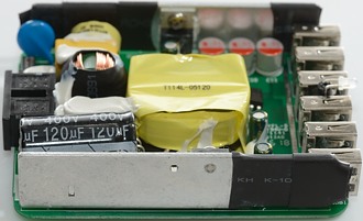
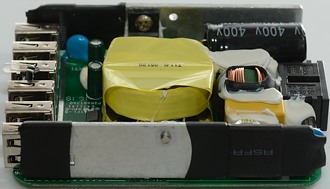
The heat shrink on the heatsinks are used for isolation.
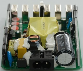
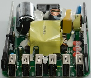
Besides the mains input is the black fuse and the blue MOV.
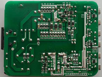
Most of the IC's are on this side. The mains switcher has many components in parallel, both resistors and diodes, this is usual done to increase power/current handling capability, without using larger parts.
The mains switcher is U1 (Marked 675S9) and placed very close to Q1. It looks like some rework has been done around here.
On the low volt side we have the synchronous rectifier controller (U5), voltage reference (U3 TL431),
At last we have the auto coding chips (U4, U6, U7, RH7902B).
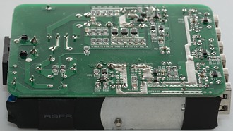
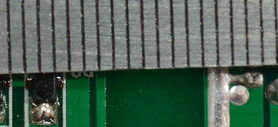
Creepage distance is above 6mm.
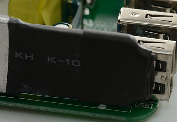
The heatsinks are isolated with double layer heat shrink where it has to withstand mains voltage.
Testing with 2500 volt and 5000 volt between mains and low volt side, did not show any safety problems.
Conclusion
This is a very good charger for charging many phones or pads at once, it can handle 5 or 6 pads at a time. The output voltage is stable, it will automatic select the coding to get as fast charge as possible, noise is very low, the efficiency is good and the temperature is acceptable.
I like the charger, but I will only give it a good rating, because it is missing individual port protection (Most multi-port charges has this problem).
Notes
The usb charger was supplied by Allmaybe for a review.
Read more about how I test USB power supplies/charger


