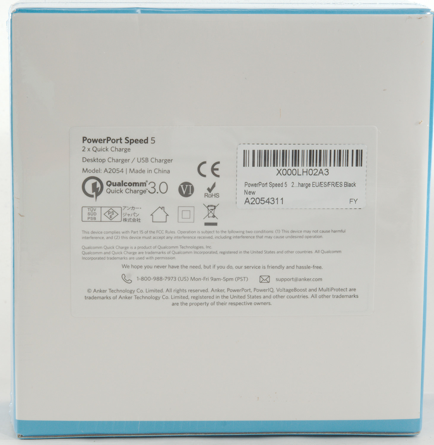
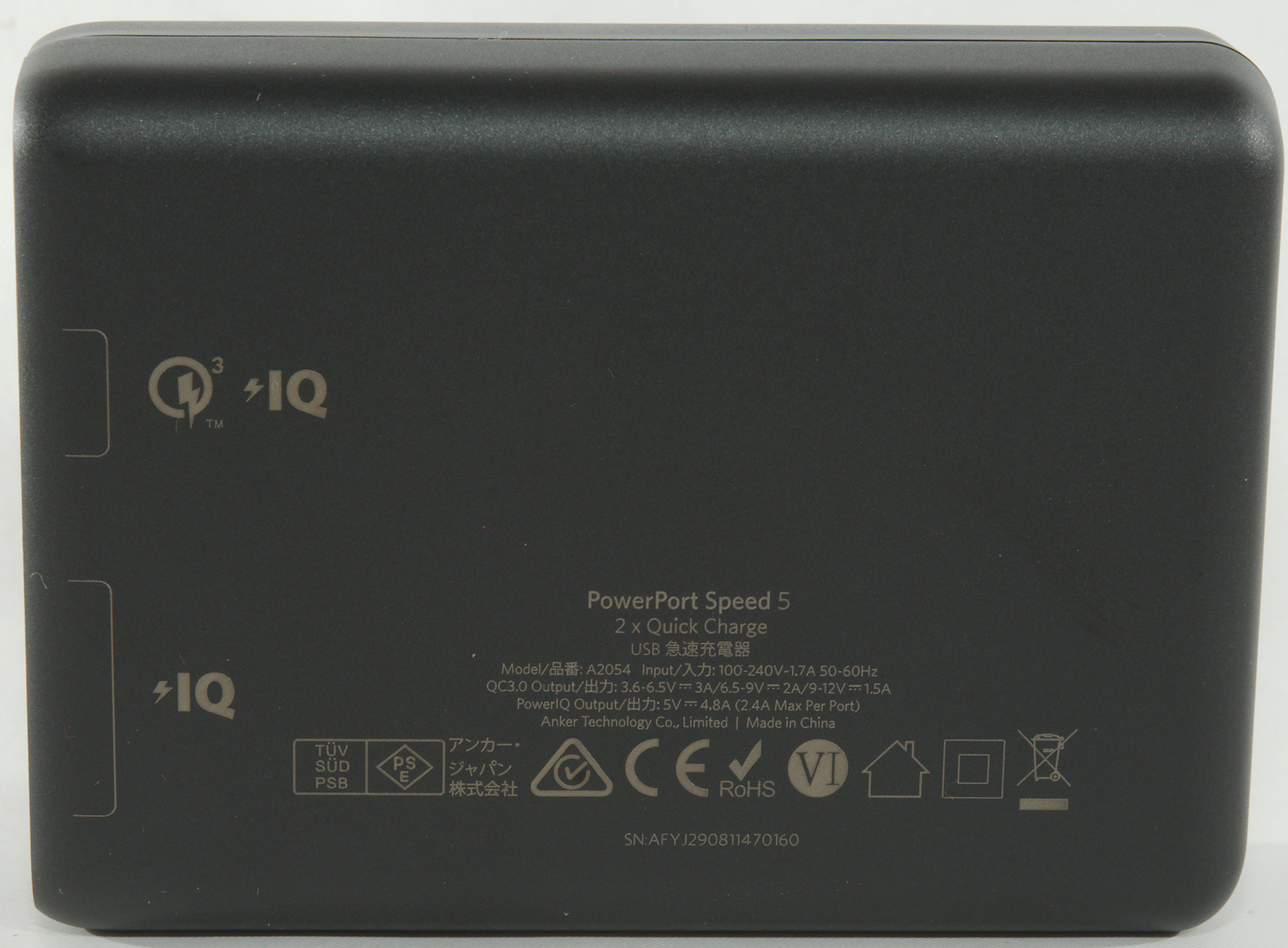
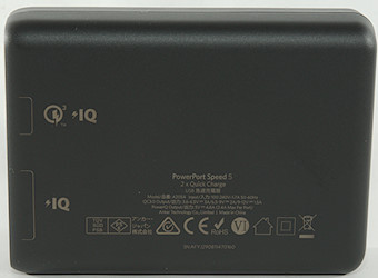
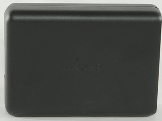
Anker PowerPort Speed 5 2xQC3 A2054
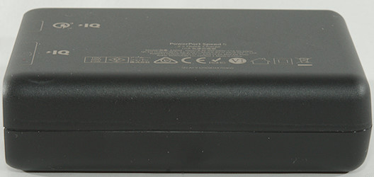
Official specifications:
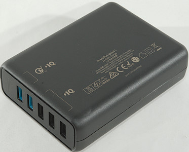
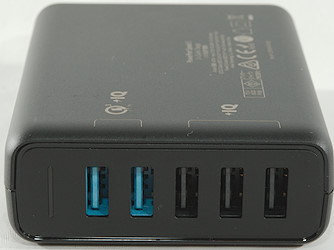
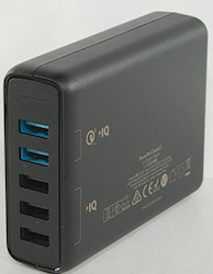
- Charging Ports: 5
- Wattage : 63W
- Output Currency: 3.6V-6.5V / 3A, 6.5V-9V / 2A, 9V-12V / 1.5A
- Size: 10.2 x 7.5 x 2.8 cm
- Weight: 295 g
I got it from a amazon.de dealer: AnkerDirect DE

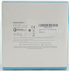
I got it in a cardboard box.
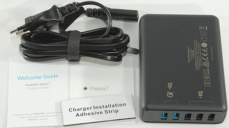
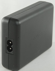
The box included the charger, a mains cable, a welcome guide (Instruction sheet) and a adhesive strip to mount the charger somewhere.
Measurements
- Power consumption when idle is 0.2 watt
- 2.4A USB outputs is auto coding with DCP, Samsung, QC5V, Apple 2.4A
- QC USB output is auto coding with QC3, DCP, Apple 2.4A, Huawei-FCP
- Minimum QC3 output is 3.6V
- 2.4A outputs are in parallel.
- QC and 2.4A outputs share minus connection.
- Weight: 222g without mains cable
- Size: 102 x 74.7 x 29mm
The output has cable compensation, but it only works below 1A and there is no individual port protection.
This output looks the same.
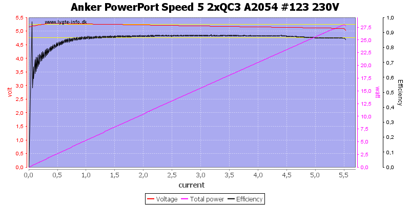
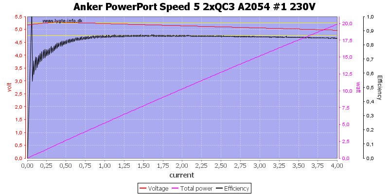
Running all 3 2.4A output in parallel I can see the overload protection is at around 5.5A, this is a high current for a single usb port (Will happen if a cable is shorted).
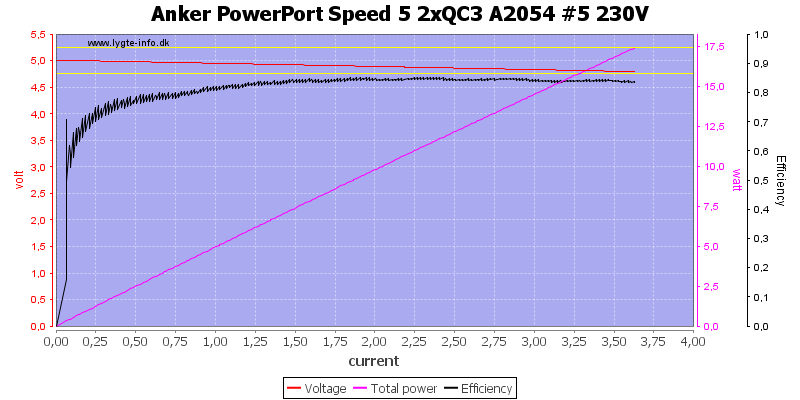
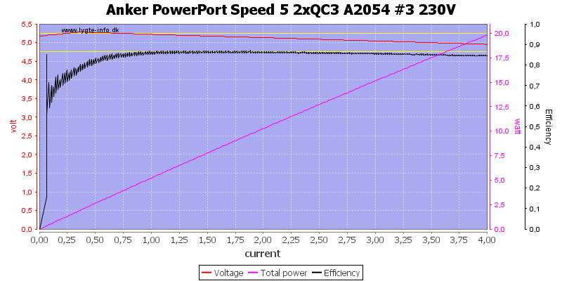
At 5V the QC port can deliver about 3.5A (I did run this test on both QC port, they are very similar).
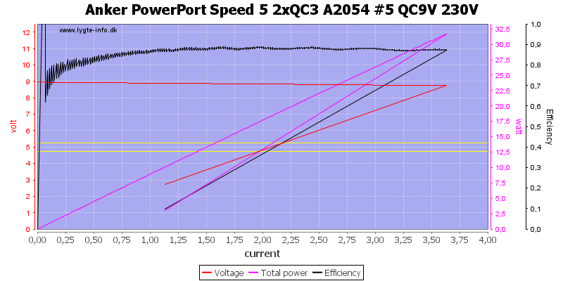
This also holds at 9V
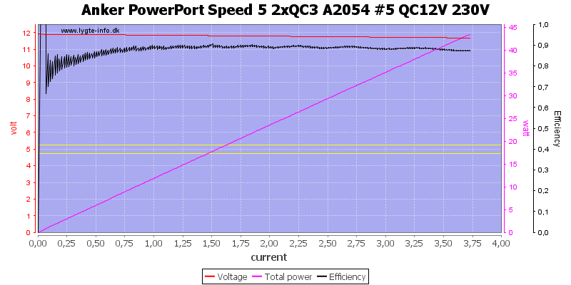
And even at 12V
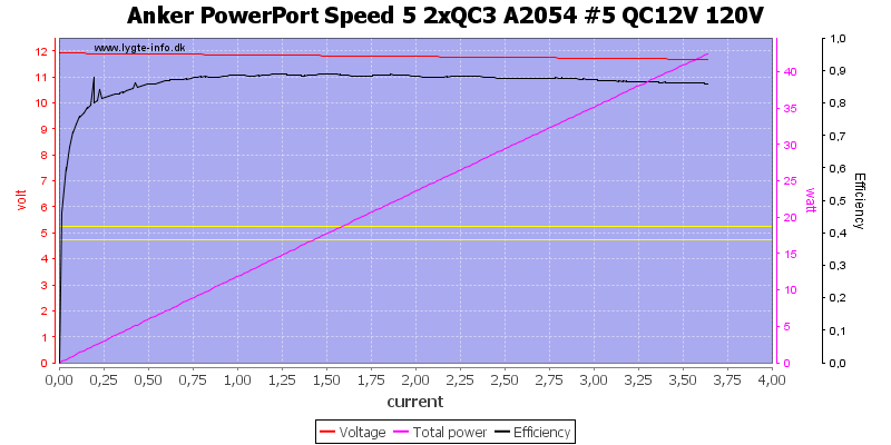
Using 120VAC do not change it.
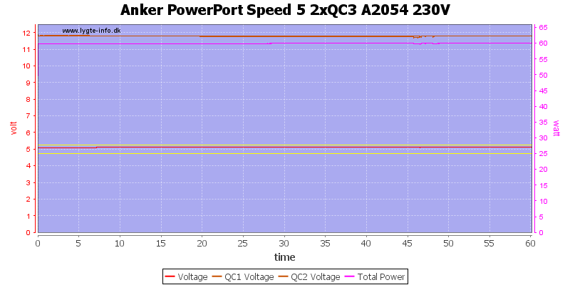
For load test I did 5V 4.8A and 2x12V 1.5A
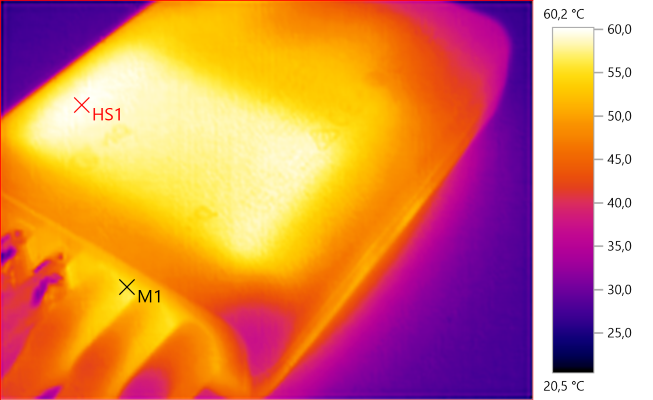
The temperature photos below are taken between 30 minutes and 60 minutes into the one hour test.
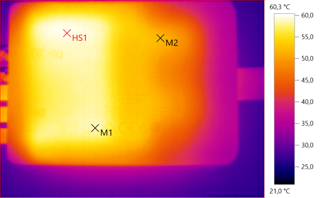
M1: 58.5°C, M2: 51.6°C, HS1: 60.3°C
The heat profile matches the heatsink below (See tear-down). HS1 and M1 are the two transformers (HS1 is QC).
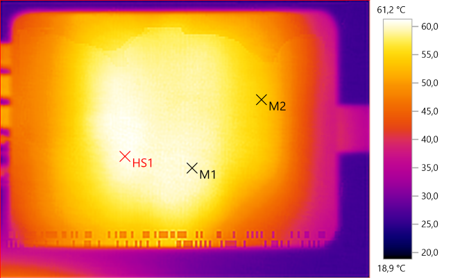
M1: 59.8°C, M2: 54.5°C, HS1: 61.2°C (The "Barcode" is a fault from my camera or memory card, this is the only time I have seen it).
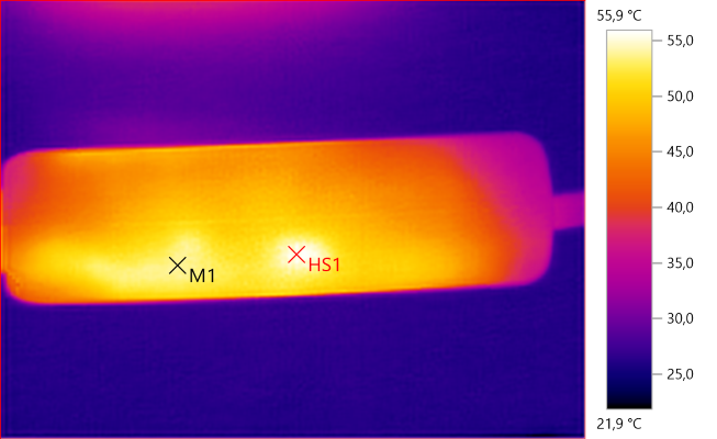
M1: 53.9°C, HS1: 55.9°C
HS1 is one of the mains switchers.
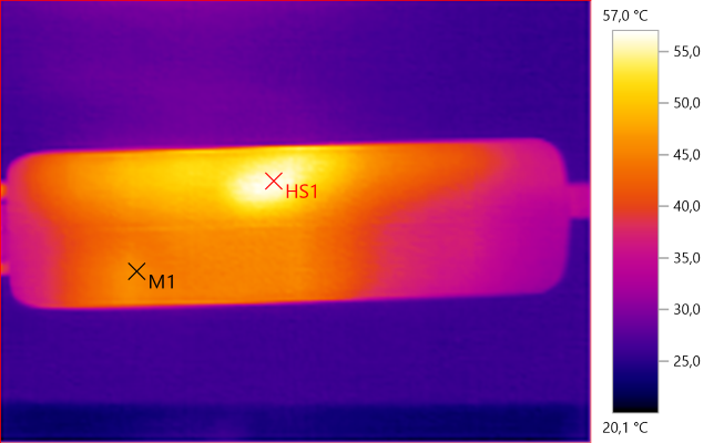
M1: 45.6°C, HS1: 57.0°C
Again HS1 is one of the mains switchers.
M1: 55.3°C, HS1: 60.2°C
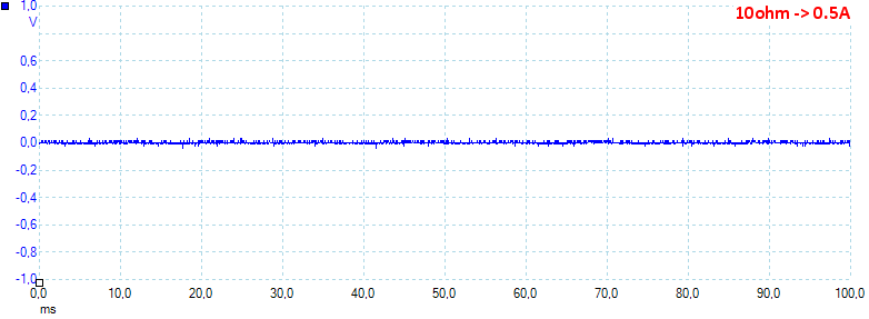
Noise at 0.5A load is: 15mV rms and 126mVpp.
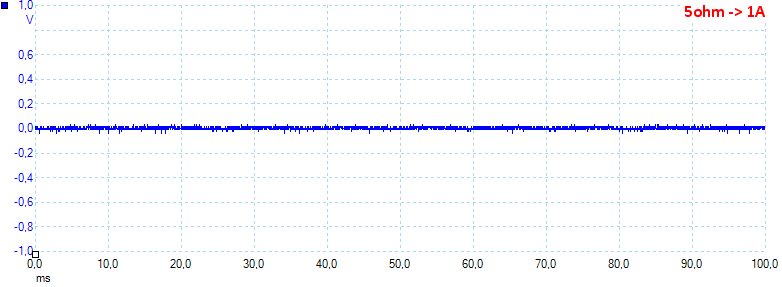
Noise at 1A load is: 14mV rms and 244mVpp.
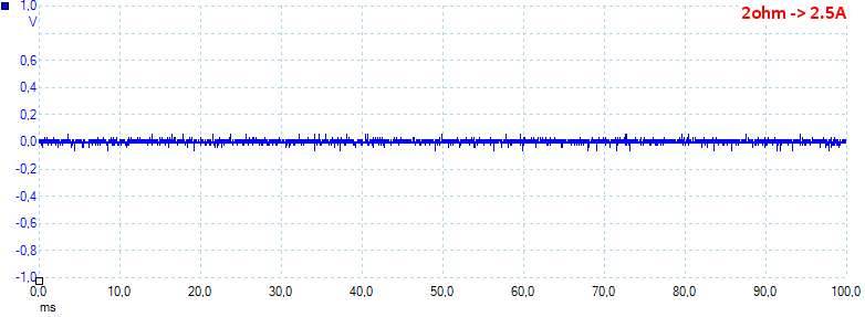
Noise at 2.5A load is: 12mV rms and 152mVpp.
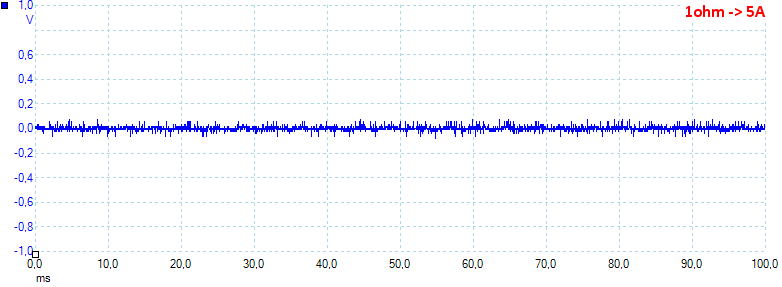
Noise at 5A load is: 14mV rms and 163mVpp.
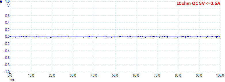
Noise at 0.5A QC load is: 4mV rms and 99mVpp.
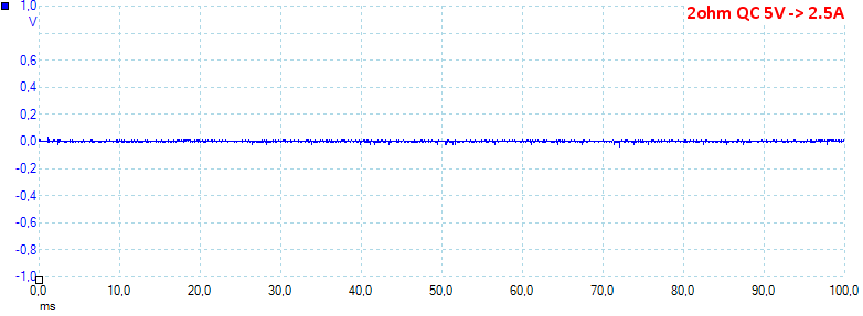
Noise at 2.5A QC load is: 10mV rms and 205mVpp.
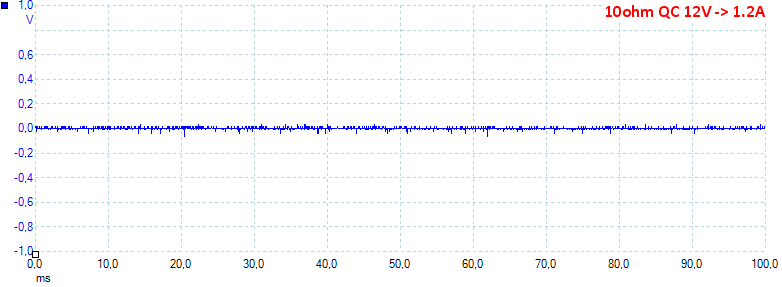
Noise at 12V 1.2A QC load is: 5mV rms and 118mVpp, all values are very low.
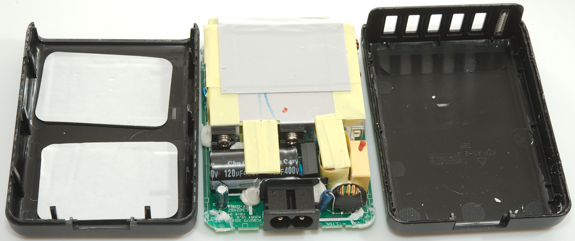
Tear down
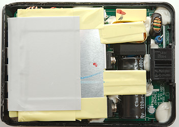
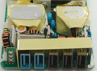
Some pressure with my vice and I could break the lid of with a screwdriver. The circuit board did not come loose, it is secured with a bit of glue.
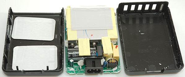
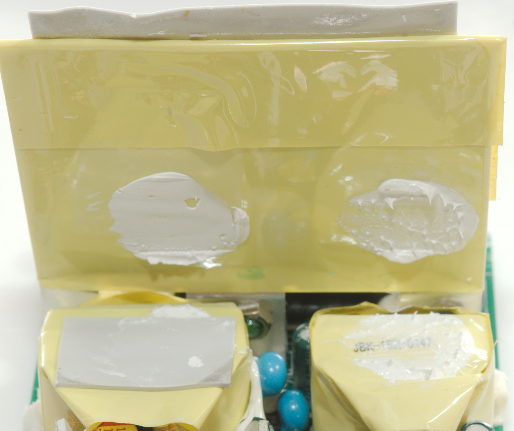
A bit more breaking and it was out, notice the white pads on the lid, they are to improve heat transfer.
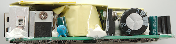
The transformers is very close to the top heatsink.
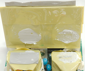
And there is some heat transfer paste between transformer and heatsink.
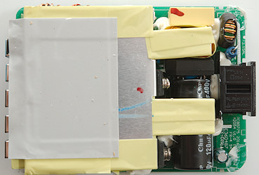
The heatsink is covered in yellow tape for isolation and a gray heat transfer pad.
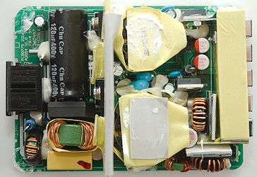
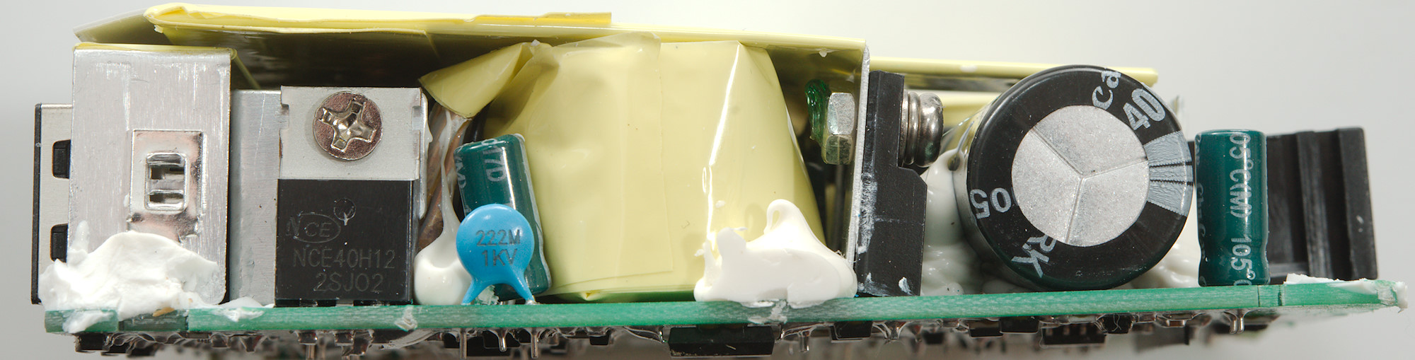
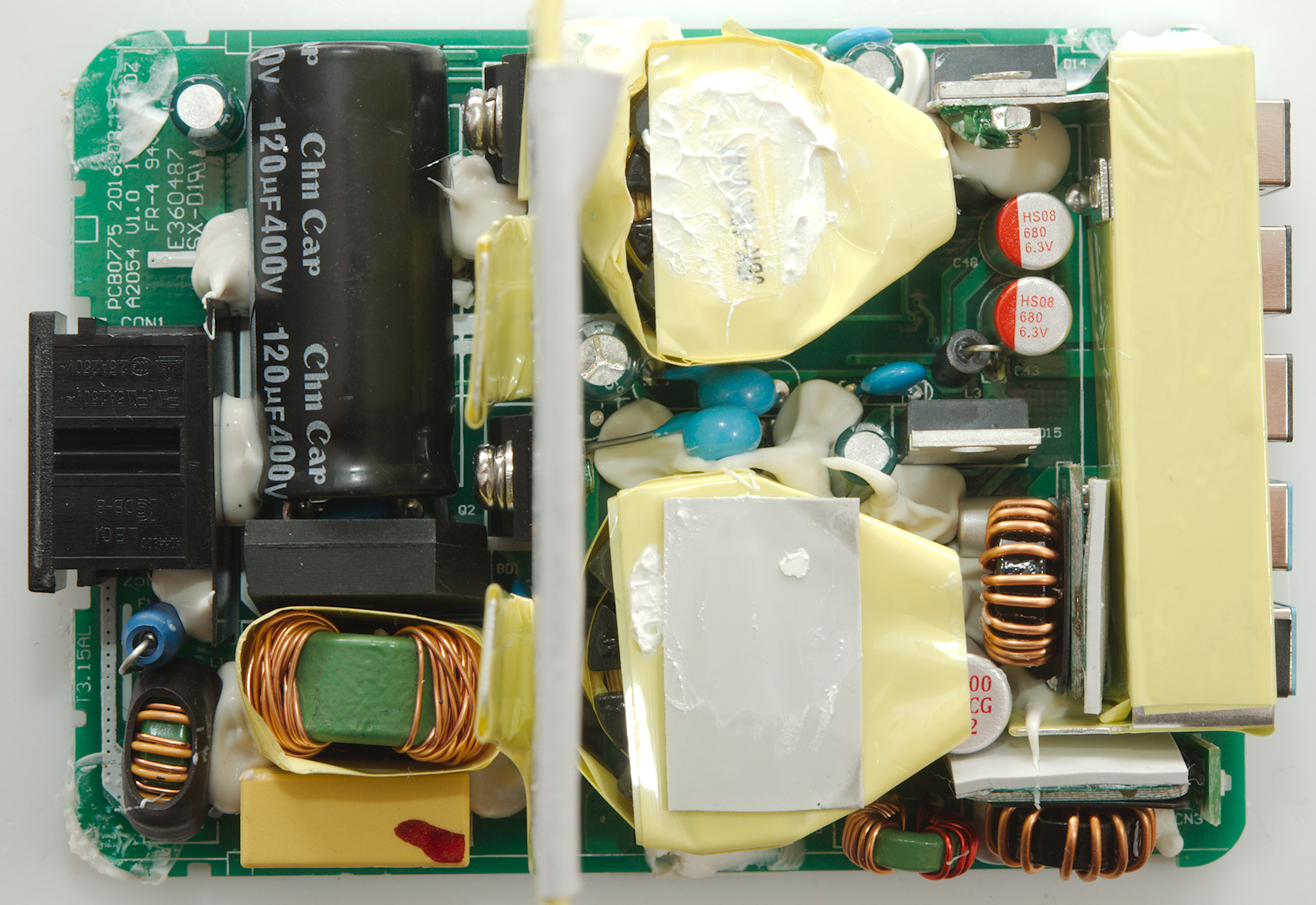
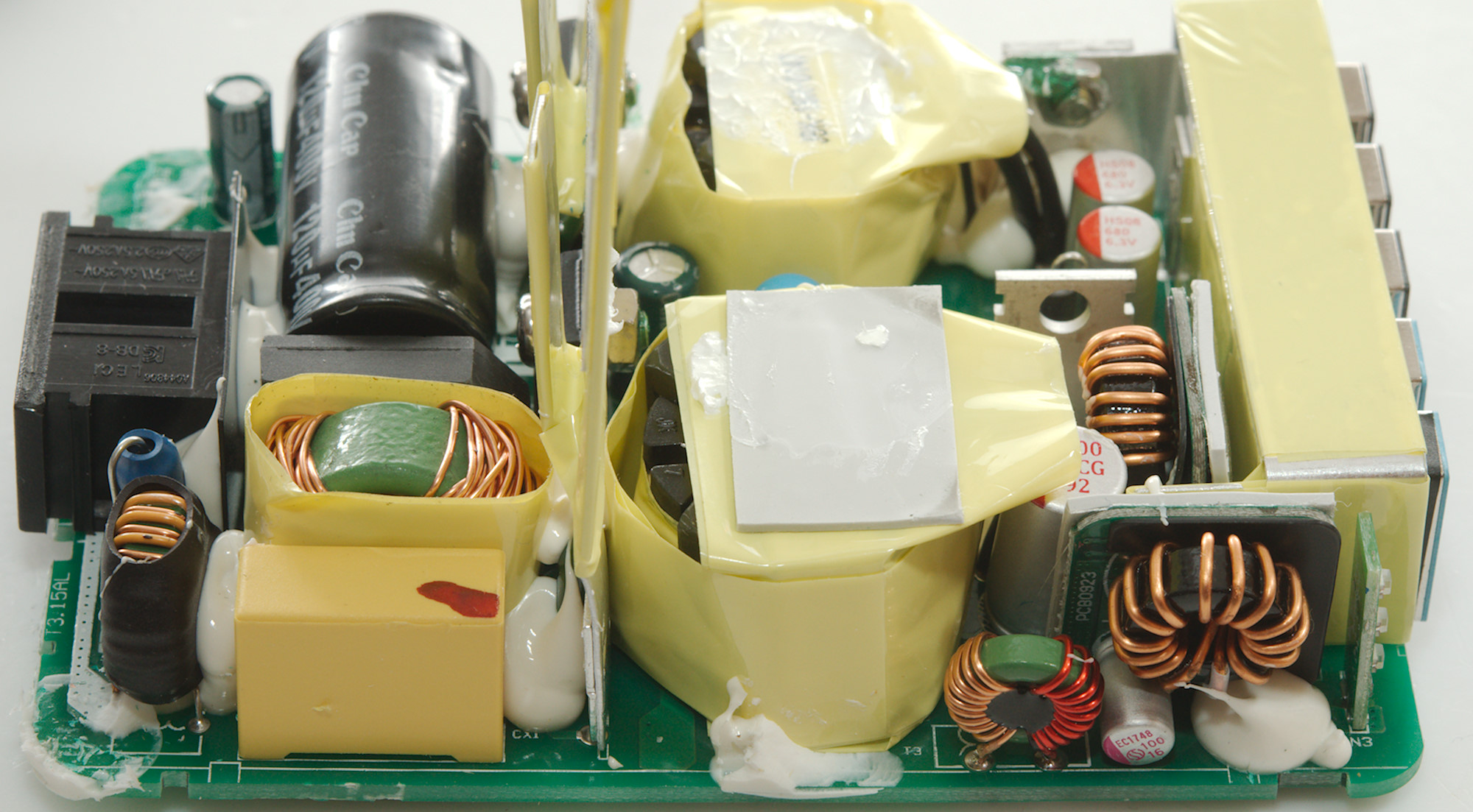
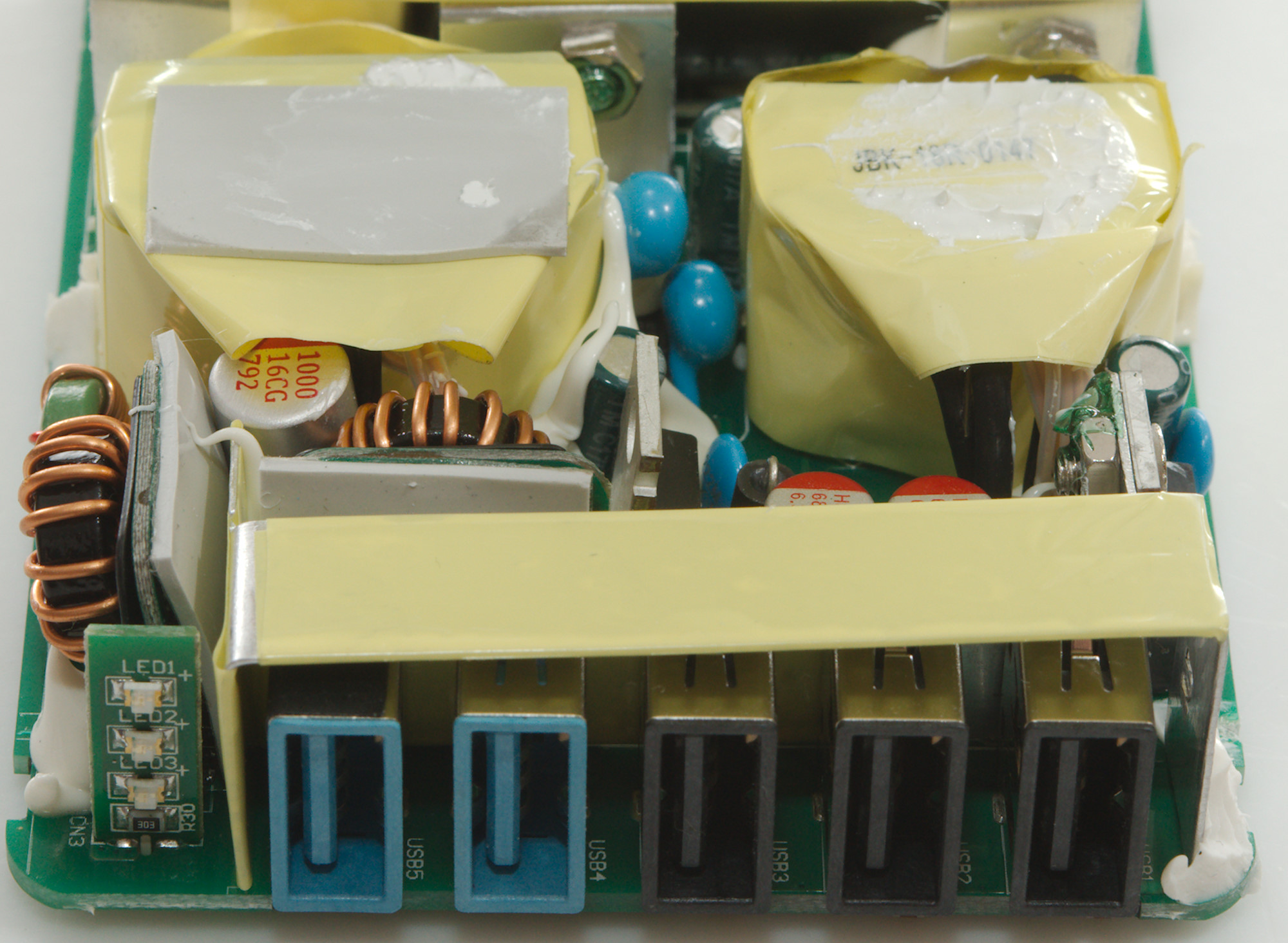
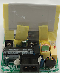
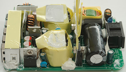
At the mains input is a fuse (F1) and two common mode coils (L1, ?) followed by a bridge rectifier (BD1). There are two mains switcher transistors on for 5V 2.4A and one for 2xQC (Q2). Between the two transformers are two safety capacitors and one opto-coupler for QC.
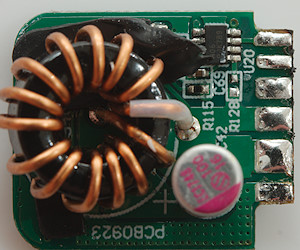
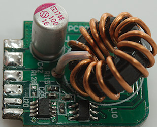
One the low volt side are two rectifier transistors (Q14 & Q15, synchronous rectification). The QC outputs shares a common mode coil and there is a inductor for each, they are mounted on two small circuit boards with the a QC controller each. There is also a small circuit board with 3 leds for the indicator on the front.
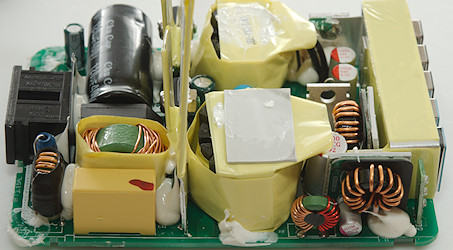
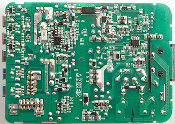
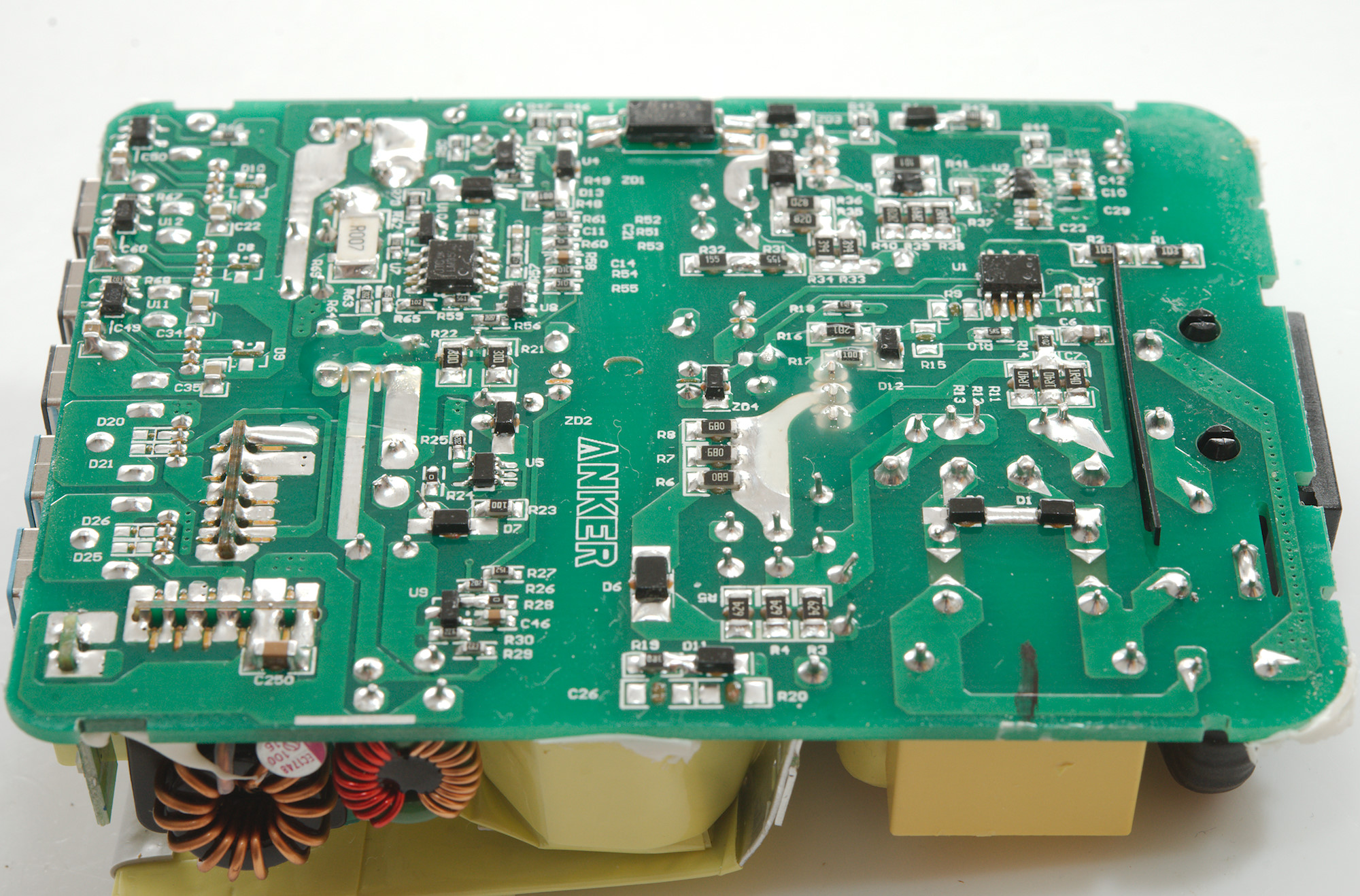
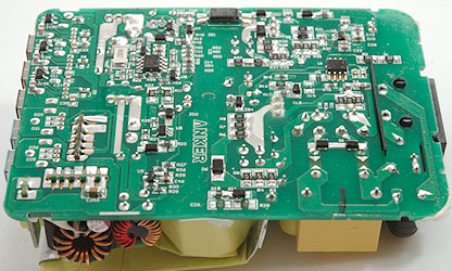
With two transformers there must also be two switch mode controllers (U1 & U2). The opto-coupler for 5V is on this side (U3). For the 5V 2.4 outputs there is a synchronous rectifier controller (U4), a OpAmp (U7) together with a resistor (R69: 0.007ohm) to add the cable compensation to the reference (U8 and/or U10). Each of the 3 2.4A usb output has a auto coding chip (U11, U12, U13: probably CW3002).
The QC contains a 14.1V power supply that has a synchronous rectifier controller (U5) and a voltage reference (U9).
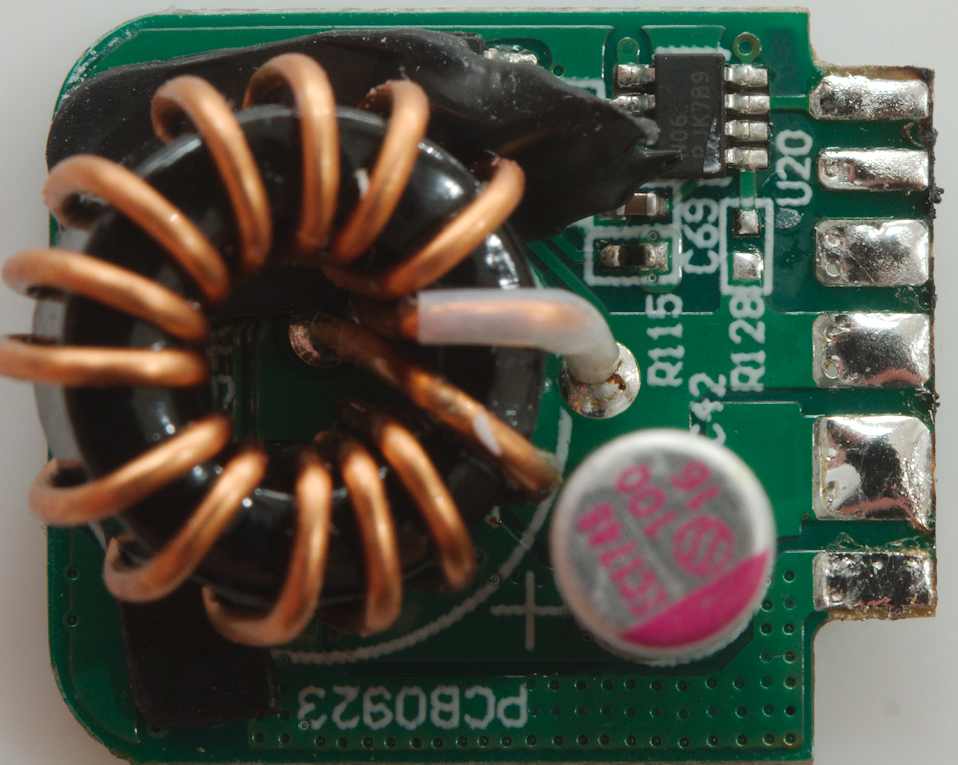
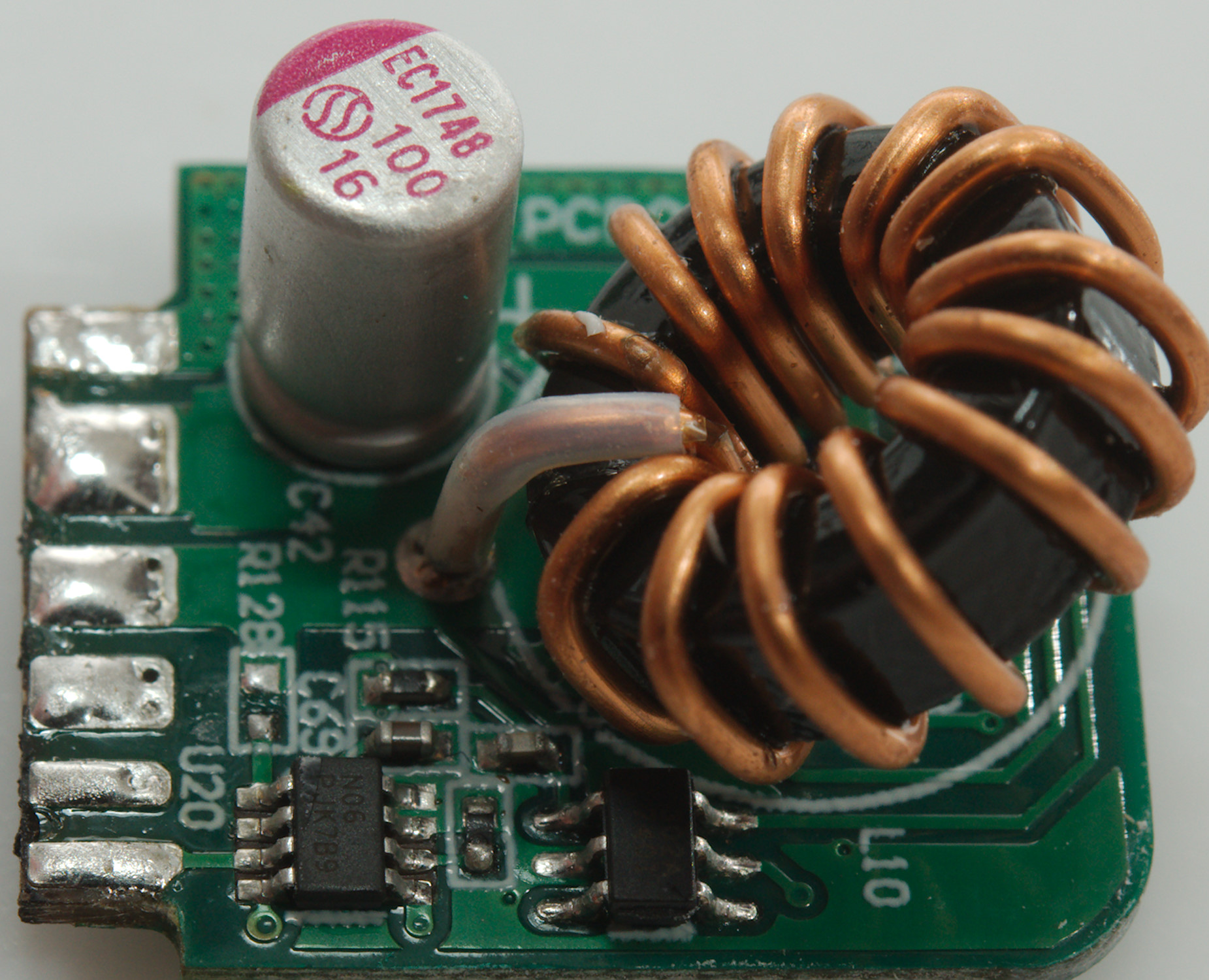
The actual QC controllers are on other circuit board that are soldered in slots with 6 connections on each side.
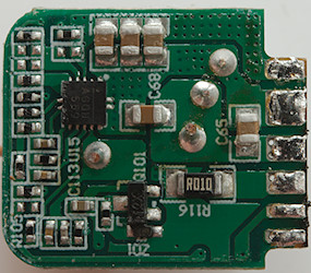

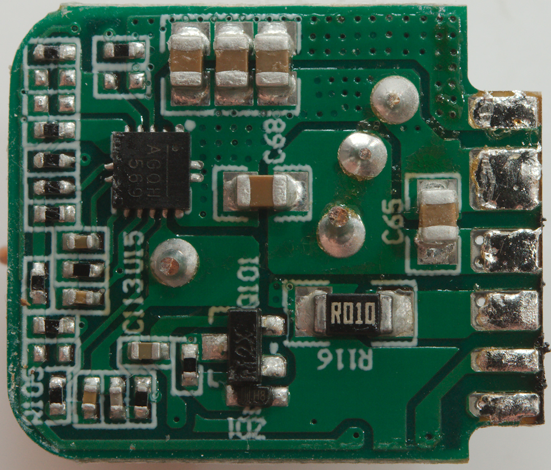
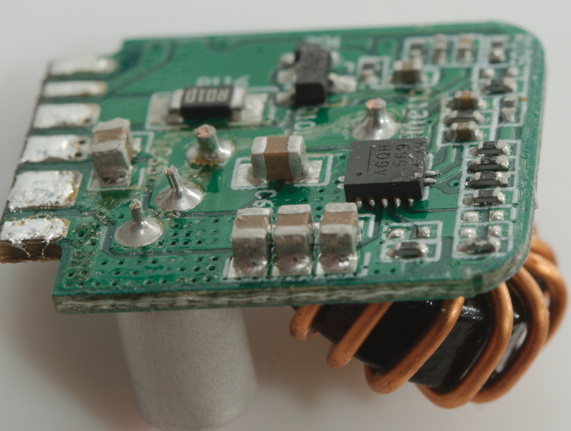
The square chip (U15: marked AGQH569) is probably the buck converter.
The QC controller is here (U20: Marked PJK789)
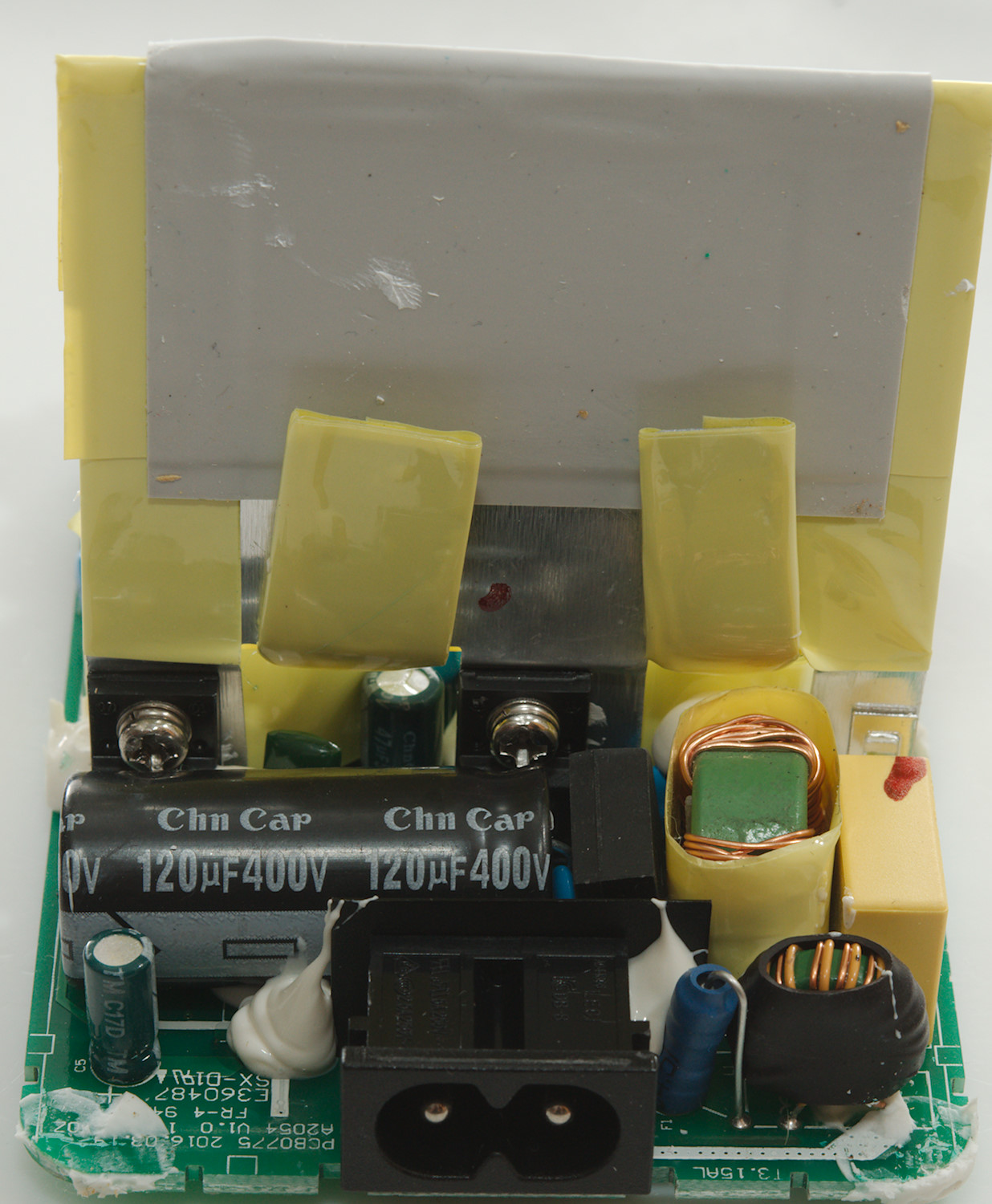
There is more than enough distance between mains and low volt side.
Testing with 2830 volt and 4242 volt between mains and low volt side, did not show any safety problems.
Conclusion
This is a good charger with lots of output current (It can fast charge 4 devices at a time), it has auto coding, low noise and two Quick Charge outputs.
Notes
Index of all tested USB power supplies/chargers
Read more about how I test USB power supplies/charger
How does a usb charger work?