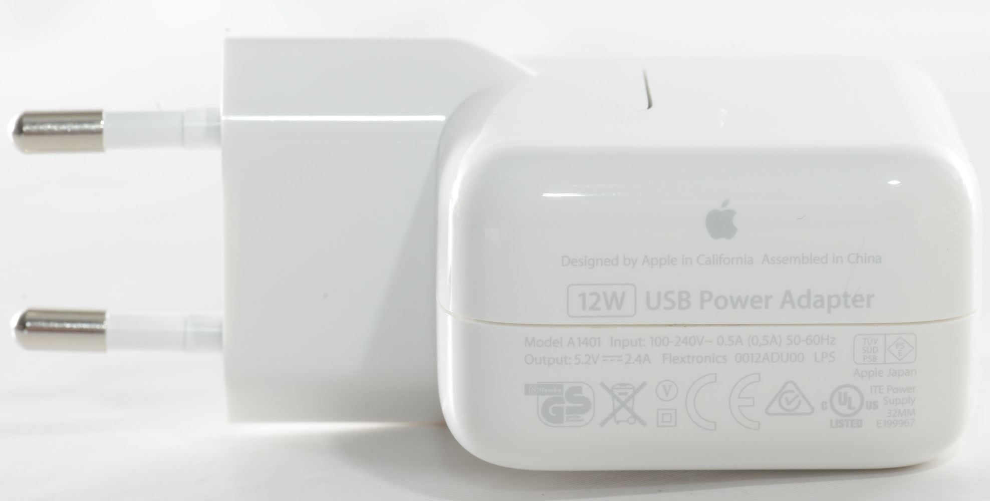
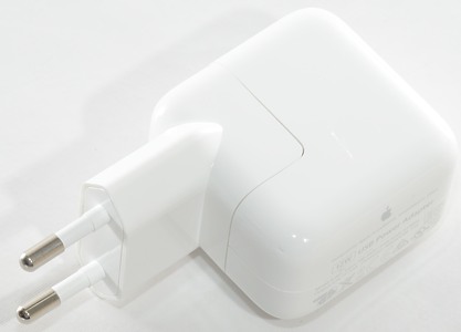
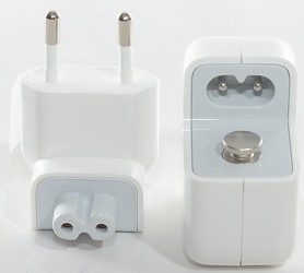
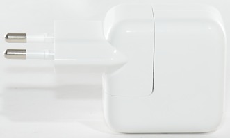
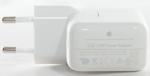
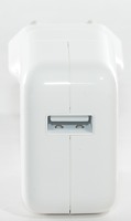
Apple 12W USB power adapter model A1401
Official specifications:
- 12 watt USB power adapter
- Compatible with iPad, iPhone and iPod
- Output: DC 5.2V, 2.4A
- Input: AC 100-240V 50/60Hz
I bought this in the Apple webshop, this way I know it is not a fake.
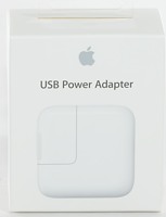
I got this charger in a cardboard box with a picture of the charger on the outside.
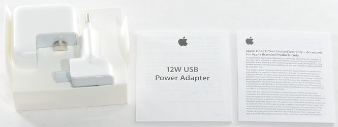
The box contained the charger, manual and warranty card.
Measurements
- Standby power: 0.05 watt
- Output is coded as Apple 2.4A
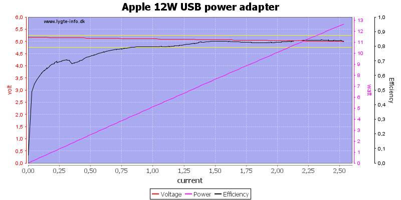
The charger can deliver 2.5A before it shuts down due to overload and has a very good efficiency (Very good).
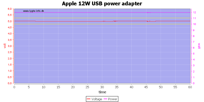
No problem running at 2A for one hour.
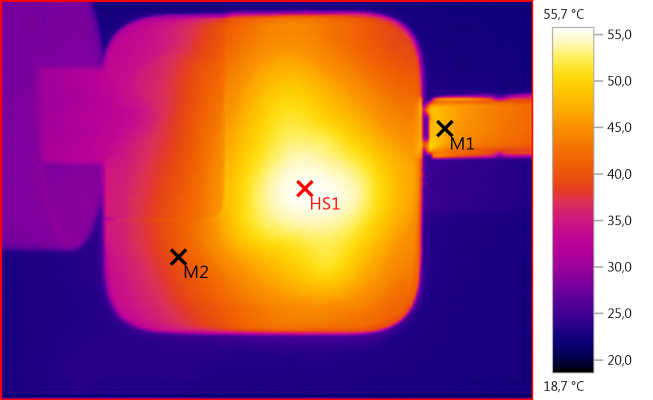
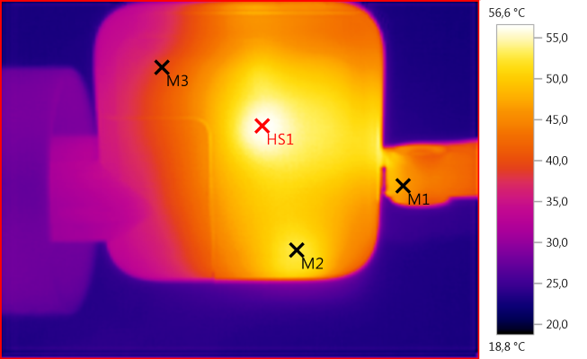
The temperature photos below are taken between 30 minutes and 60 minutes into the 1 hour test.
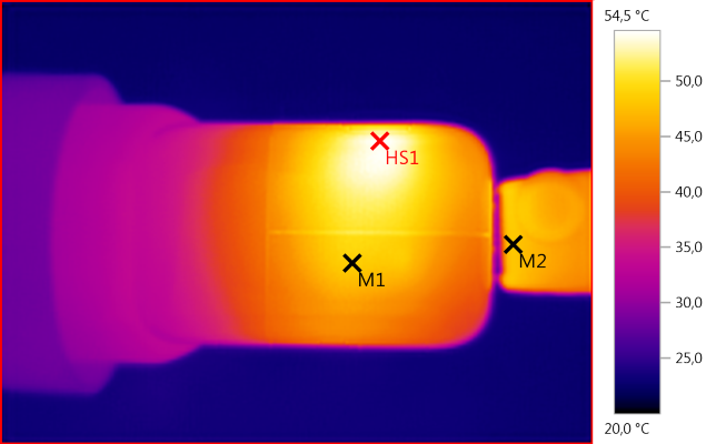
M1: 48,6°C, M2: 48,1°C, HS1: 54,5°C
The hot spot here must be the rectifier diode.
M1: 47,1°C, M2: 40,0°C, HS1: 55,7°C
Here the hot spot is the trafo.
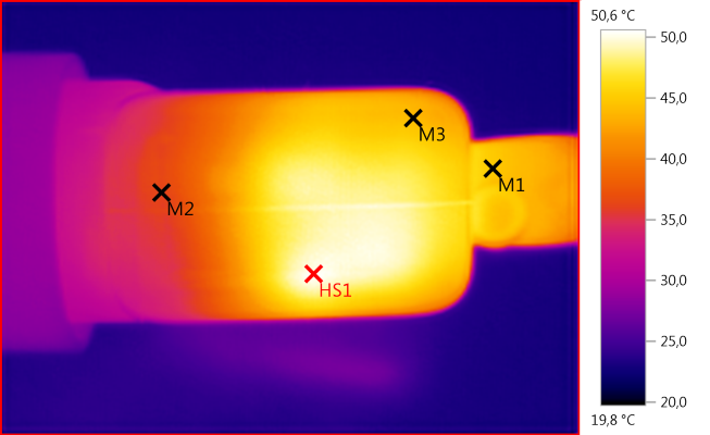
M1: 45,0°C, M2: 36,1°C, M3: 44,0°C, HS1: 50,6°C
M1: 46,6°C, M2: 52,6°C, M3: 39,3°C, HS1: 56,6°C
Here the hot spot matches the switch mode controller.
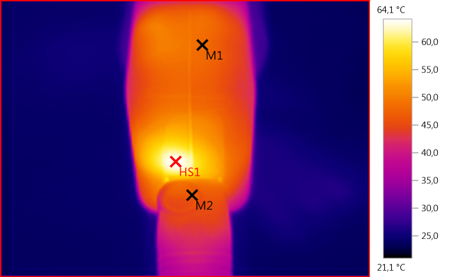
M1: 48,4°C, M2: 46,8°C, HS1: 64,1°C
And the power transistor.
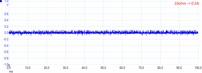
There is not much noise at 0,5A with 21mV rms and 230mVpp
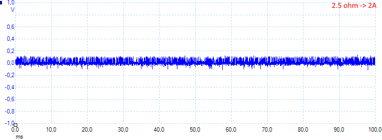
At 2A there is a more noise with 33mV rms and 390mVpp
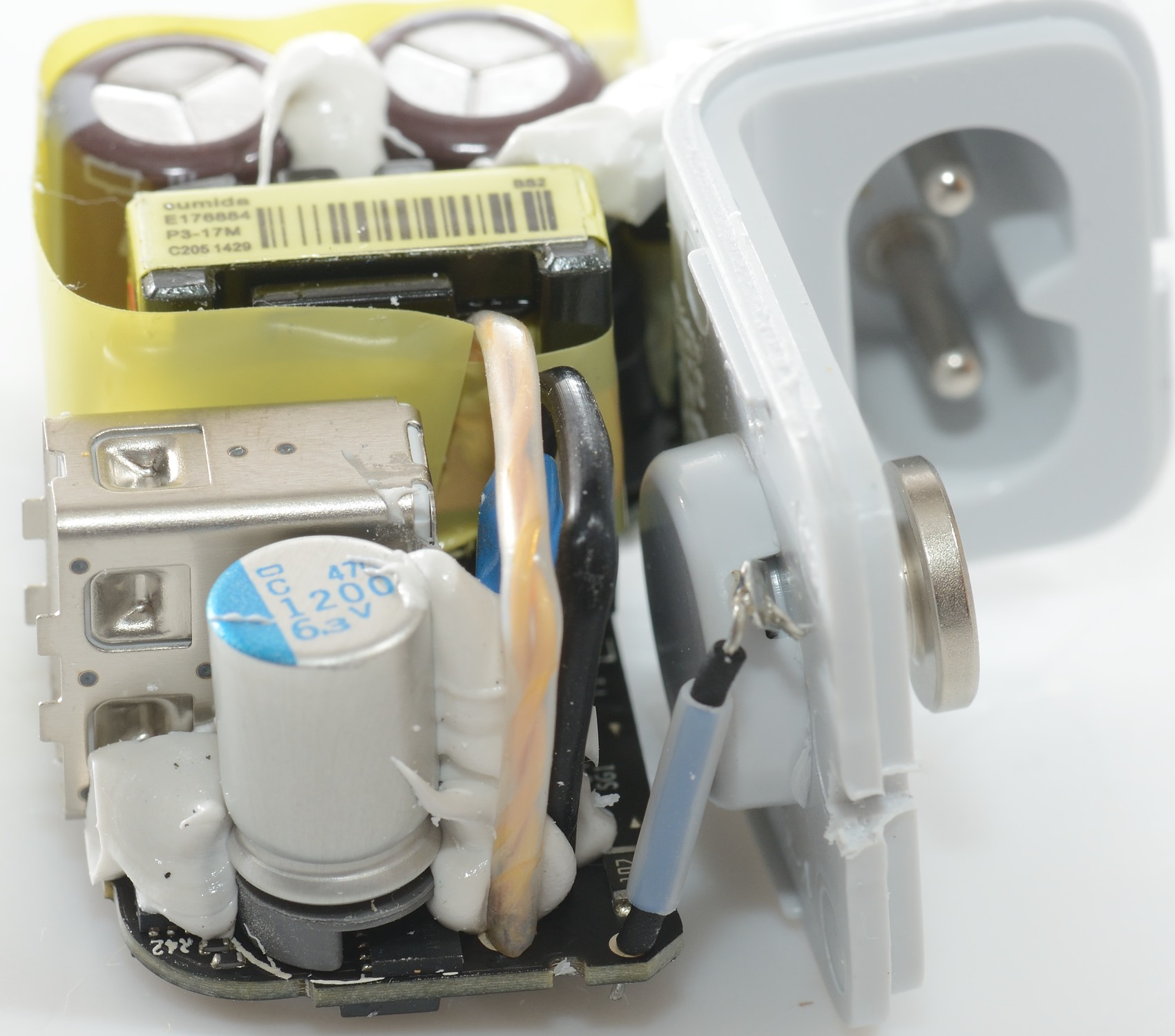
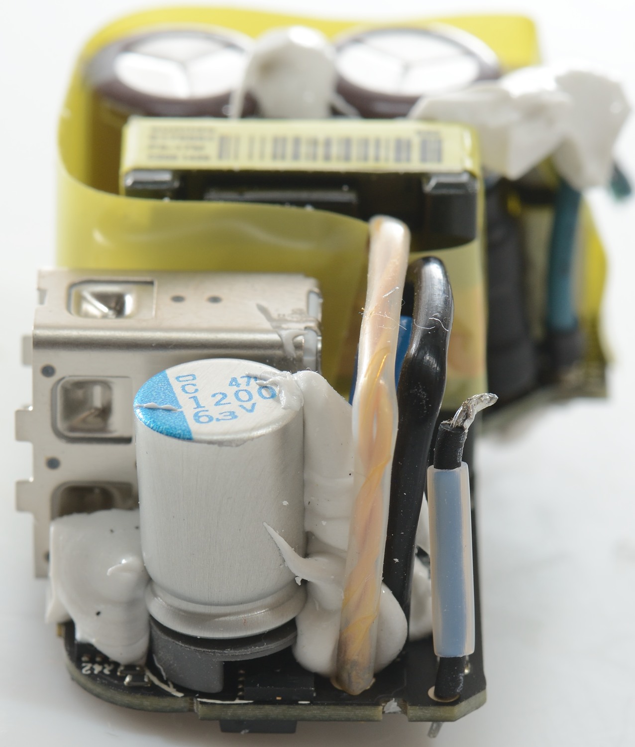
Tear down
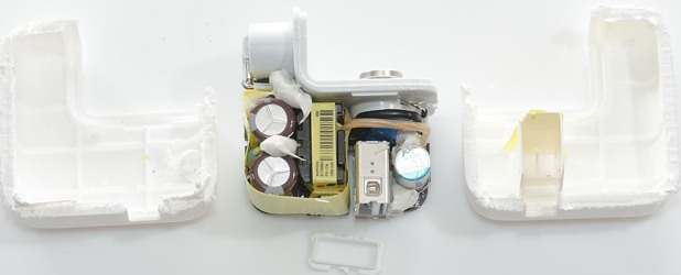
I could not break the charger open and had to cut it.

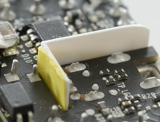
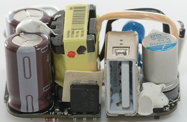
Notice the white plastic shield that goes around the usb connector to improve isolation and mechnical strength.
The metal knot to hold the plug in place is connected inside the circuit, it has 1kOhm to the usb ground.
With the shield fully in, most of the low volt section is isolated from the mains.

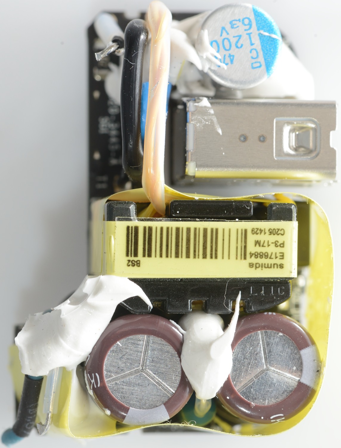
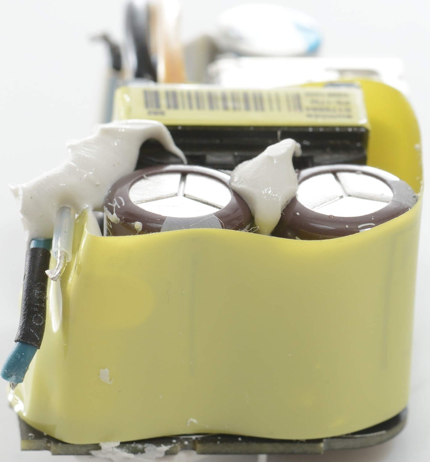
The yellow tape inproves the isolation between the mains input and the mains capacitors.
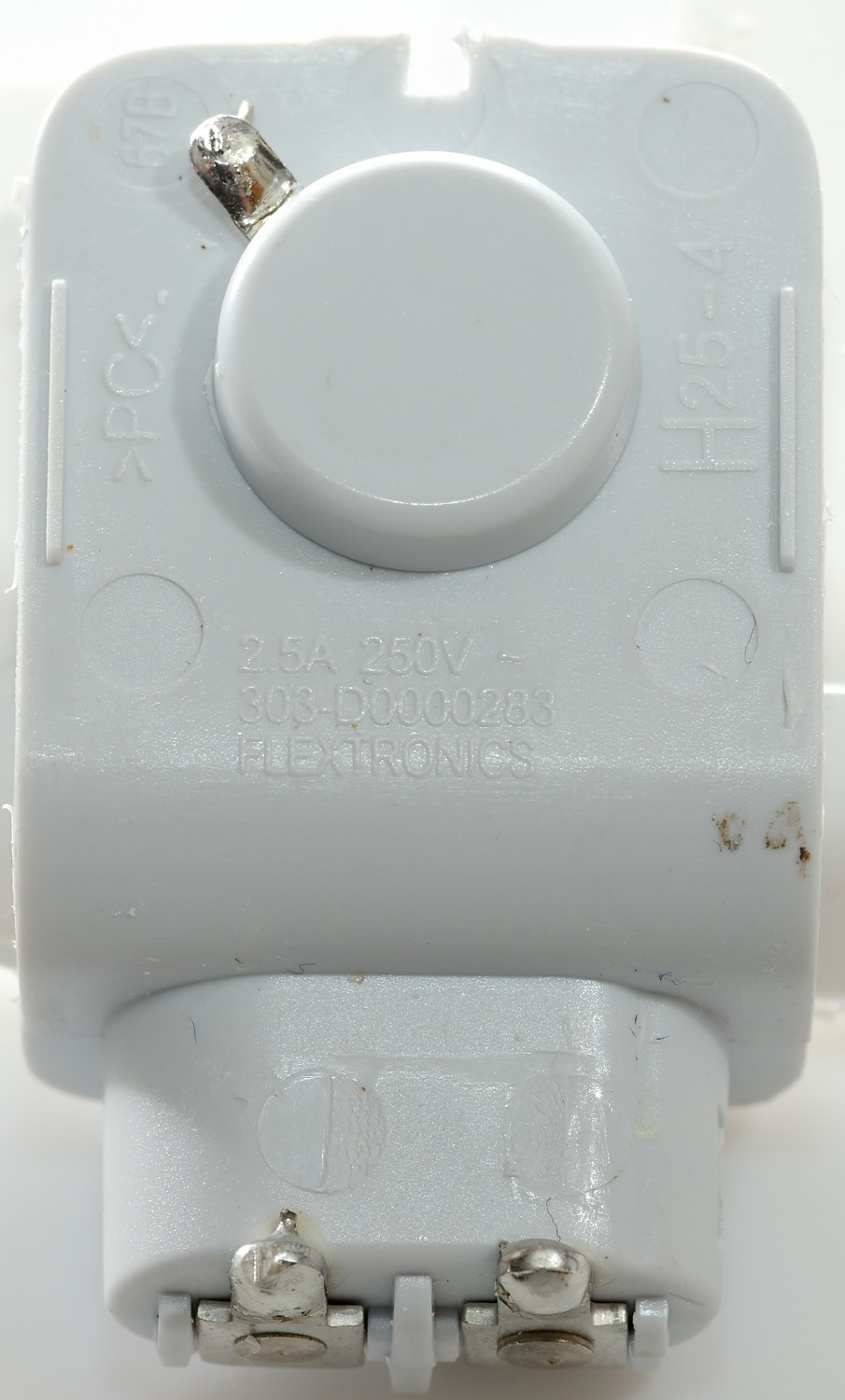
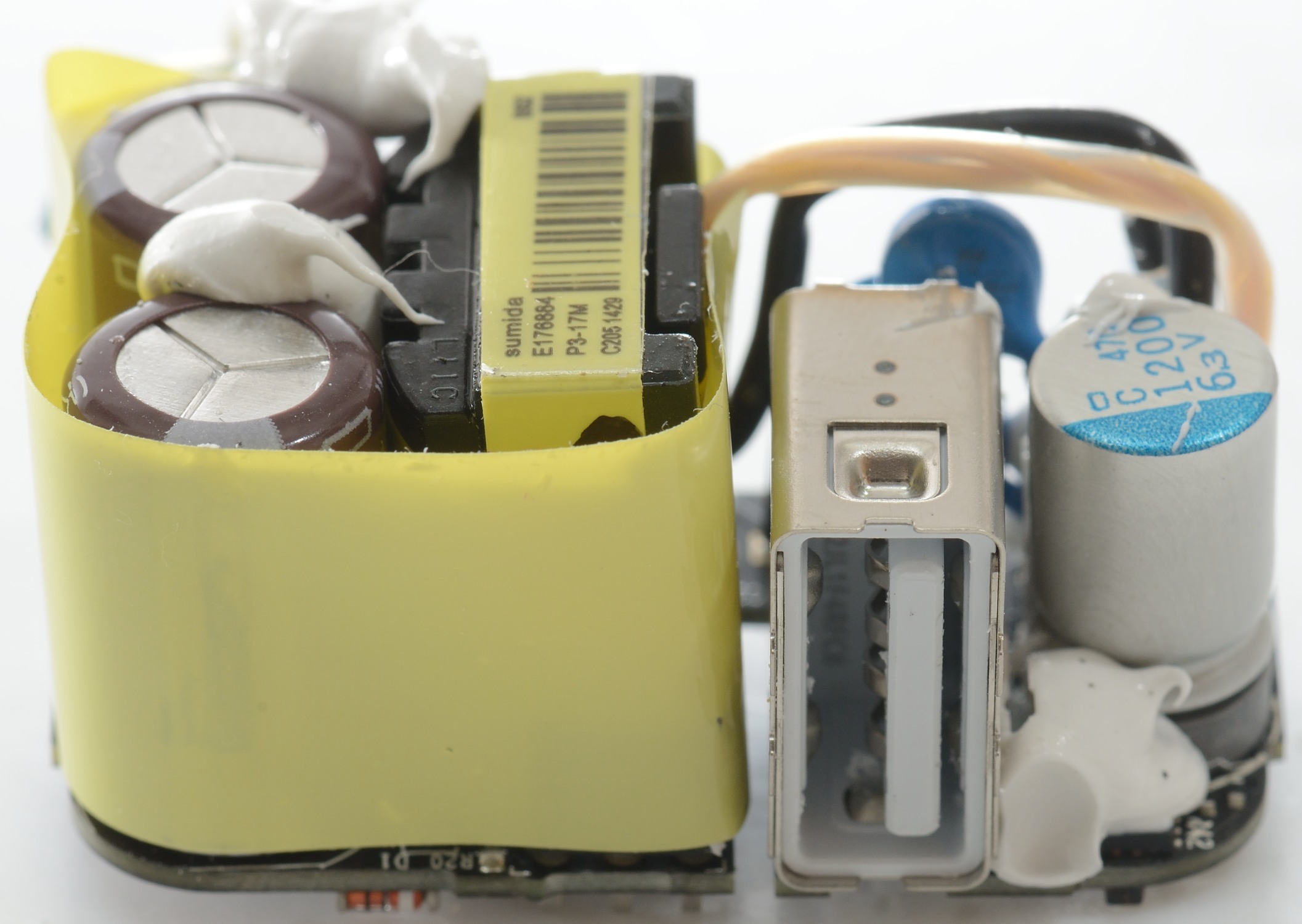
The plastic part is marked on the inside.
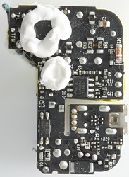
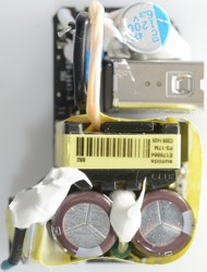
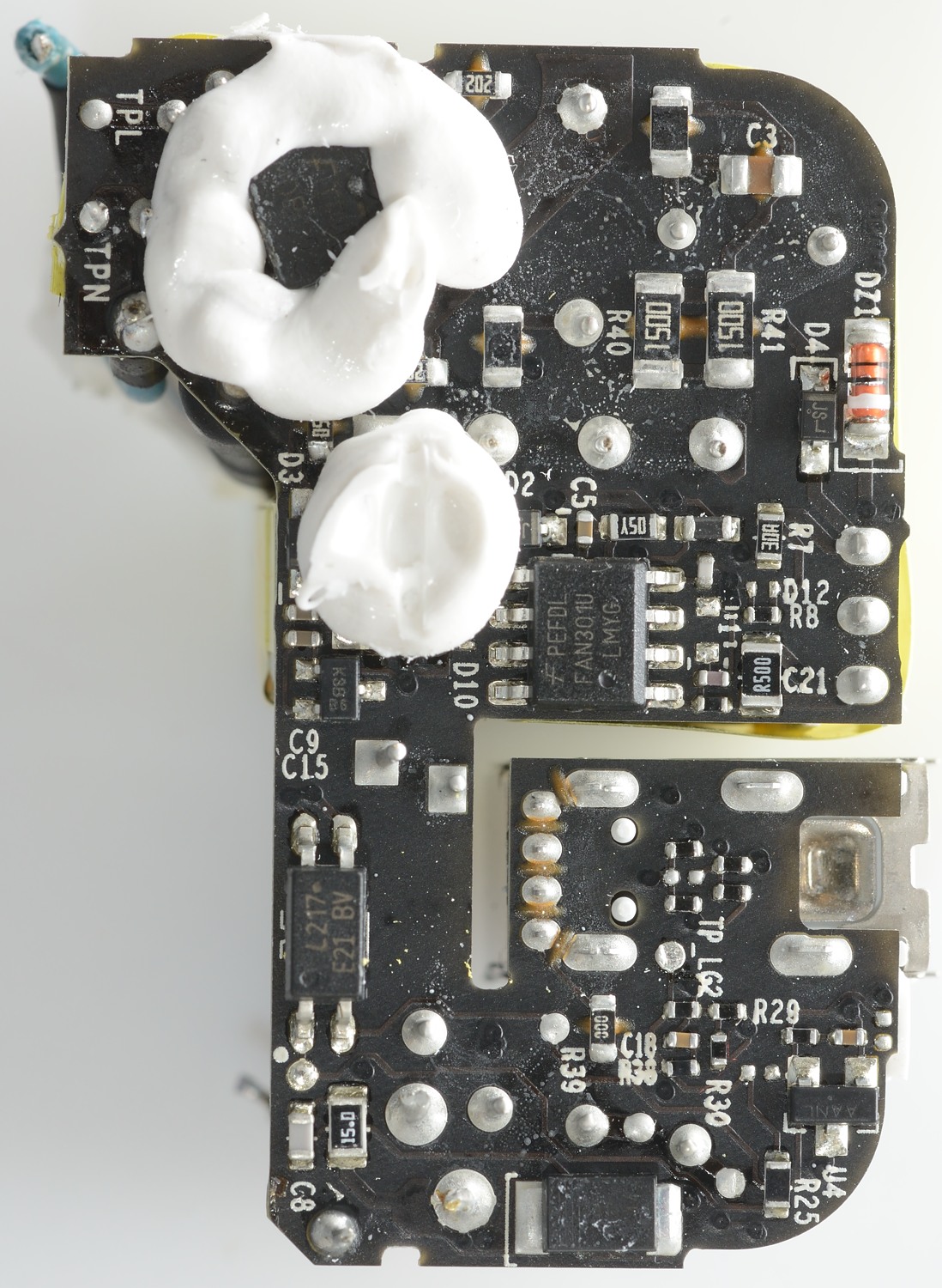
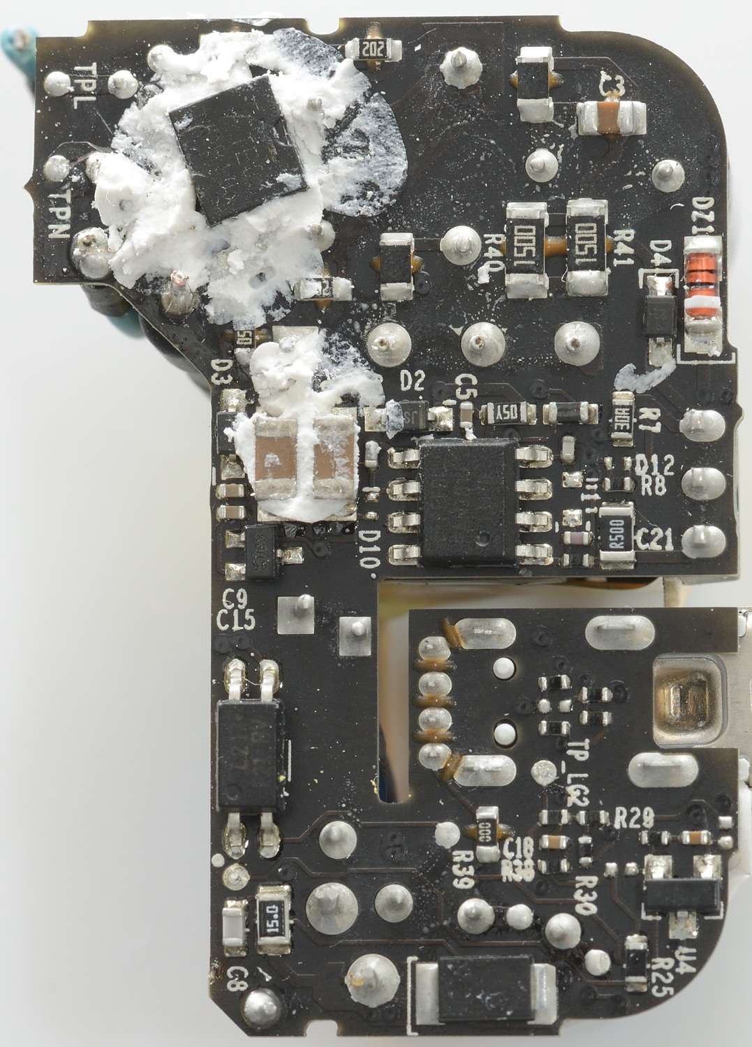
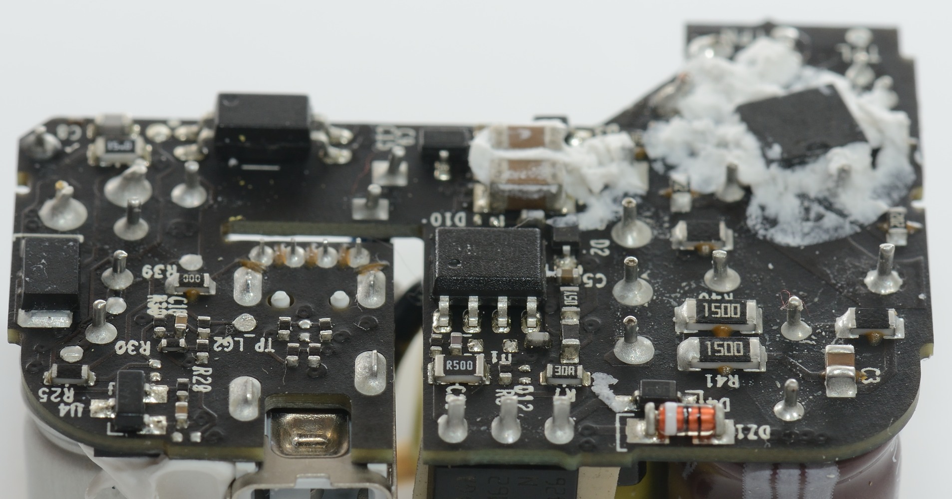
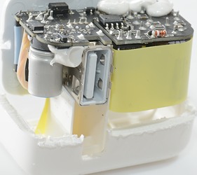
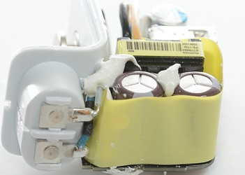
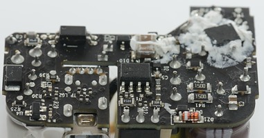
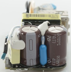
The circuit board have some white stuff on it, probably to improve isolation, it hides a bridge rectifier and two capacitors.
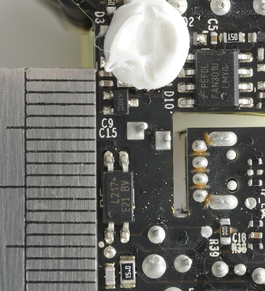
A switch mode controller IC and a opto feedback chip can also be seen on the circuit board.
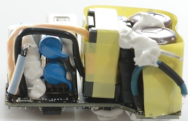

The two blue capacitors is the safety capacitors. There is also a fuse and it is directly connected to the power input.
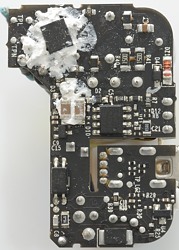
Without the isolation tape both inductors can be seen, both the common mode at the input and a series inductor.


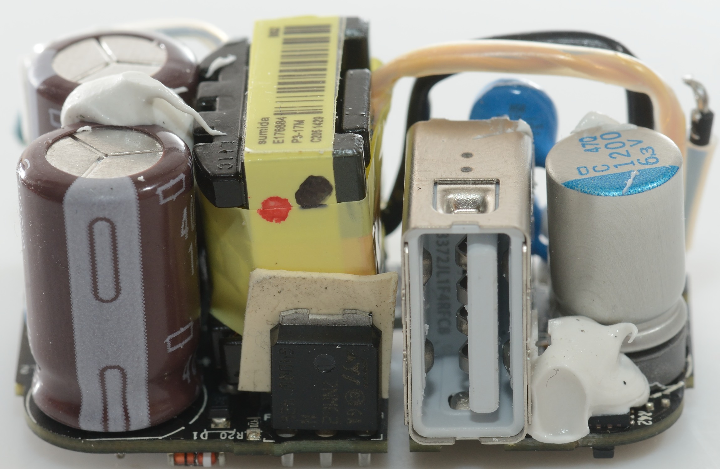
The output wires from the trafo goes around the isolation barrier and to the edge of the circuit board.
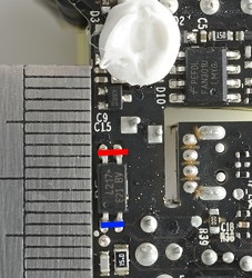
Below the capacitor is a chip. The plastic stand below the capacitor must be something special made for Apple with a hole for the chip.
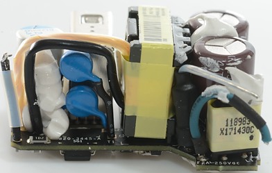
The rectifier diode is on the other side of the circuit board.
Without the tape the power transistor can also be seen
It is probably the opto feedback that limits the isolation distance.
Testing with 2500 volt and 5000 volt between mains and low volt side, did not show any safety problems.
Conclusion
It is no surprise that this charger can deliver the rated current with fairly low noise and is safe. I am impressed with its efficiency at higher current, it is above 80%. The actual construction looks on the expensive side, but it makes the charger very compact.
It is a very good charger, but mostly for Apple equipment due to the coding.
Notes
Index of all tested USB power supplies/chargers
Read more about how I test USB power supplies/charger
Another tear down and much more technical analysis of an iPad charger (older generation) by Ken Shirriff