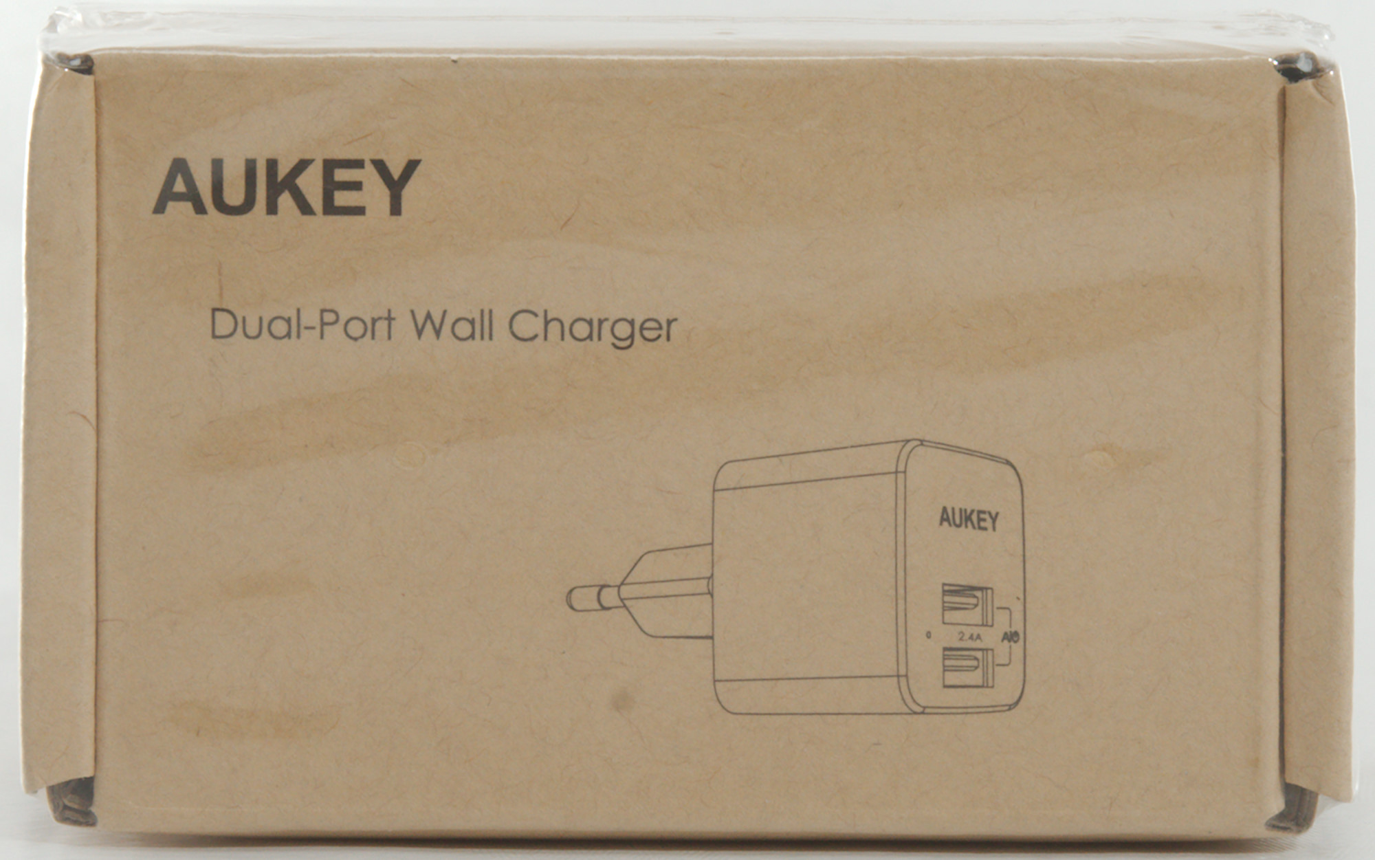
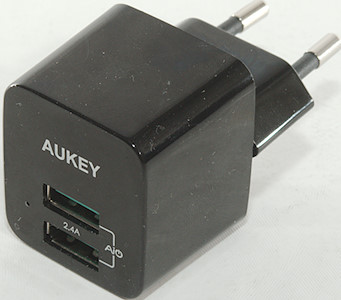
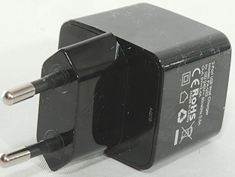
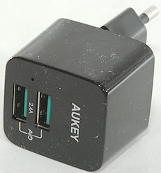
Aukey Dual Port Wall Charger PA-U32
Official specifications:
- Brand Name: AUKEY
- USB Ports: 2
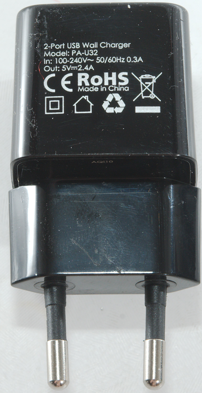
- Output: 5V/2.4A
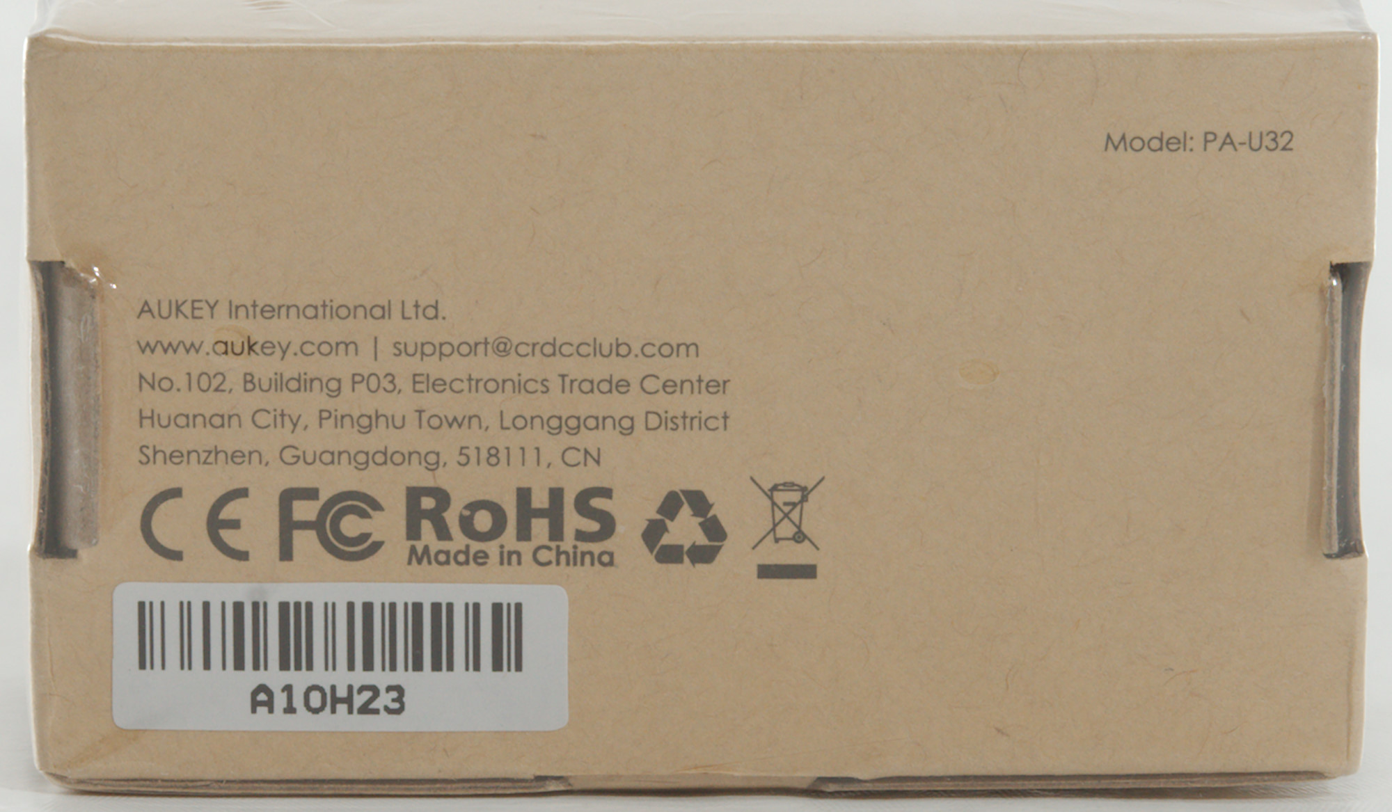
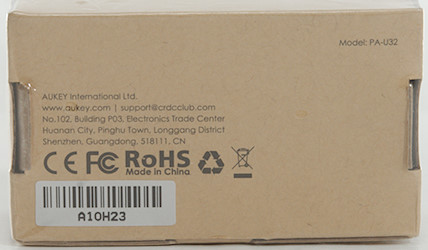
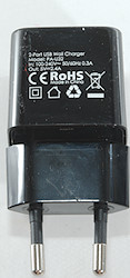
- Quality Certification: RoHS,CE,FCC
- Output Interface: USB
- Type: Travel
- Model Number: PA-U32 2 Port tiny USB charger
- Support Quick Charge Technology: No
- Input: 100-240V/0.15A
- Power Source: A.C. Source
- Charger: USB Charger,USB Adapter,Phone Charger
I got it from a Aliexpress dealer: aukey official store

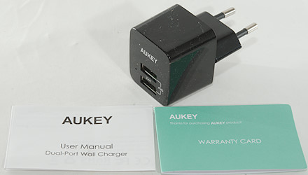
The box included the charger, a instruction sheet and a warranty card.
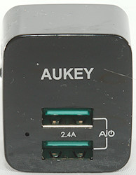
There is a small hole in the front with a weak white led behind it.
Measurements
- Power consumption when idle is 0.07 watt
- USB outputs is auto coding with DCP, Samsung, Apple 2.4A and QC2 5V
- Both outputs are in parallel.
- Weight: 42.6g
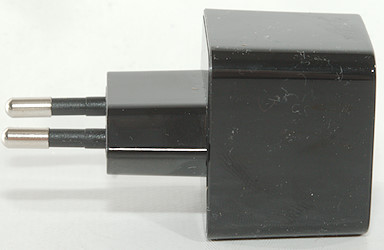
- Size: 68 x 37.6 x 35.3mm
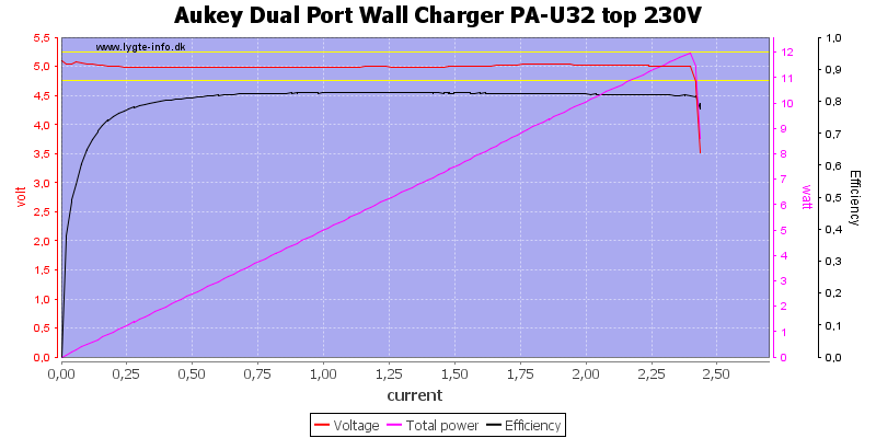
The top output can deliver about 2.4A
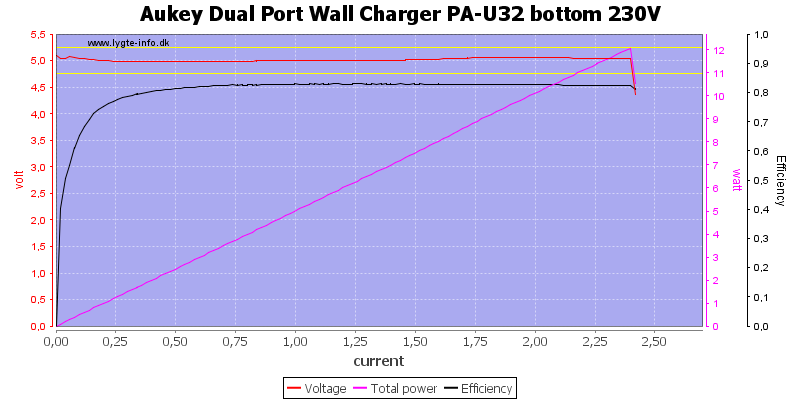
It is the same for the bottom output.
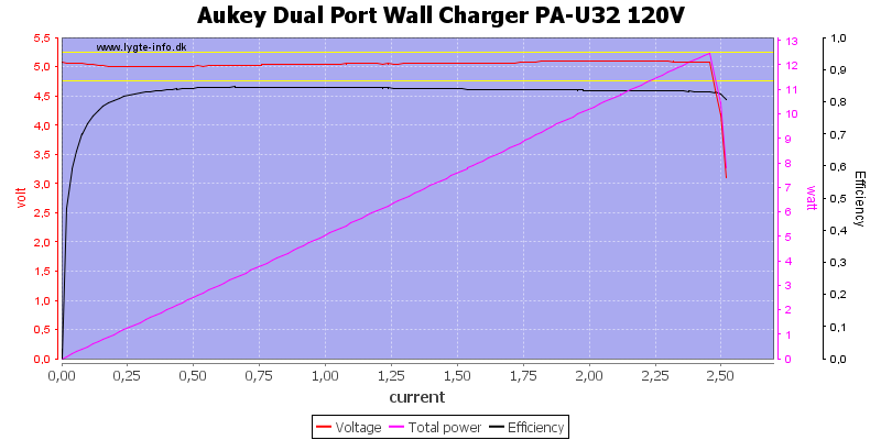
And also when used in parallel at 120VAC, the limit is slightly higher at 120VAC.
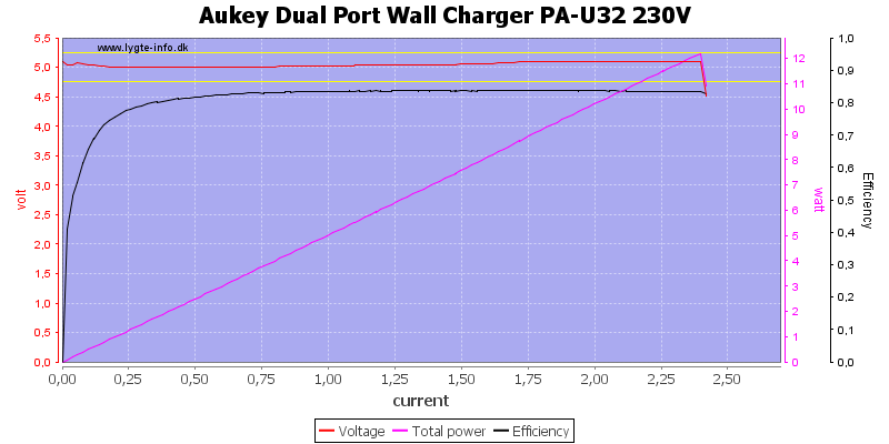
Or at 230VAC.
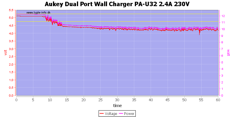
The limit is too close to 2.4A, the charger cannot deliver 2.4A for more than 10 minutes, before output drops.
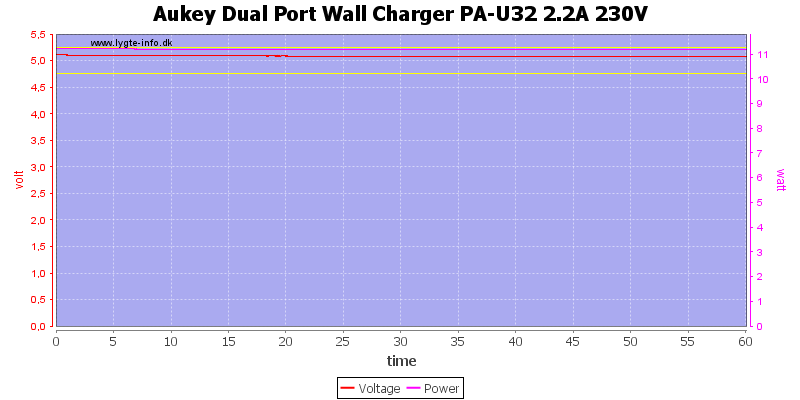
Reducing the output to 2.2A helps, now the charger can deliver current for one hour.
The temperature photos below are taken between 30 minutes and 60 minutes into the one hour test.
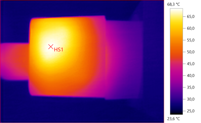
HS1: 68.3°C
HS1 is the transformer
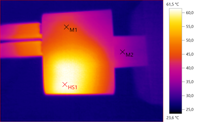
M1: 44.5°C, M2: 35.8°C, HS1: 61.5°C
HS1 is the transformer
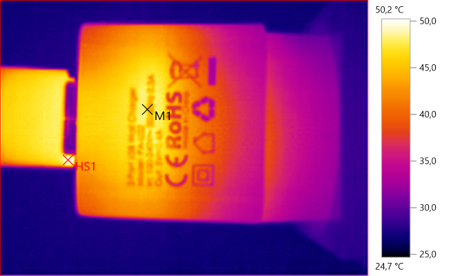
M1: 45.8°C, HS1: 50.2°C
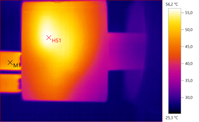
M1: 47.9°C, HS1: 56.2°C
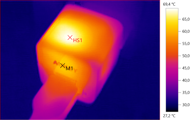
HS1: 69.4°C, M1: 57.8°C
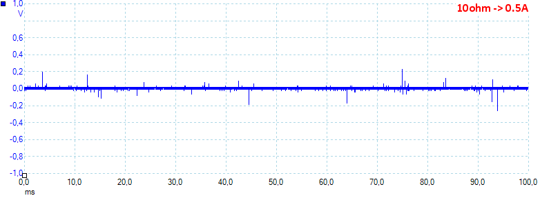
Noise at 0.5A load is: 17mV rms and 803mVpp.
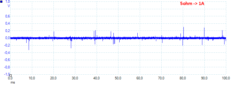
Noise at 1A load is: 21mV rms and 715mVpp.
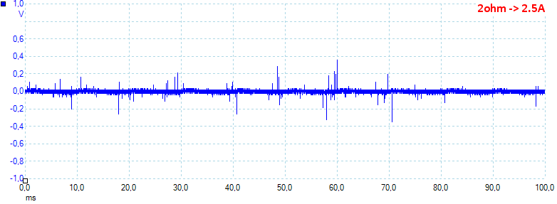
Noise at 2.5A load is: 67mV rms and 949mVpp.
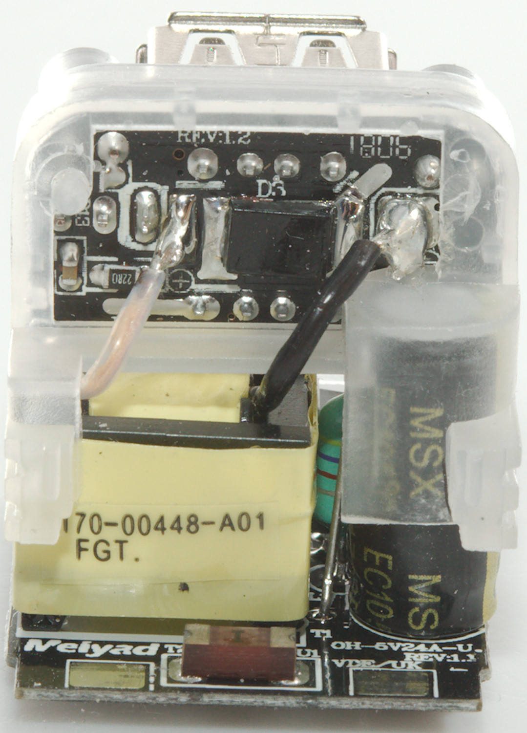
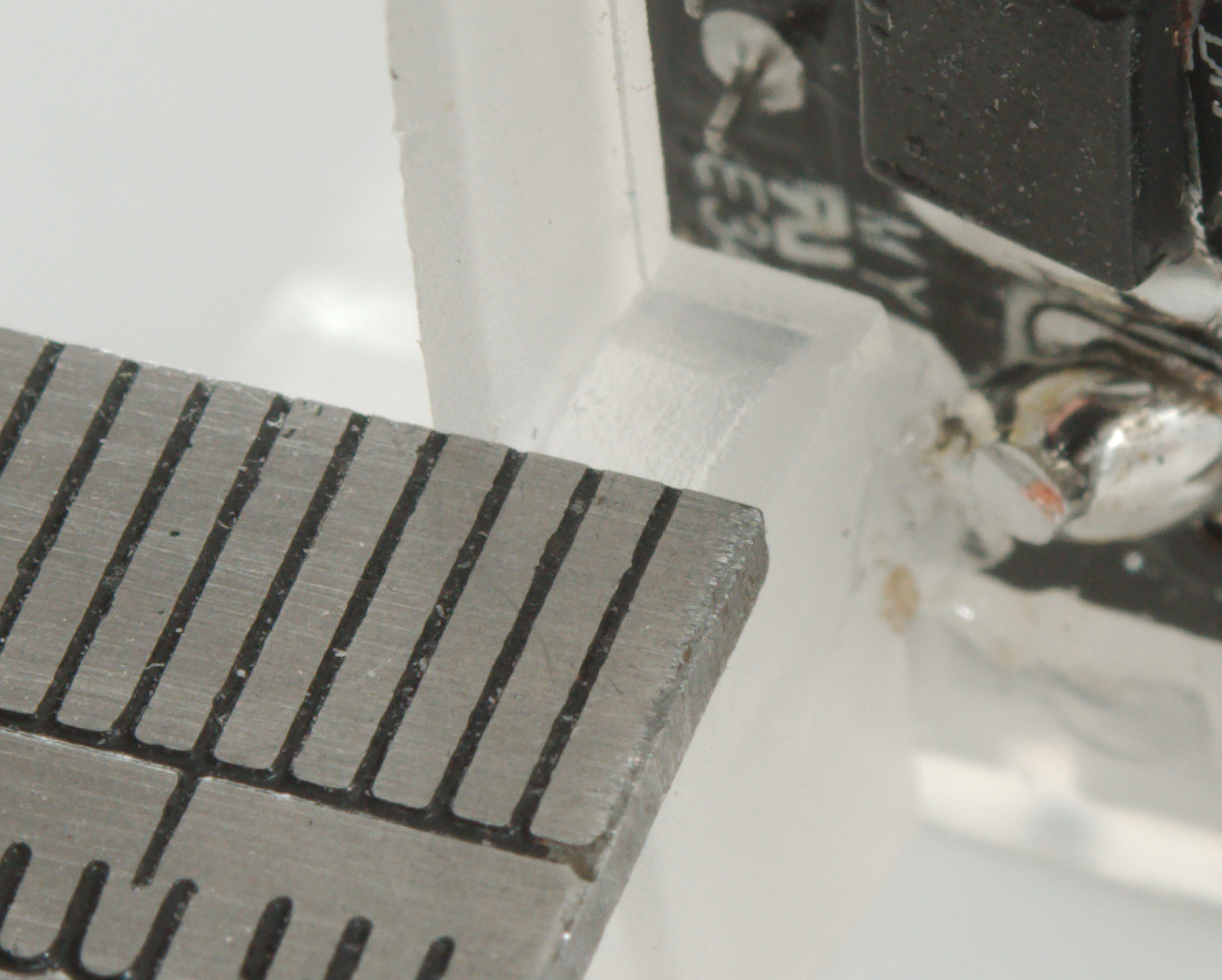
Tear down
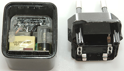
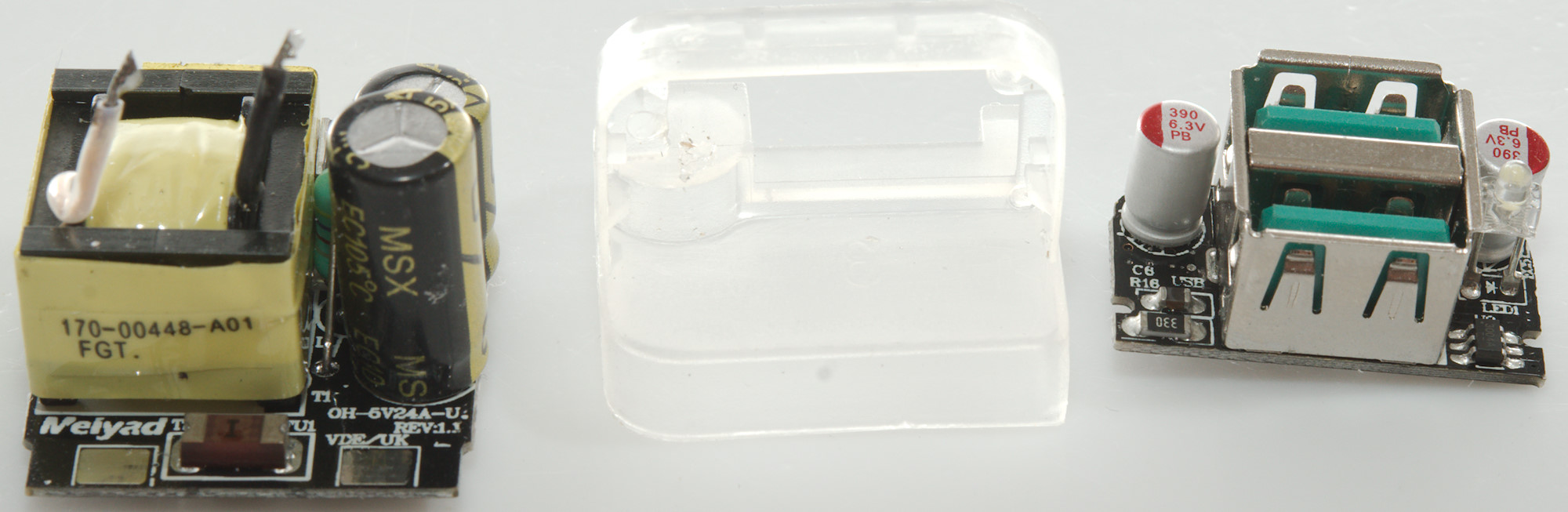
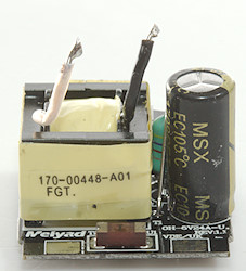
My vice could break the glue and the I could pull it apart. The electronic is in a clear plastic holder.
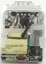
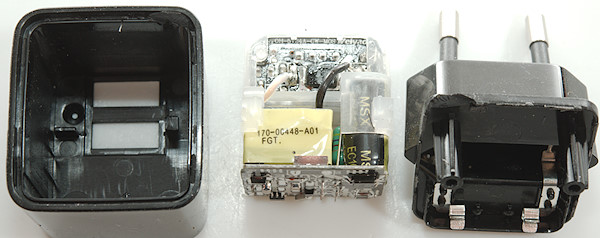
A few more views of the plastic holder. The electronic is on two circuit boards, one for mains and one for low voltage, due to the plastic holder there is very good isolation between them.
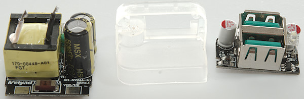
The two circuit board and the holder.
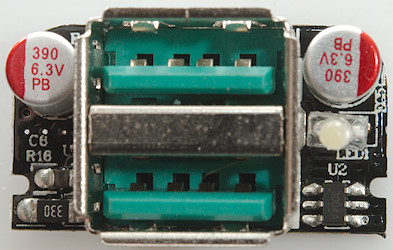
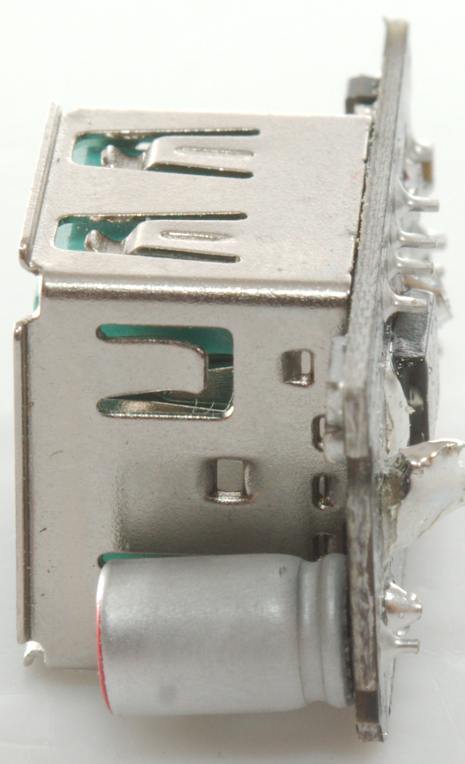
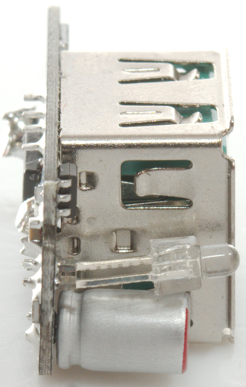
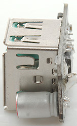
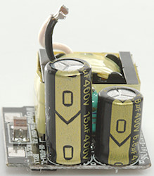
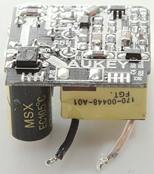
One this side is the led and the auto coding chip (U2: CW3004)
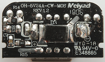
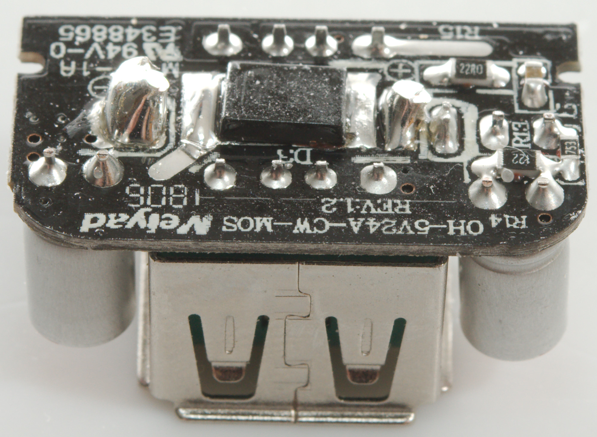
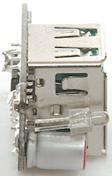
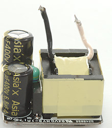
On this side is the rectifying diode.
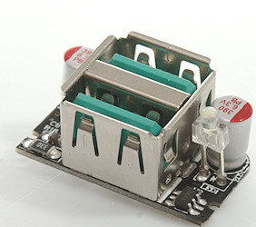
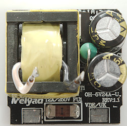
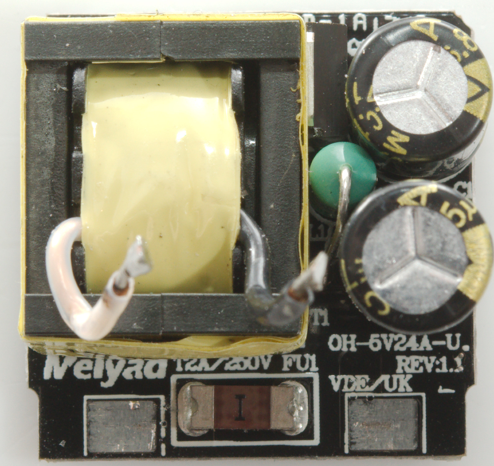
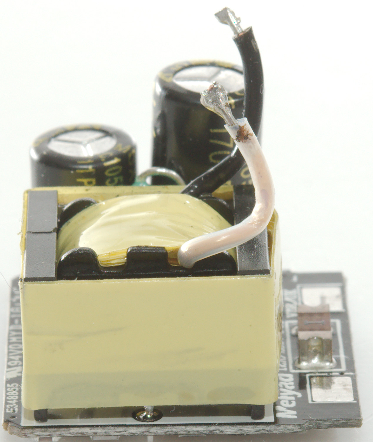
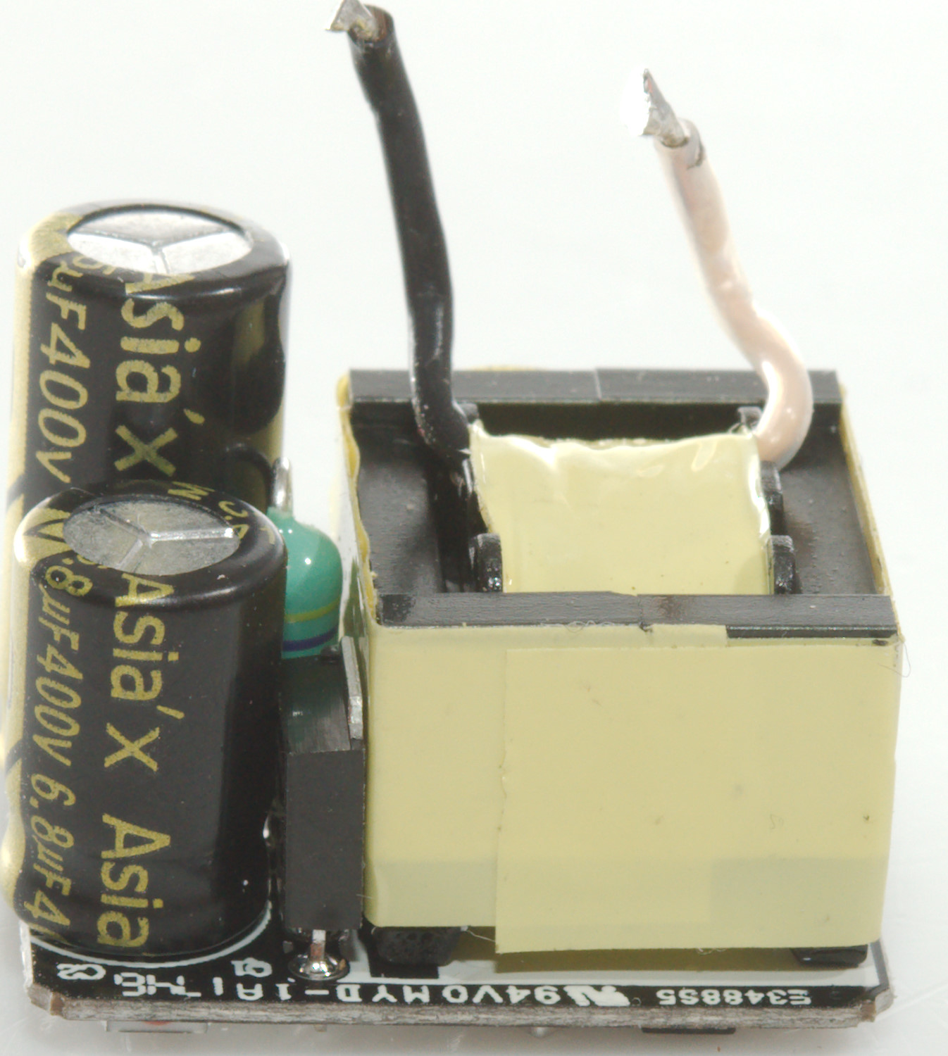
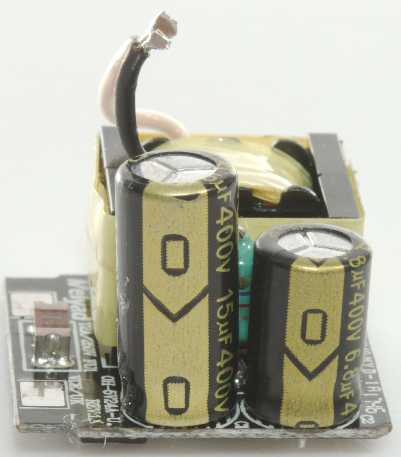
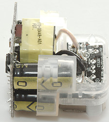
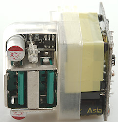
This is the mains circuit board with the fuse (FU1) and a inductor (L1) between the two smooting capacitors. There is also a switcher transistor (Q1) between one of the capacitors and the transformer.
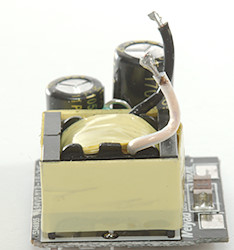
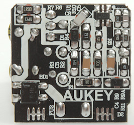
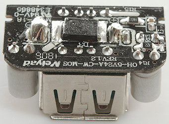
This side has a bridge rectifier (BD1) and a switcher controller (U1).
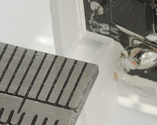
This small charger has very good safety distances due to the two circuit board with plastic between.
Testing with 2830 volt and 4242 volt between mains and low volt side, did not show any safety problems.
Conclusion
A very small charger with good safety and auto coding, but the total current output is a bit low for a dual output device
Notes
Index of all tested USB power supplies/chargers
Read more about how I test USB power supplies/charger
How does a usb charger work?