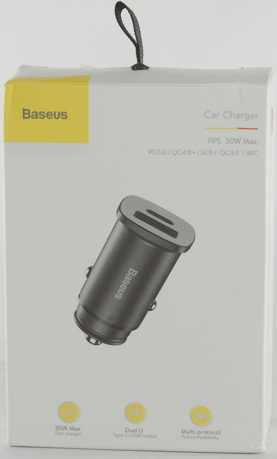
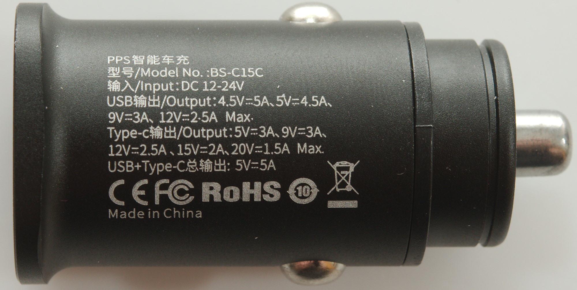
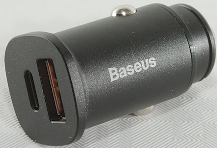
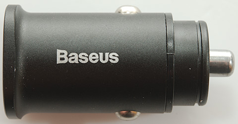
Baseus Car Charger QC PD 30W BS-C15C
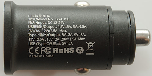
Official specifications:
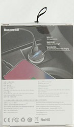
- 30W Output from USB-C Port, supporting PD3.0 PPS and QC4.0 protocols, backward compatible with Smasung AFC, Huawei SCP, OPPO quick charge, OnePlus Dash etc.
- Multiple Safety protection: over-charge, over current, over voltage, over power, short circuit, over-discharge and temperature protection
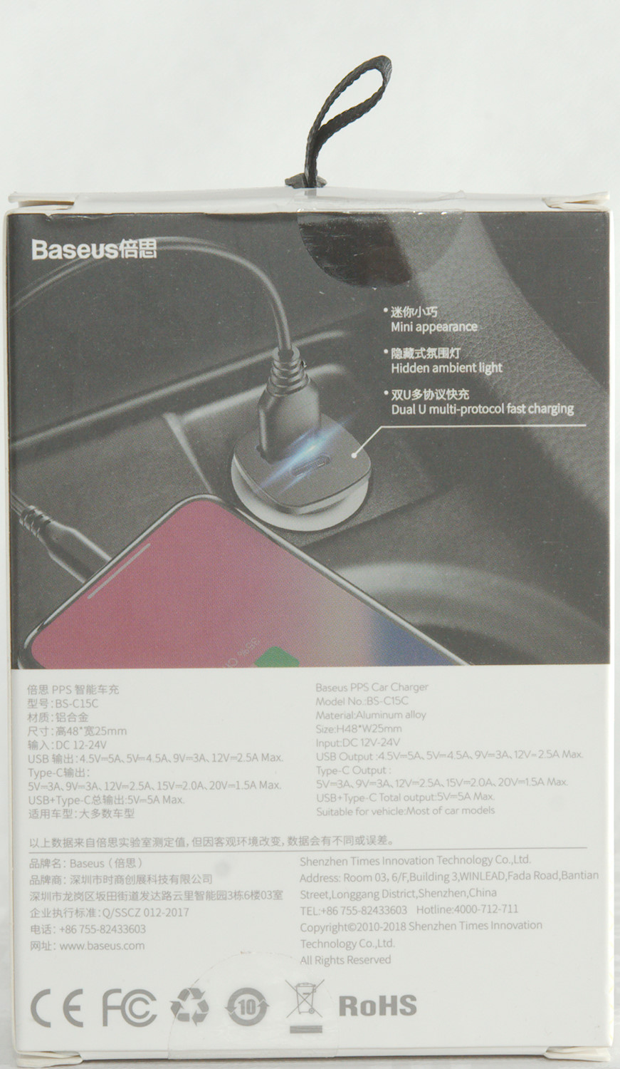
- When charging 2 devices at the same time, the output voltage will reduce to 5V on both ports, with total output max out at 5V5A.
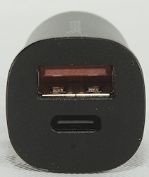
- Output USB-C (max 30W): 5V/3A, 9V3A, 12V2.5A, 15V2A (24V DC input), 20V1.5A(24V DC input)
- Output USB-A (max 30W): 4.5V/5A, 5V/4.5A, 9V/3A, 12V/2.5A.
I got it from Amazon.com.au
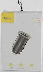
I got the charger in a cardboard box.
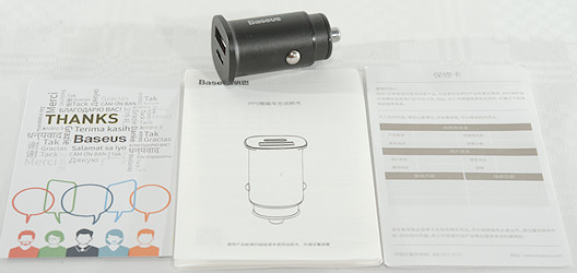
The box included the charger, warranty chart and a manual.
Measurements
- Power consumption when idle is 4mA from 12V and 24V
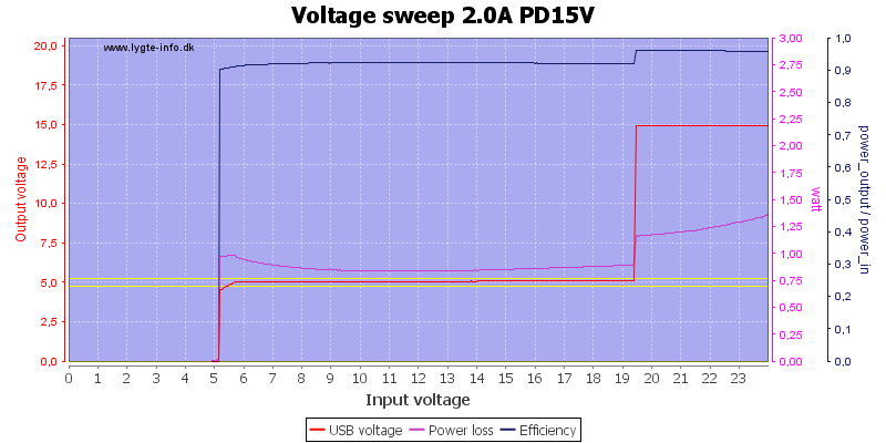
- PD output has 5V 2A, 9V 3A, 12V 2.5A, 15V 2A, 20V 1.5A, PPS:3-5V 3A, PPS:3-11V 3A
- 12V is disabled when voltage drops below 10.9V and is enabled when voltage is above 11.4V
- 15V is disabled when voltage drops below 13.3V and is enabled when voltage is above 14.8V
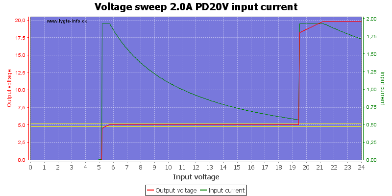
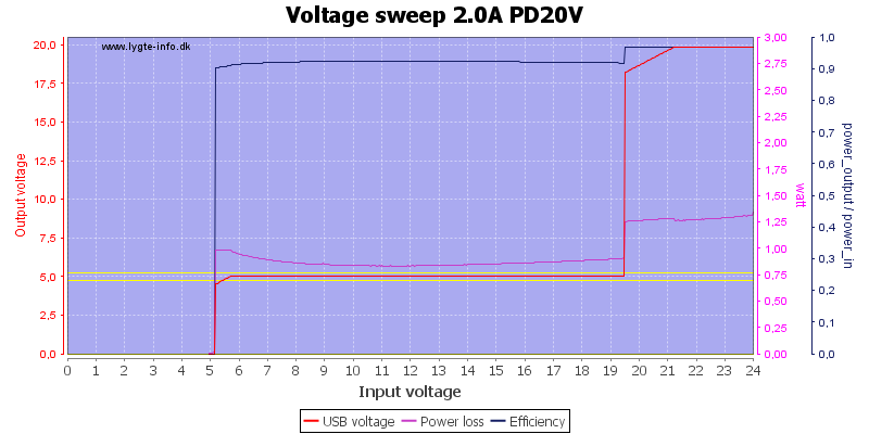
- 20V is disabled when voltage drops below 19.2V and is enabled when voltage is above 20.7V
- PD output is coded as Apple 2.4A, DCP, Samsung, QC2 5V
- USB output is auto coding with Apple 2.4A, Samsung, DCP, QC3, Samsung-AFC, Huawei-FCP, Huawei-SCP
- Minimum QC3 voltage is 3.7V
- Generally only one output will work at a time, but when using a resistor based USB-C coding and a standard USB device (No QC) it is possible to use both outputs.
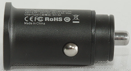
- Both outputs can be turned on/off from the charger.
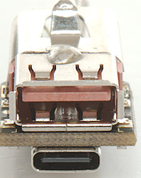
- The charger has a blue led that is visible in the QC connector.
- Weight: 19.2g
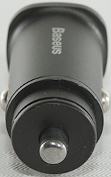
- Length: 46mm
- Largest diameter: 26mm
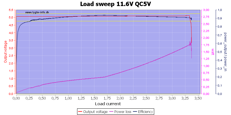
The overload protection is at around 3.2A at 5V output.
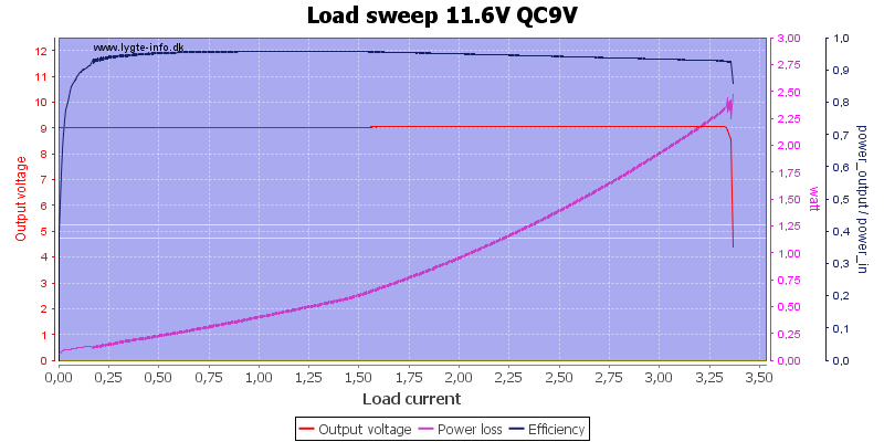
THe same at 9V
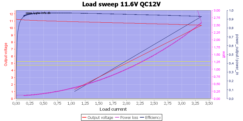
And at 12V
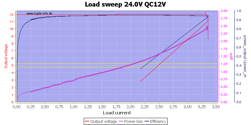
And the same with 24V input.

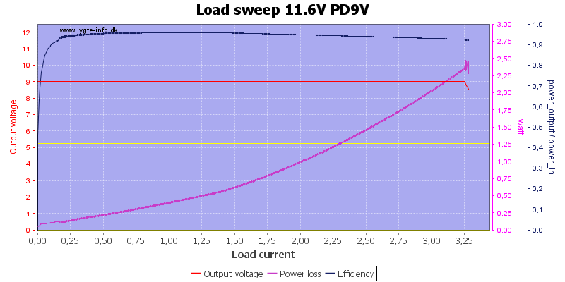
The PD output has the same limit.

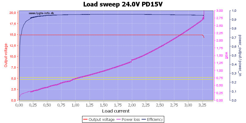
Up to 15V
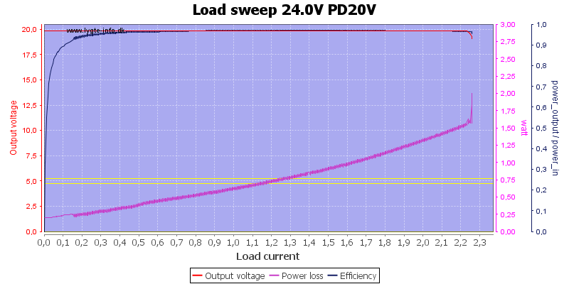
But at 20V the output maximum current is limited to 2.2A (It is more than rated).
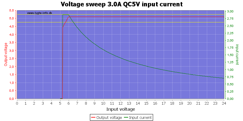
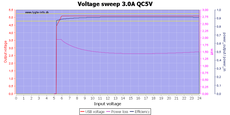
The 5V output works down to 6V input
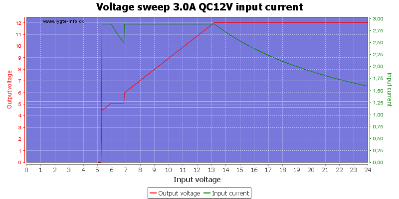
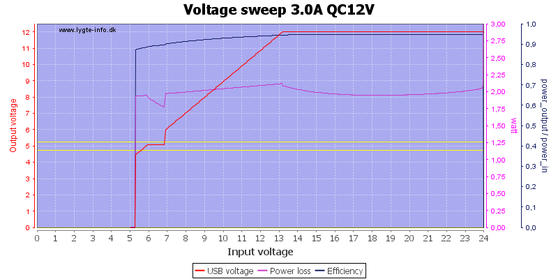
12V output need 13V input or it will be low.
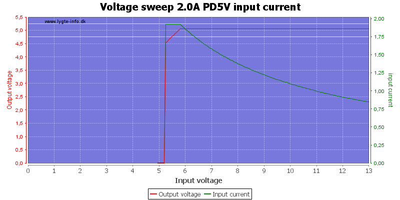
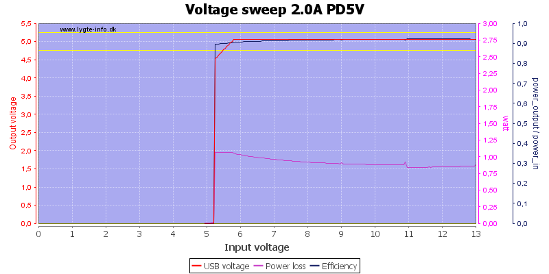
The PD output also needs about 6V to deliver 5V output.
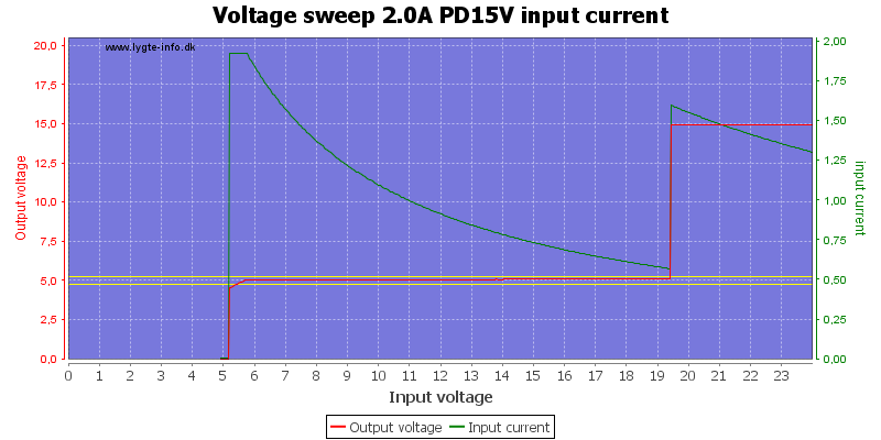
15V output will reset when voltage drops below the 20V limit, but it is possible to activate it again (My test equipment do not do that).
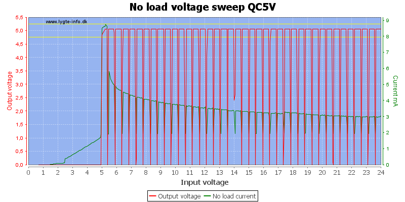
The electronic is testing the output for a load when nothing is connected.
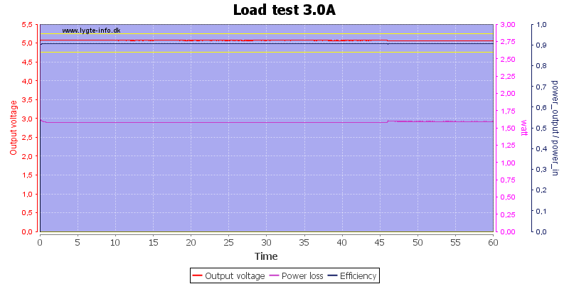
I did this test at 3A on the QC output.
The temperature photos below are taken between 30 minutes and 60 minutes into the one hour test.
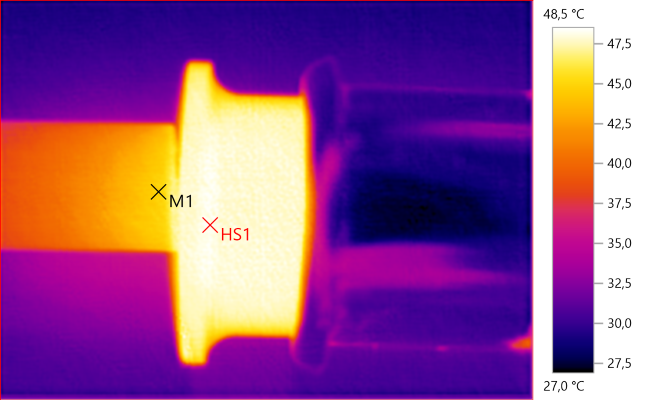
M1: 44.9°C, HS1: 48.5°C
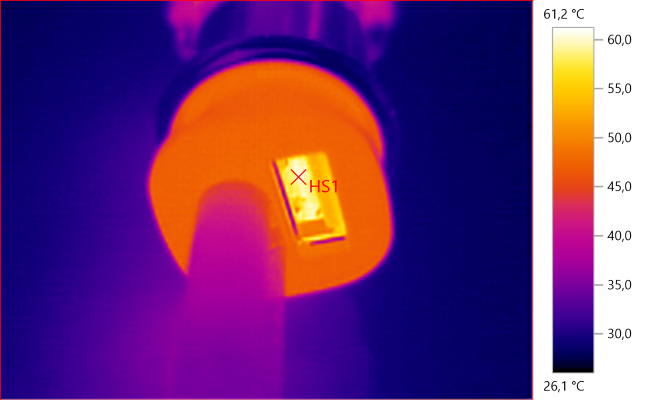
HS1: 61.2°C
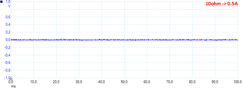
Noise at 0.5A output is 4mV rms and 65mVpp
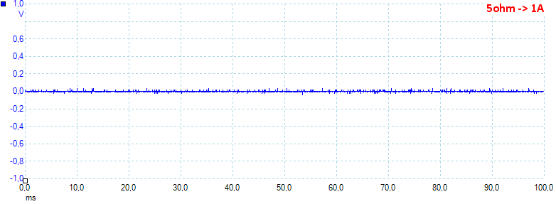
Noise at 1A output is 8mV rms and 149mVpp
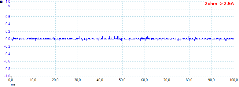
Noise at 2.5A output is 6mV rms and 125mVpp
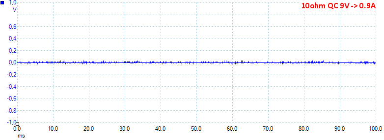
Noise at 0.9A output is 4mV rms and 80mVpp
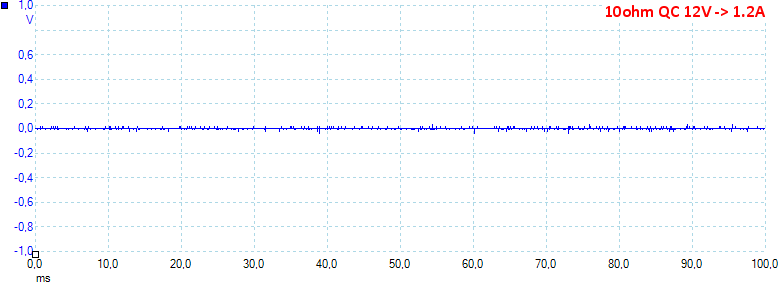
Noise at 1.2A output is 4mV rms and 84mVpp
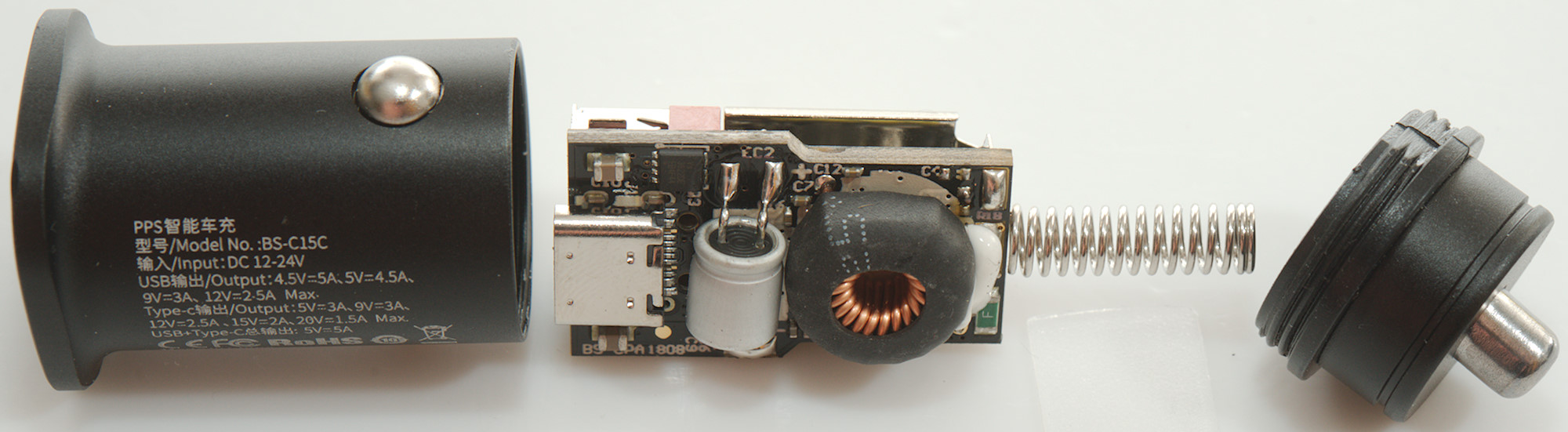
Tear down
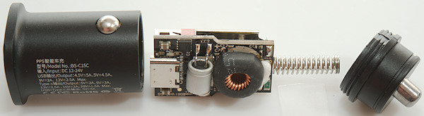
I could screw the bottom off and then pull the circuit out.
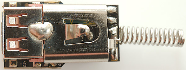
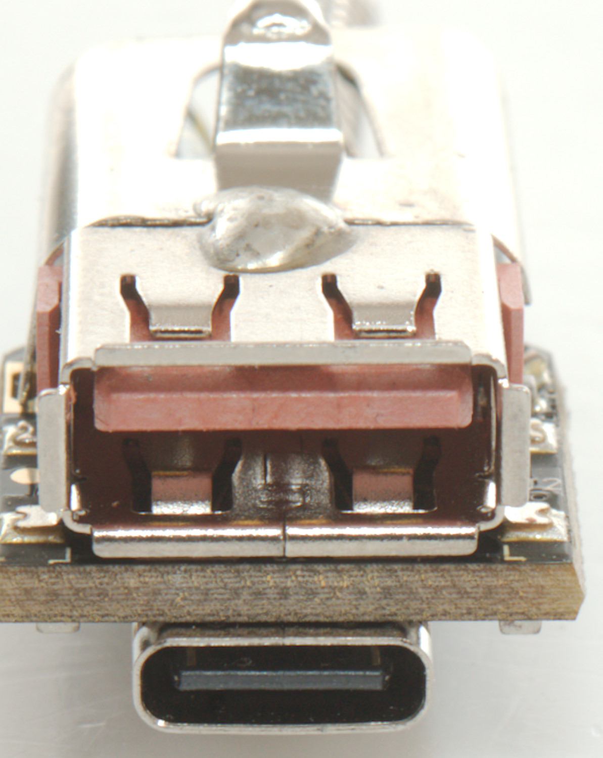
The electronic is hidden behind this shield.

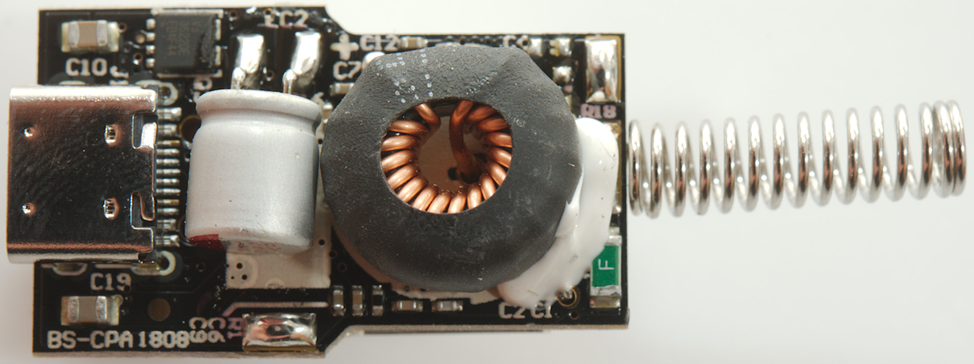
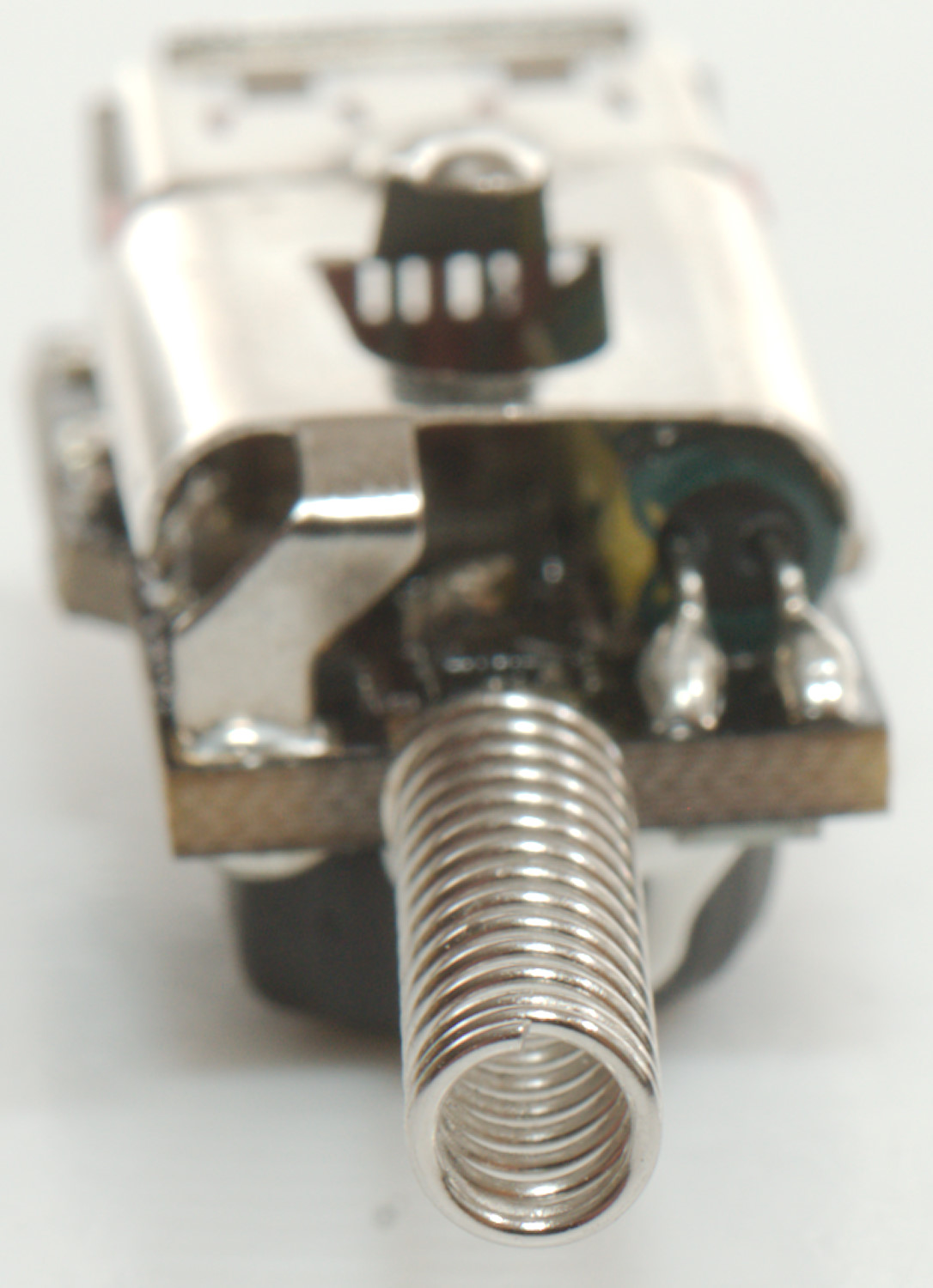
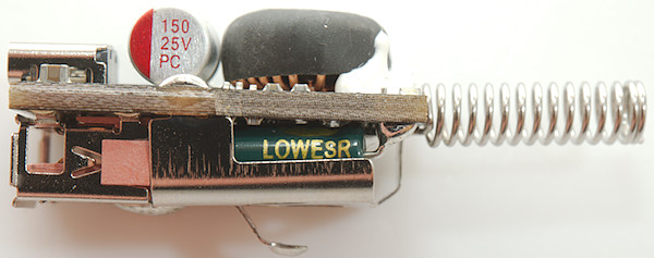
Here is the input fuse, the inductor and the dual output transistor to turn each output on separately.


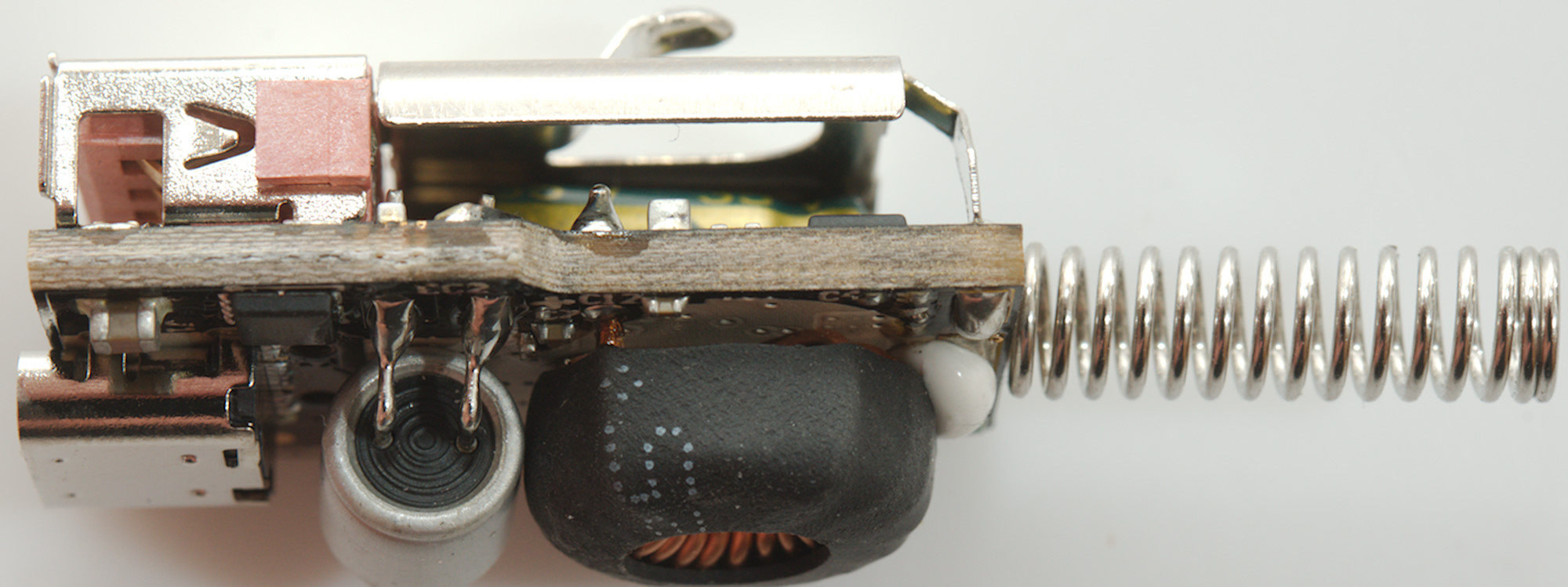
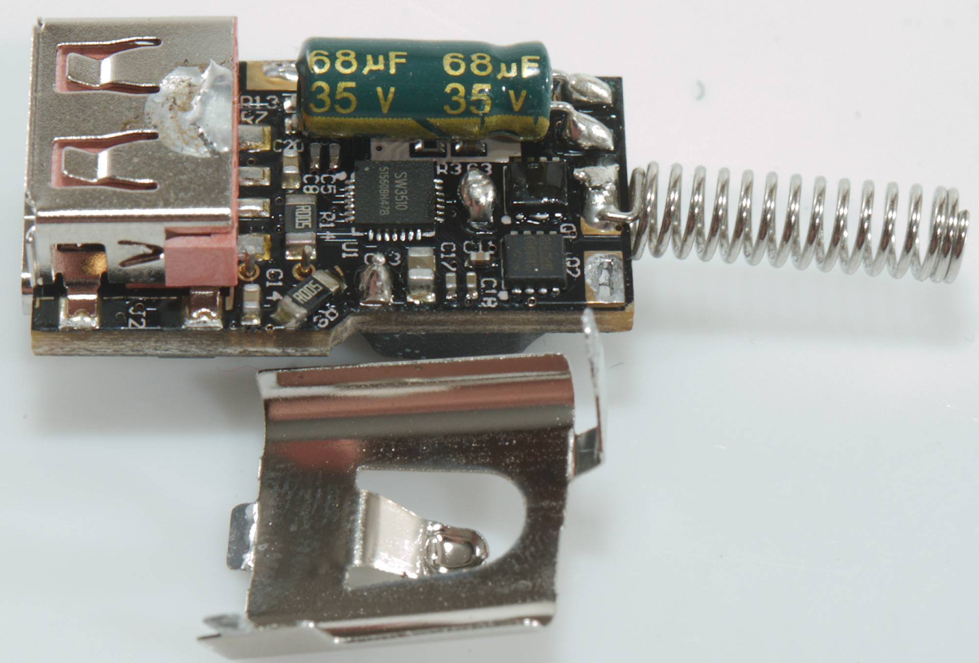
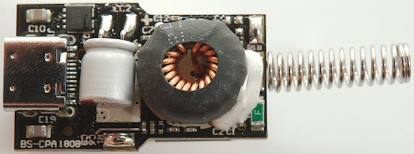
Some soldering and I could get the shield off.
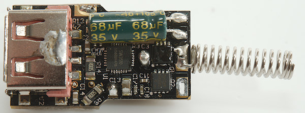
Below it is the switcher and dual charge controller (U1: Marked SW3510) and two switcher transistors (Q1 && Q2). Each output has it own sense resistor (R9 & R14: 2 x 0.005ohm).
Conclusion
This charger is mostly for one device at a time, not for two. It only has one converter, this means when using PD or QC it will often disable the opposite output. The automatic output switch did also turn on/off a couple of extra times.
The output power is fine for a single device and the charger supports just about everything, it also has low noise and good overload protection.
Notes
I got this charger from reader "Mostly Melbourne"
Read more about how I test USB power supplies/charger
Compare car chargers and other DC supplied chargers