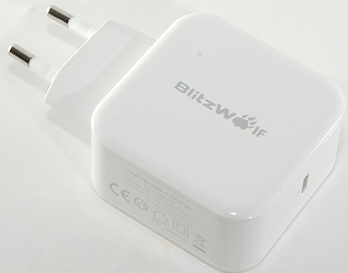
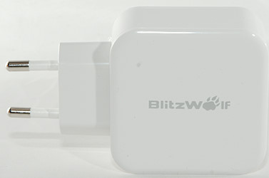
BlitzWolf 30W PD usb charger BW-S10
Official specifications:
- Brand: BlitzWolf
- Model: BW-S10
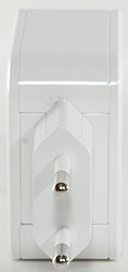
- Plug: EU
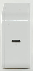
- USB Port: USB Type-C Port
- Total Power: 30W (Max)
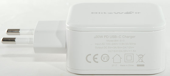
- Input: AC 100-240V~50/60Hz 0.8A
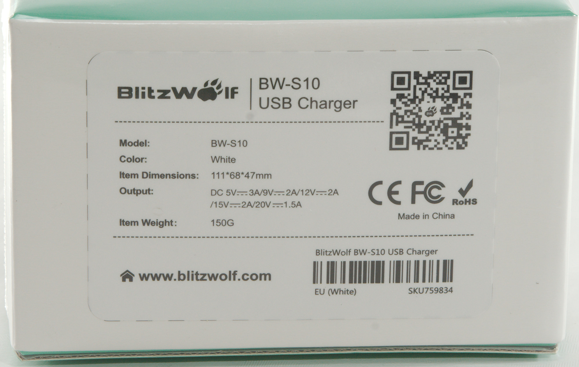
- Output: PD Mode: 5V/3A, 9V/2A, 12V/2A, 15V/2A, 20V/1.5A
- Output: QC3.0 Mode: 5V/3A, 9V/2A, 12V/1.5A
- Size: 54.5*54*28.5mm/2.15*2.14*1.12inch
- Weight: 150g±10g
- Fast Charging: USB PD (Power Delivery ), QC2.0, QC3.0, BC1.2
I got it from Banggood
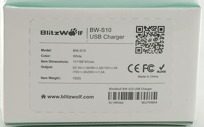
Blitzwolf uses a white cardboard box with some specifications on it.
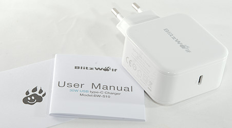
The box contained the charger, manual and a note.
Measurements
- Power consumption when idle is 0.07 watt at 230VAC
- PD modes: 5V 3A, 9V 3A, 12V 2.5A, 15V 2A, 20V 1.5A
- In addition to PD output also supports QC3 up to 12V and DCP, but only if there is a resistor to turn USB-C on.
- Default state for usb output is off.
- Lowest QC3 voltage is 3.5V
- Size: 92 x 54.2 x 28.3mm
- Weight: 93g
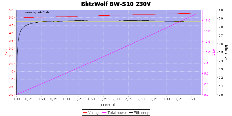
Output is rated for 3A at 5V and can deliver a bit above 3.5A, this is fine. The output voltage increases with load, this charger has cable compensation.
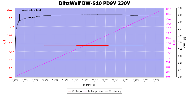
At 9V the output current is the same.
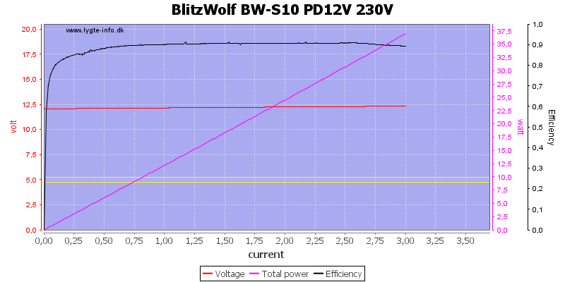
At 12V the current is limited to 3A
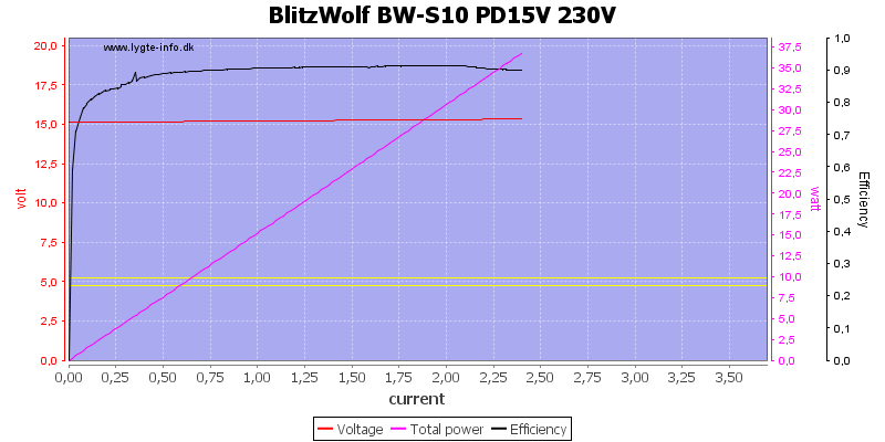
At 15V it is down to about 2.3A
Overloading will drop the port to 5V after a short off period.
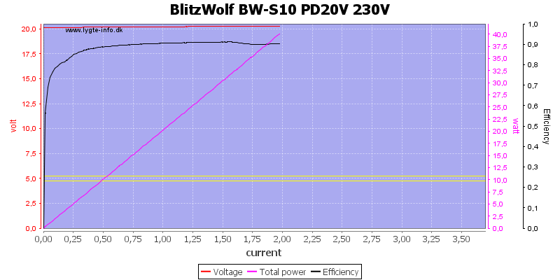
And at 20V it is 2A.

Also with 120VAC input.
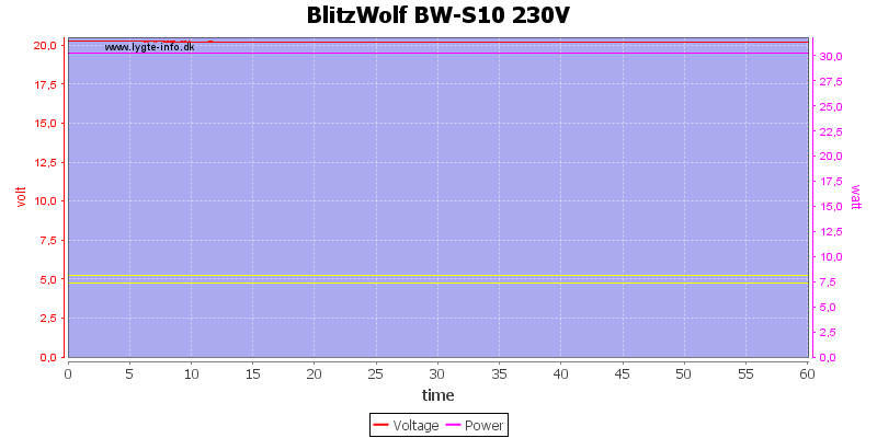
Running at 20V 1.5A for one hour is no problem.
The temperature photos below are taken between 30 minutes and 60 minutes into the one hour test.
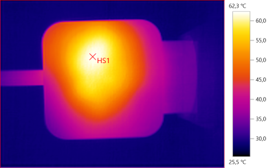
HS1: 62.3°C
HS1 is the transformer.
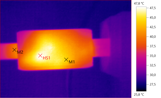
M1: 44.1°C, M2: 39.8°C, HS1: 47.8°C
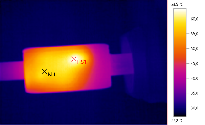
M1: 58.4°C, HS1: 63.5°C
HS1 is the white stuff between the transformer and the enclosure, it is transferring heat from the transformer.
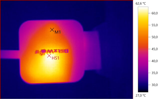
M1: 50.3°C, HS1: 62.6°C
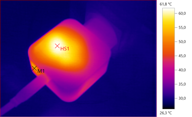
M1: 52.8°C, HS1: 61.8°C
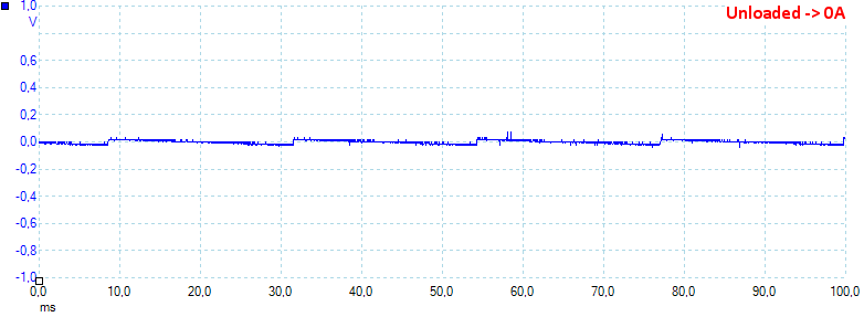
Unloaded the noise is 15mV rms and 134mVpp
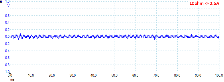
At 0.5A the noise is 25mV rms and 185mVpp
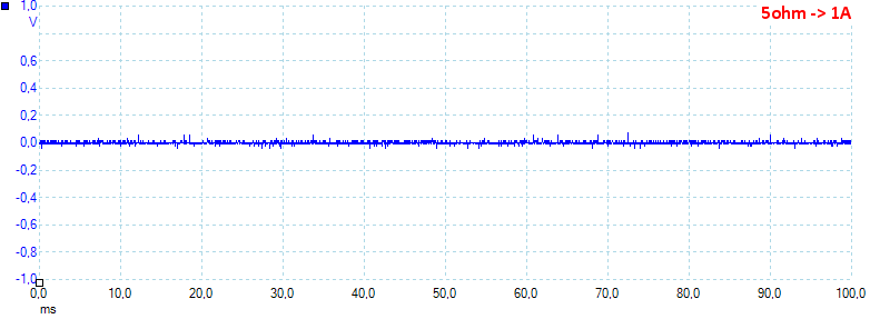
At 1A the noise is 8mV rms and 150mVpp
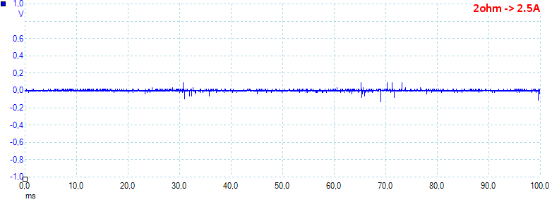
At 2.5A the noise is 16mV rms and 307mVpp
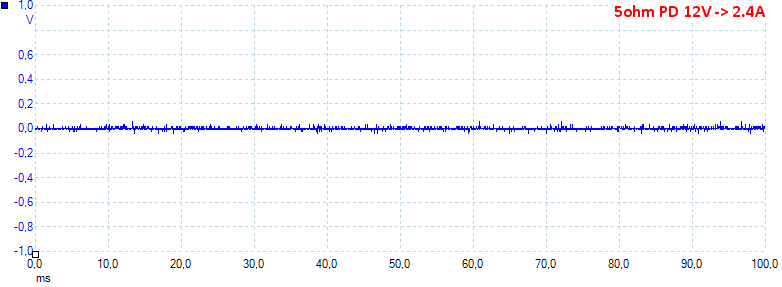
At PD 12V 2.4A the noise is 8mV rms and 152mVpp
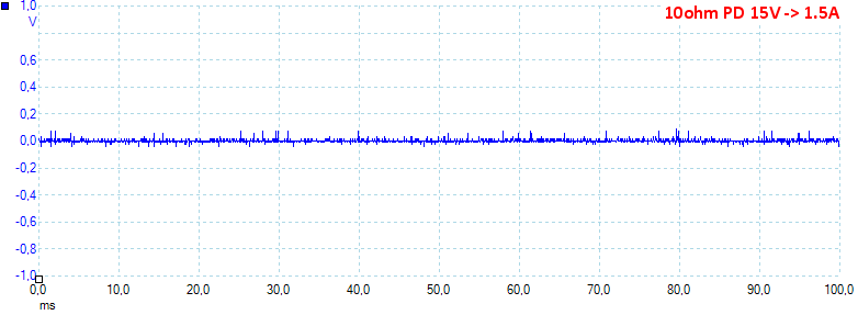
At PD 15V 1.5A the noise is 9mV rms and 181mVpp
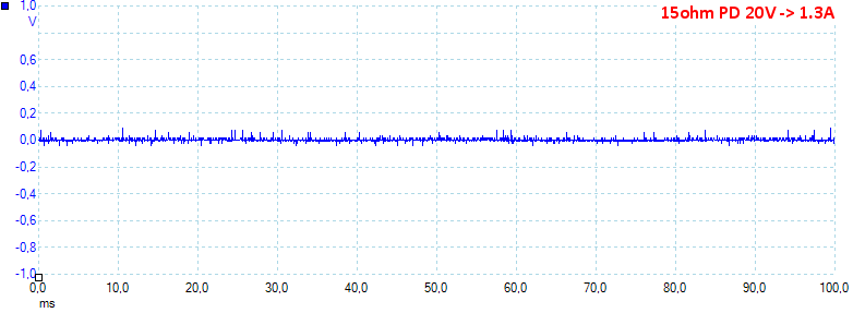
At PD 20V 1.3A the noise is 9mV rms and 163mVpp, all noise values are very low.
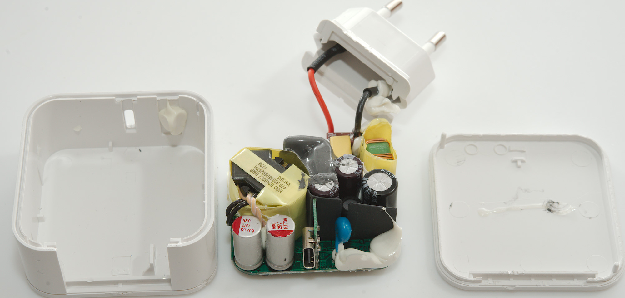
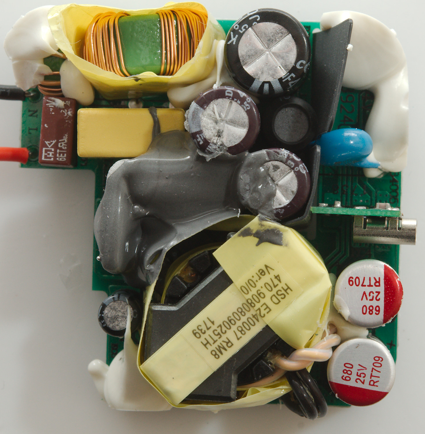
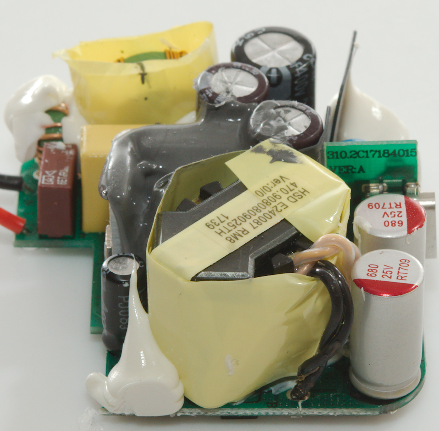
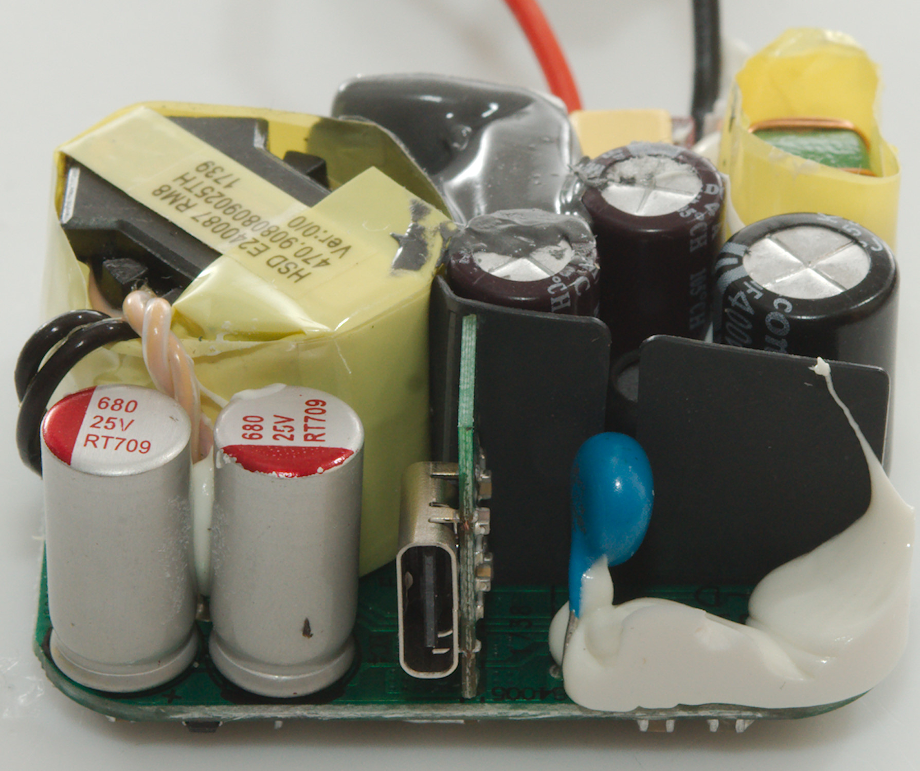
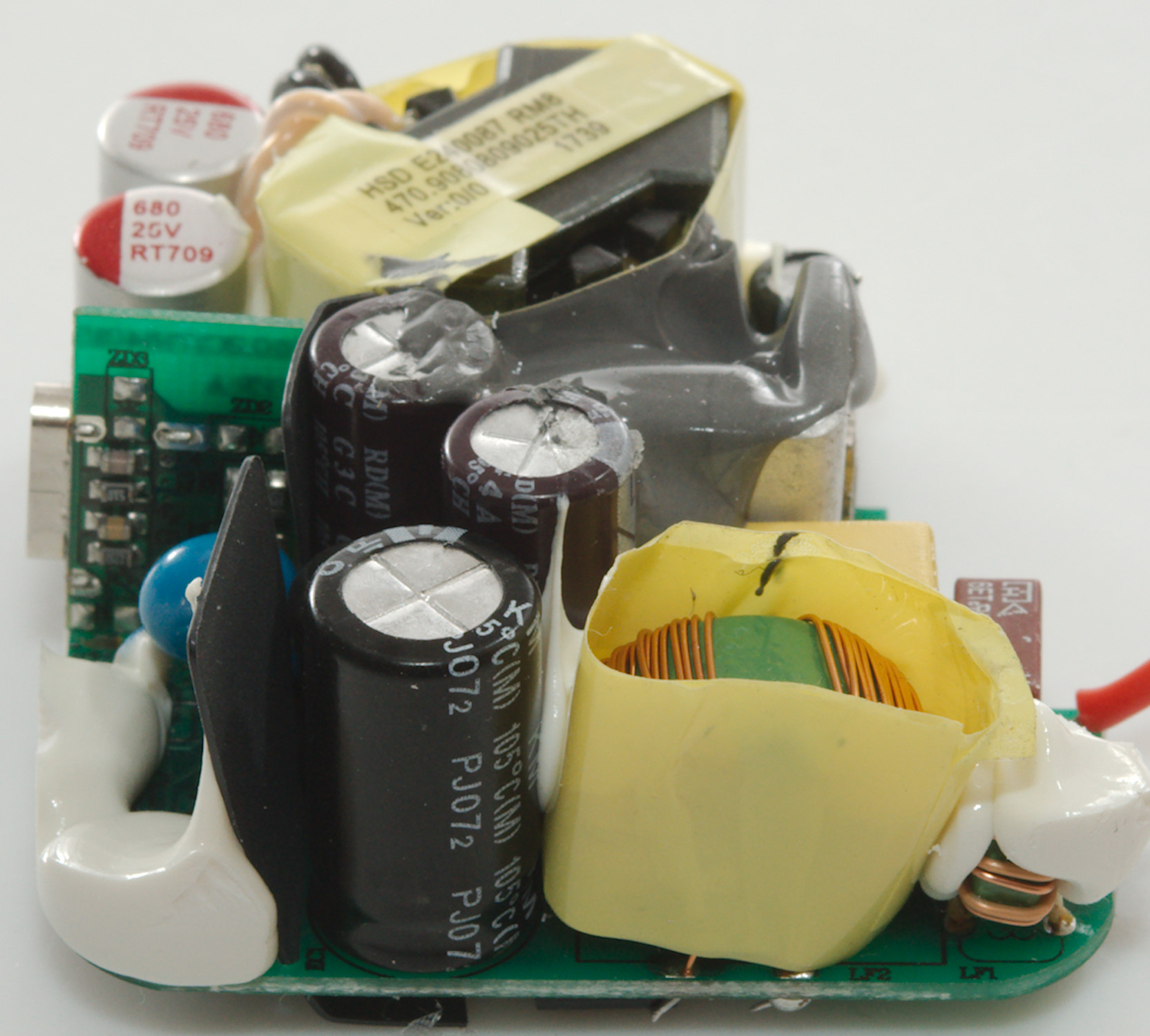
Tear down
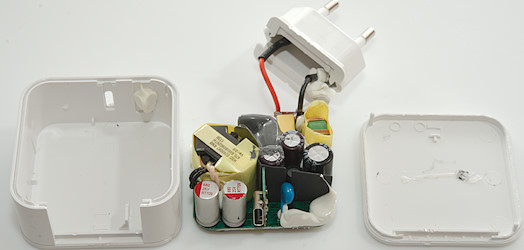
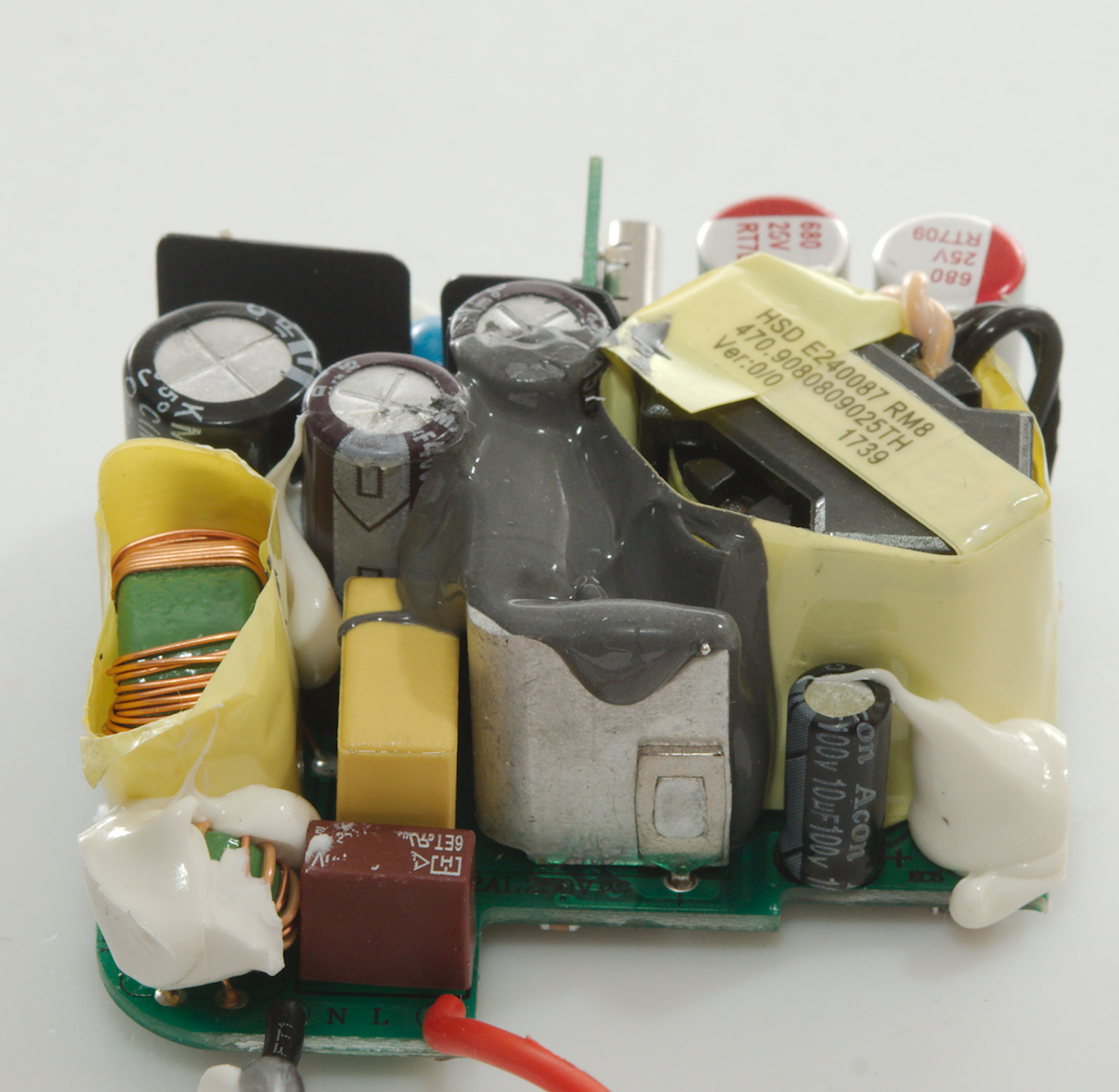
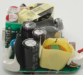
Some pressure with a vice and I could break the lid off.
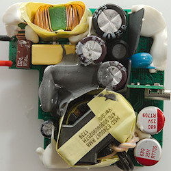
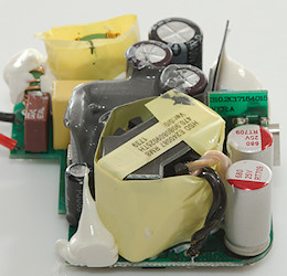
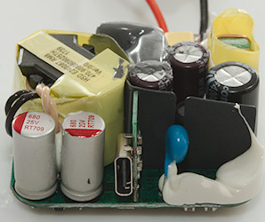
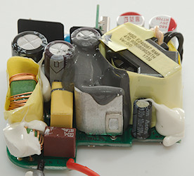
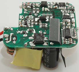
At the mains input is a fuse and two common mode coils. There is also an inductor between the smoothing capacitors. The safety capacitor is mounted through a slit in the isolation paper. The mains switcher transistor in on a heatsink inside the gray stuff (The pins can be seen on the other side of the circuit board). The usb-C connector is mounted on a small circuit board.
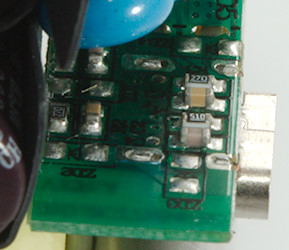
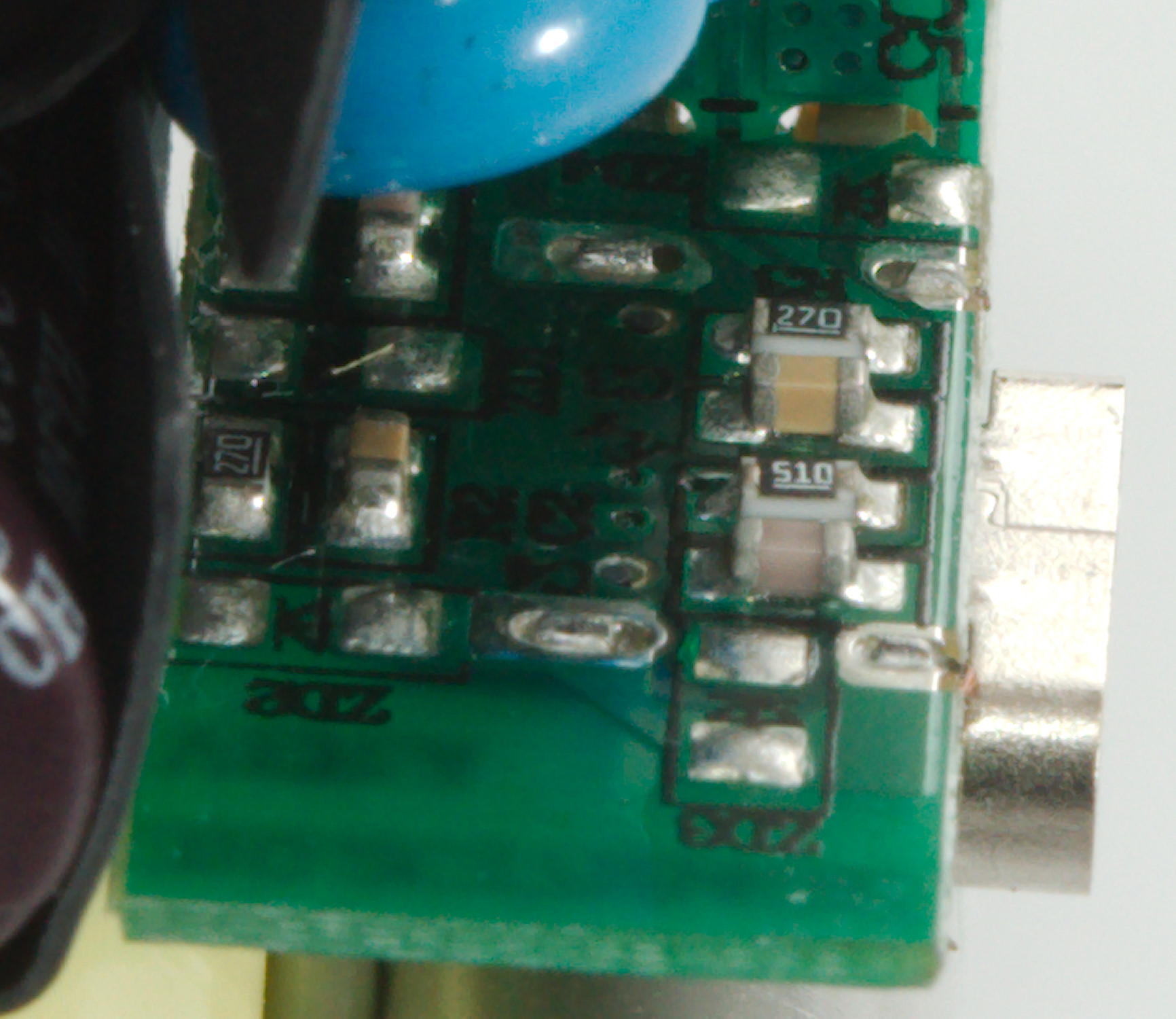
The small board with the usb connector, is has some capacitors and resistors on it.
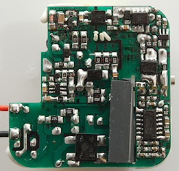
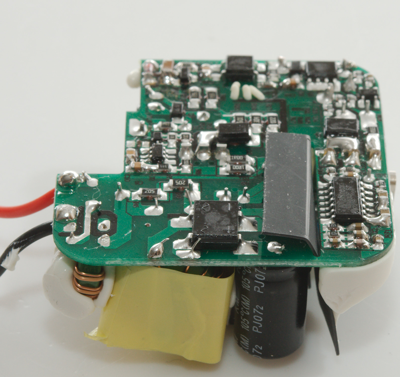
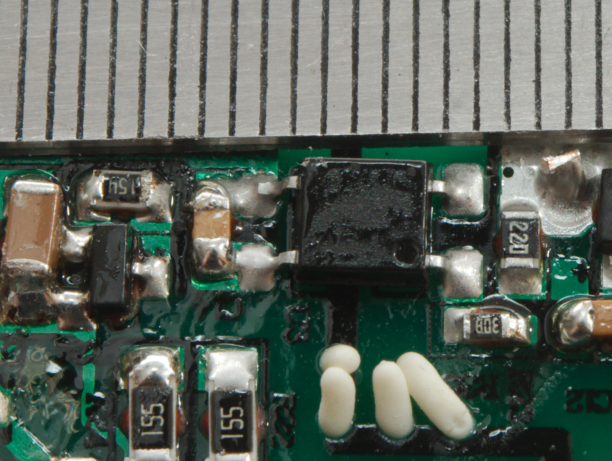
At the mains input is the bridge rectifier (BD1). The mains switcher is a 6 pin IC (U2). There is a opto coupler for feedback (U3). The rectification is done with a power mos (Q3) and a synchronous controller chip (U4). The USB PD and QC is handled by the larger chip (WT6632F) and it need a power mos to control the output (Q2). The 0.005ohm resistor (R005) is probably used to compensate for cable voltage drop and for current limiting.
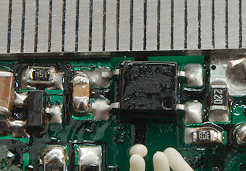
The isolation distance is a bit short at around 5.5mm
Testing with 2830 volt and 4242 volt between mains and low volt side, did not show any safety problems.
Conclusion
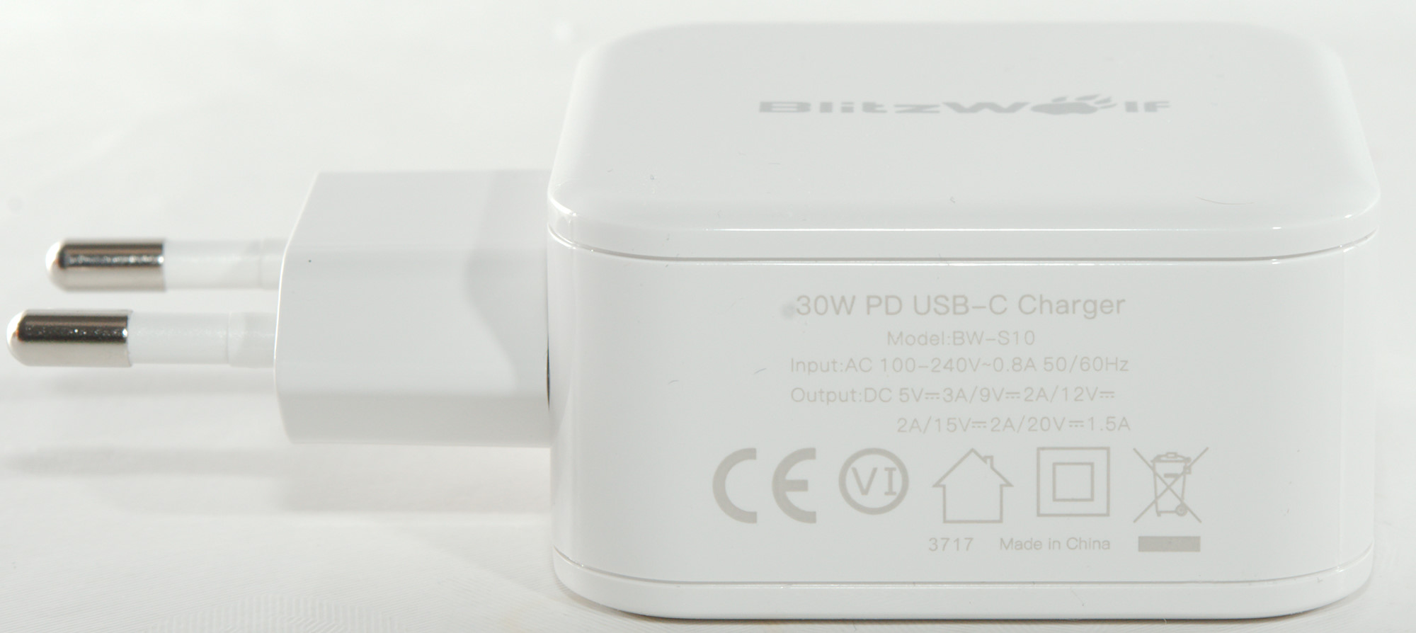
A nice USB-C PD charger with a good amount of power for phones and tablets, but markings on the charger do not match the specifications. The noise is low.
Notes
Index of all tested USB power supplies/chargers
Read more about how I test USB power supplies/charger
How does a usb charger work?