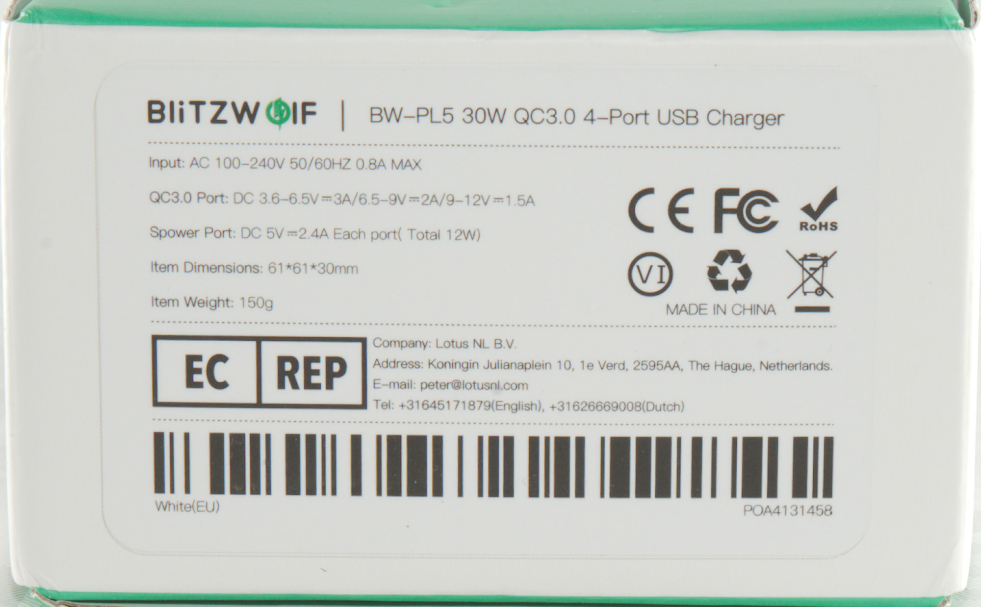
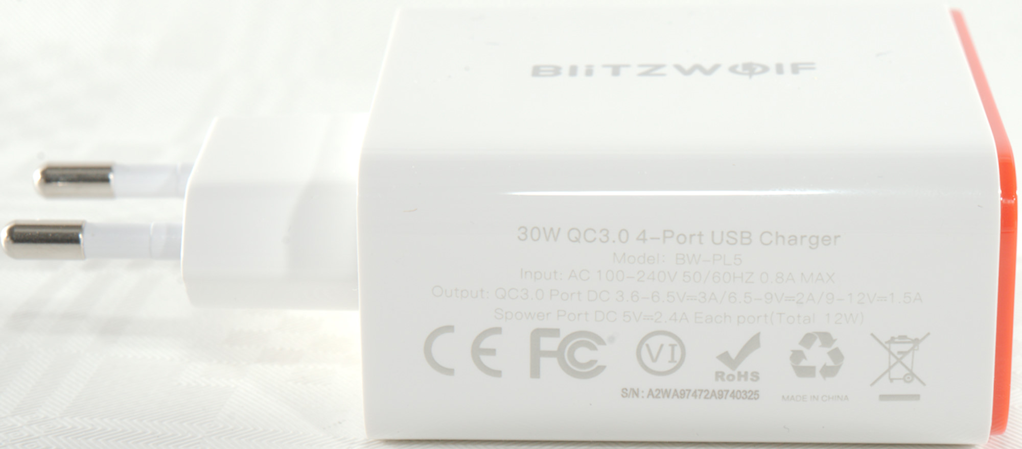
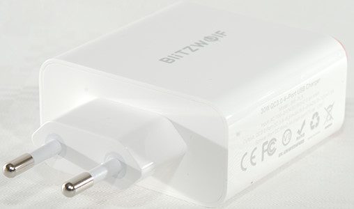
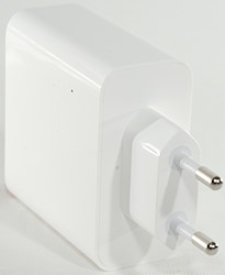
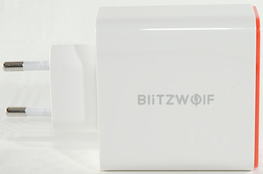
BlitzWolf 30W QC3 4 port USB Charger BW-PL5
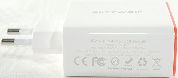
Official specifications:
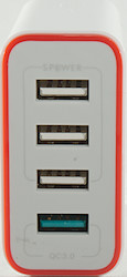
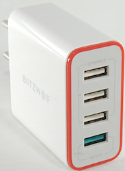
- USB Port: Four Ports USB
- Total Power: 30W (Max)
- Input: AC 100-240V 50/60HZ 0.8A MAX
- Output: QC3.0 Port DC 3.6-6.5V=3A/6.5-9V=2A/9-12V=1.5A
- Spower: Port DC 5V=2.4A Each port (Total 12W)
- Size: 61*61*30 mm
- Net Weight: 126g
I got it from Banggood
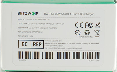
I got it in a small cardboard box with a label describing the contents.
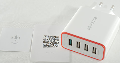
It contained the charger and a instruction sheet.
Measurements
- Power consumption when idle is 0.11 Watt
- Regular USB outputs is coded as Apple 2.4A
- Regular USB outputs are in parallel.
- QC and regular USB are not connected.
- There is a blue led between the regular USB outputs.
- QC output is coded as Apple 2.4A, QC3 and Huawei-FCP
- QC3 can go down to 4.4V, below it will reset.
- Weight: 108g
- Size: 96.5 x 61.0 x 30.0 mm
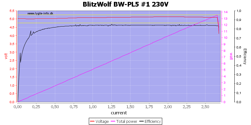
Output 1 can deliver a bit above 2.6A. There is some cable compensation (i.e. the output voltage will increase with load).

Output 3 can also deliver a bit above 2.6A
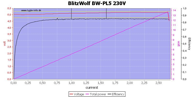
Using all 3 regular output is the same 2.6A
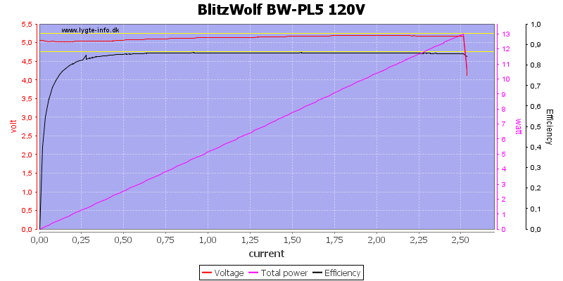
Output current is slightly less at 120VAC.
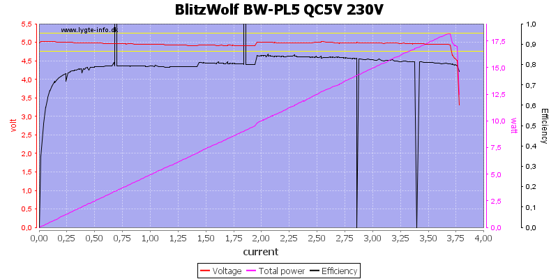
The QC output can deliver about 3.7A on 5V
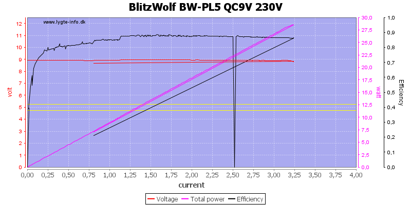
This is down to 3.2A at 9V
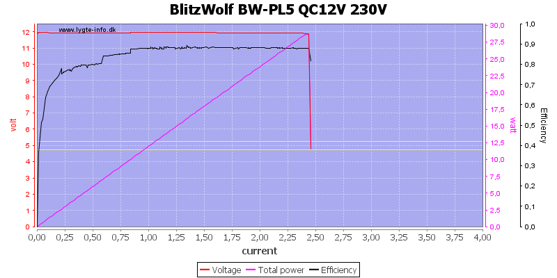
And about 2.5A at 12V, all well above the rated specifications.
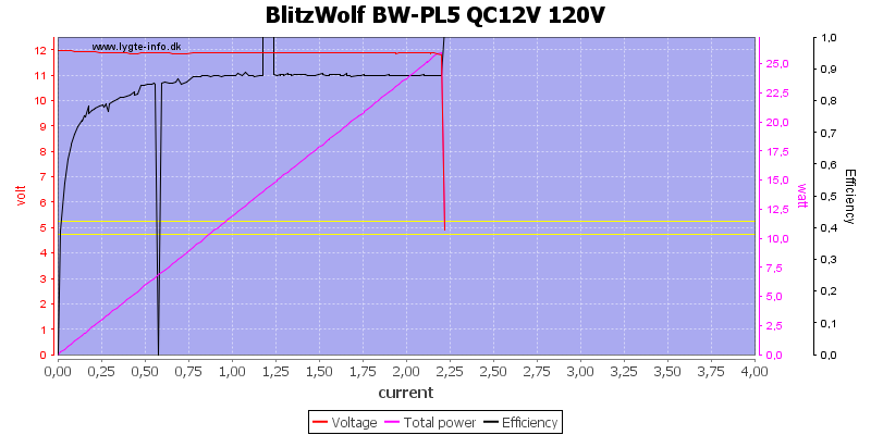
The maximum output current drops slightly at 120VAC, but is still well above specifications.
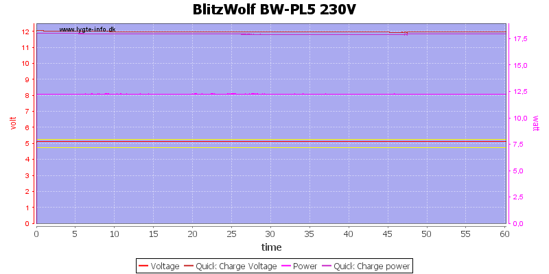
Running one hour with 5V 2.4A and 12V 1.5A worked fine.
The temperature photos below are taken between 30 minutes and 60 minutes into the one hour test.
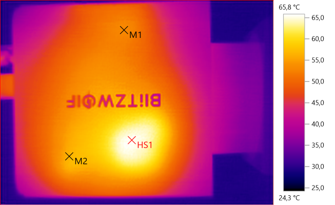
M1: 52.9°C, M2: 56.5°C, HS1: 65.8°C
HS1 is the regular USB transformer.
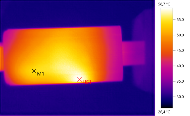
M1: 54.1°C, HS1: 58.7°C
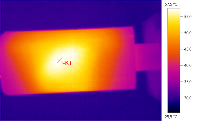
HS1: 57.5°C
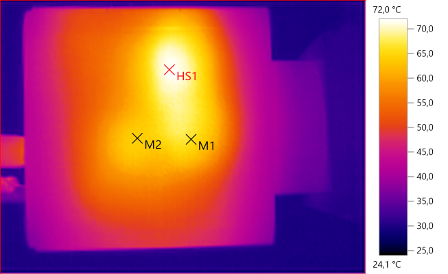
M1: 66.1°C, M2: 64.1°C, HS1: 72.0°C
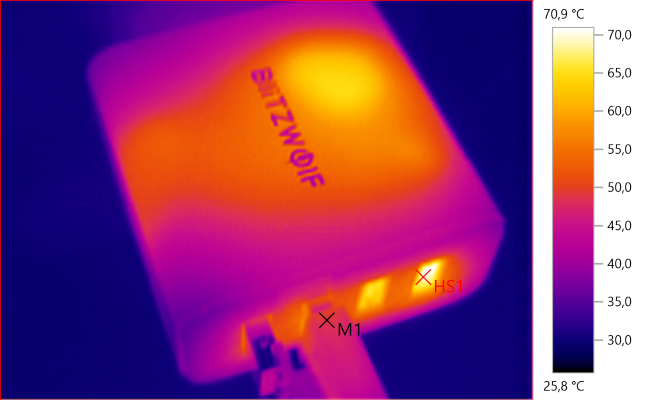
M1: 48.9°C, HS1: 70.9°C
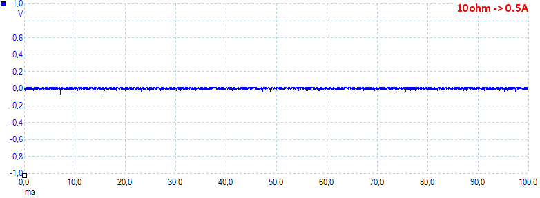
At 0.5A the noise is 7mV rms and 127mVpp.
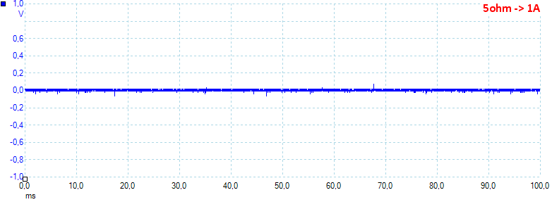
At 1A the noise is 9mV rms and 138mVpp.
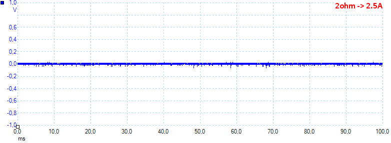
At 2.5A the noise is 10mV rms and 147mVpp.
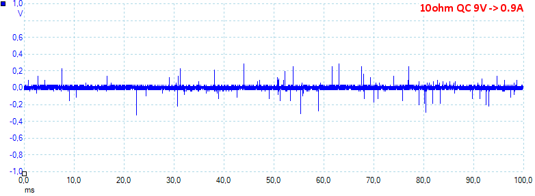
At 0.9A the noise is 26mV rms and 684mVpp.
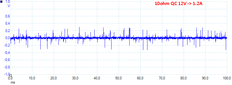
At 1.2A the noise is 31mV rms and 825mVpp.
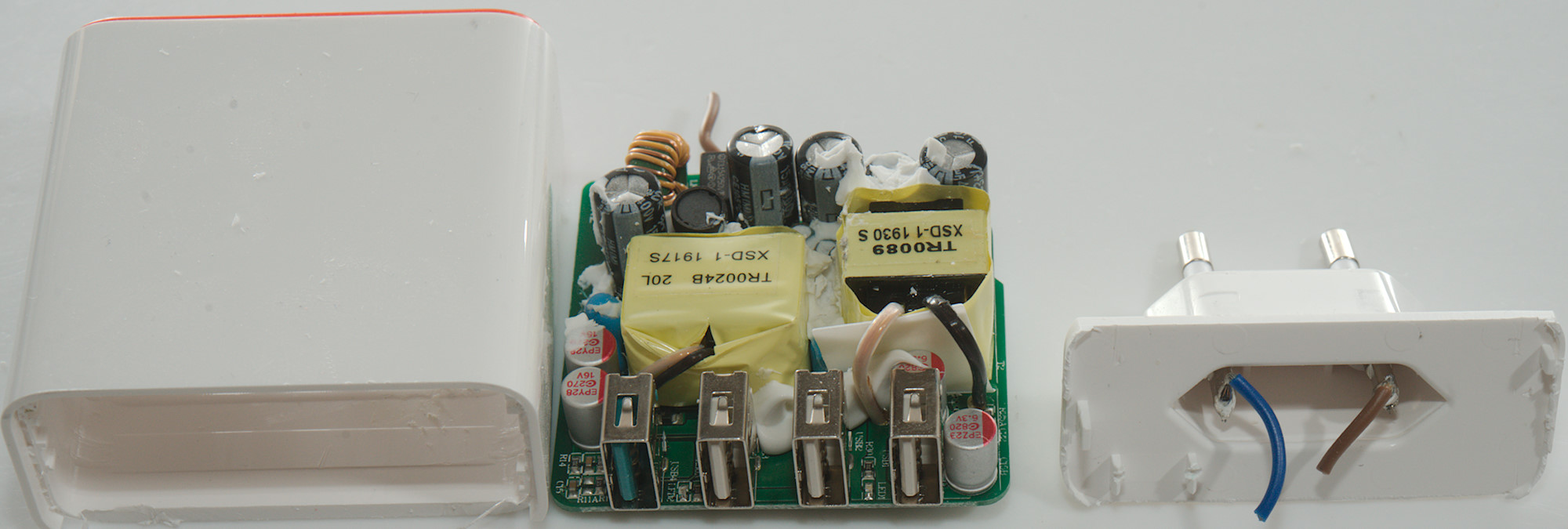
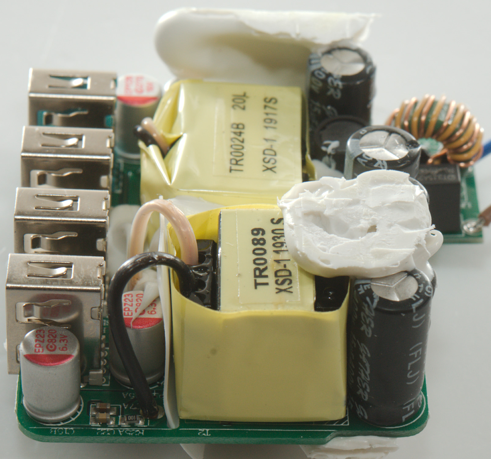
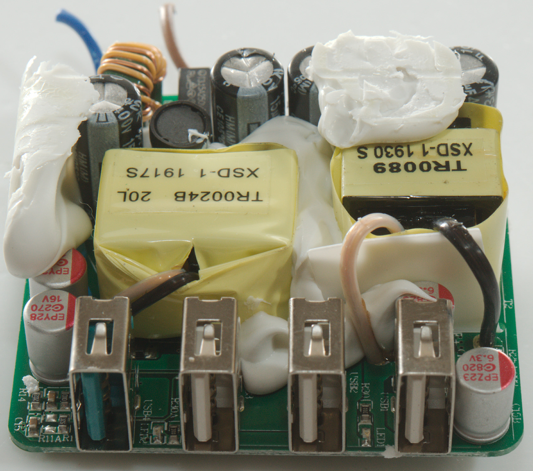
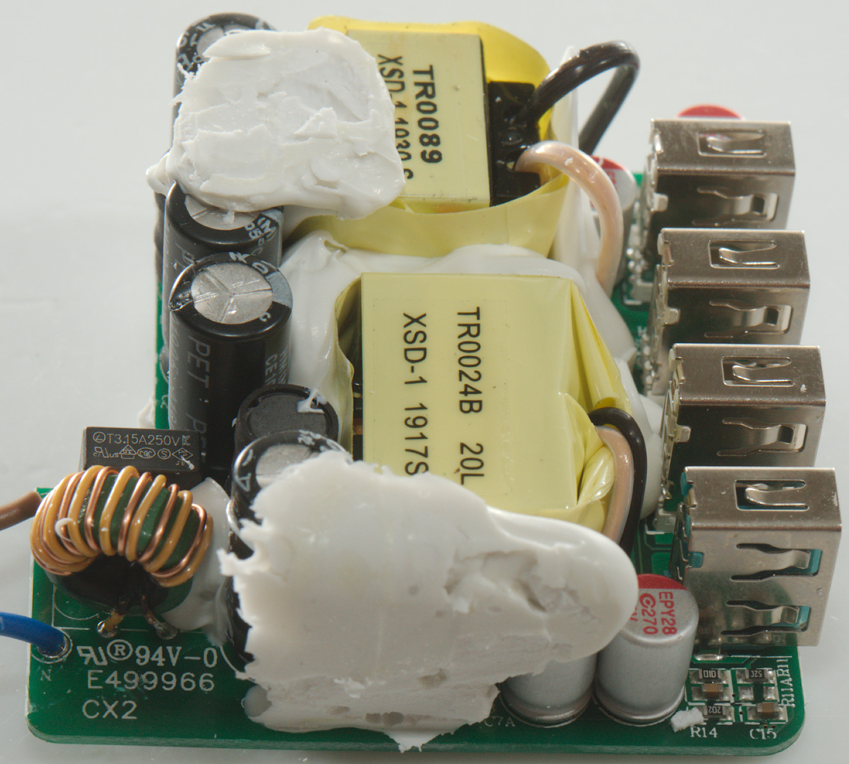
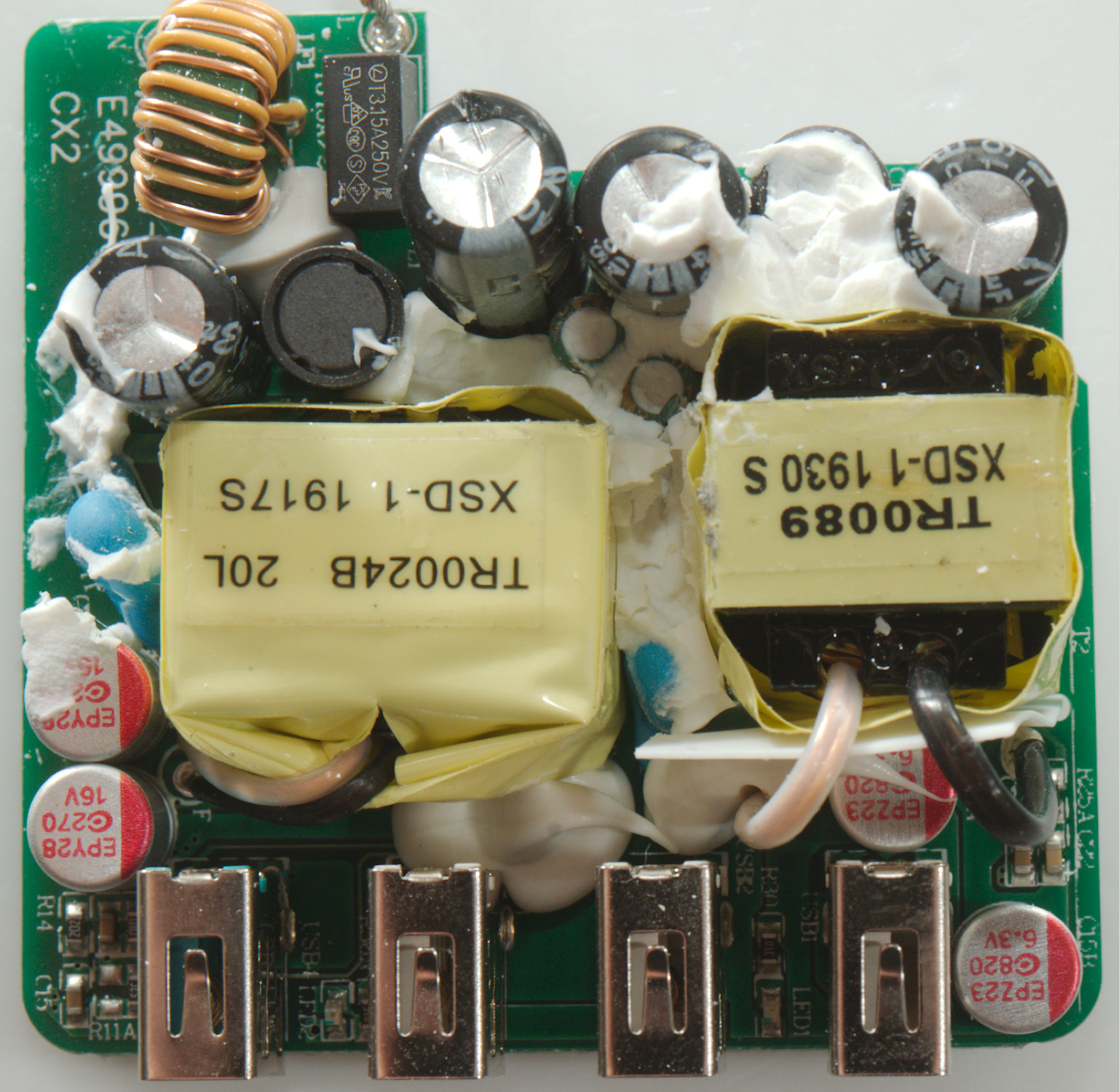
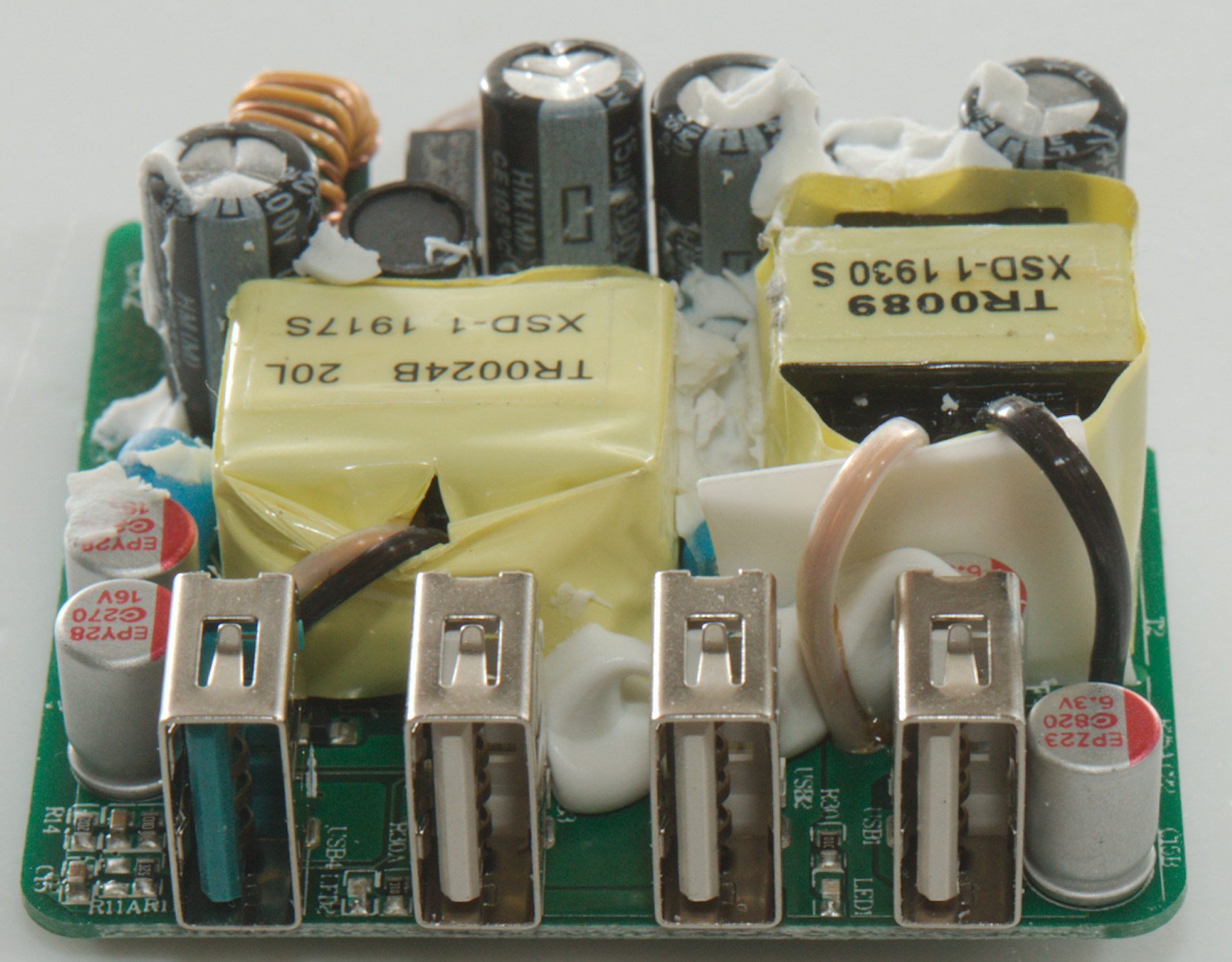
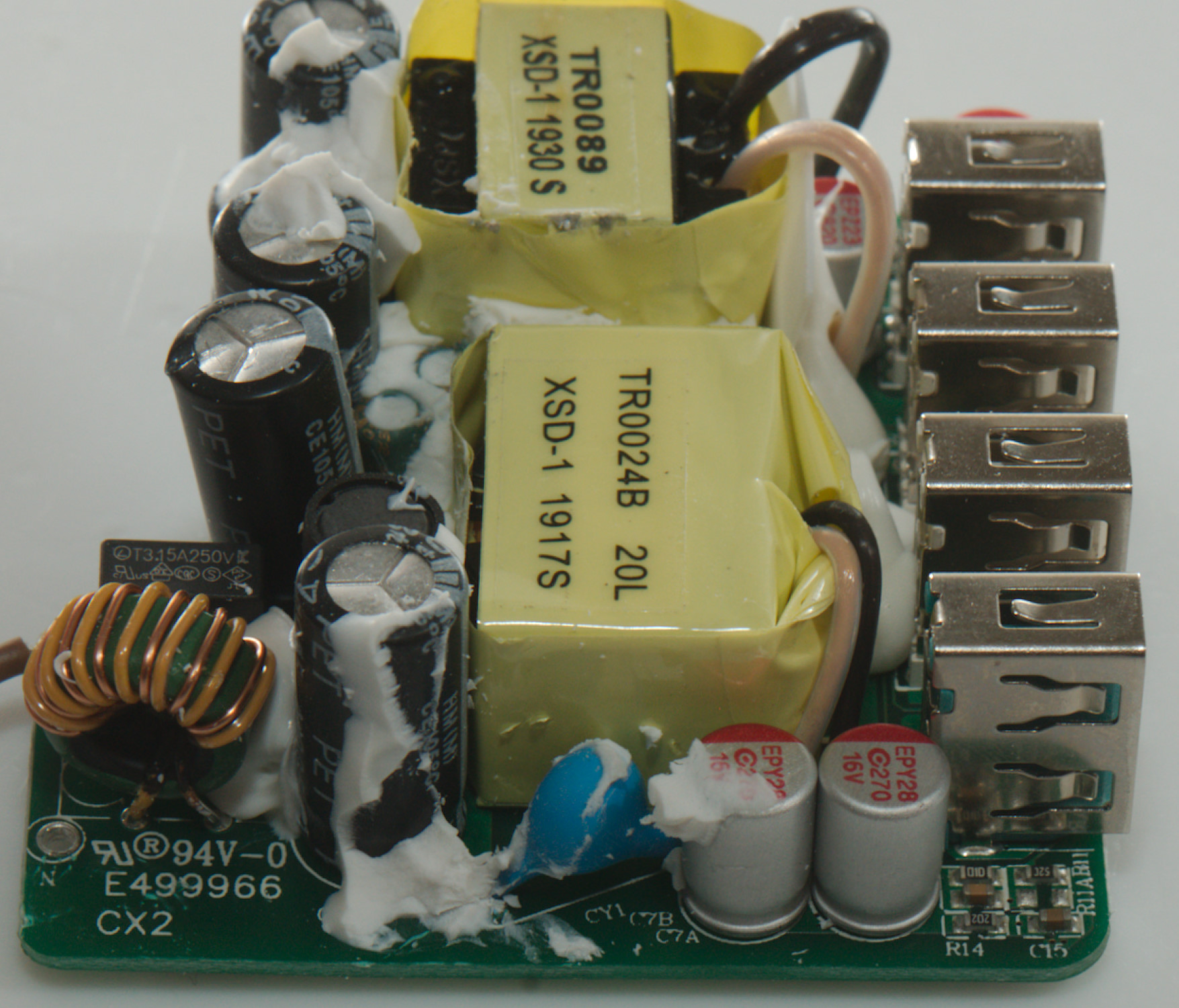
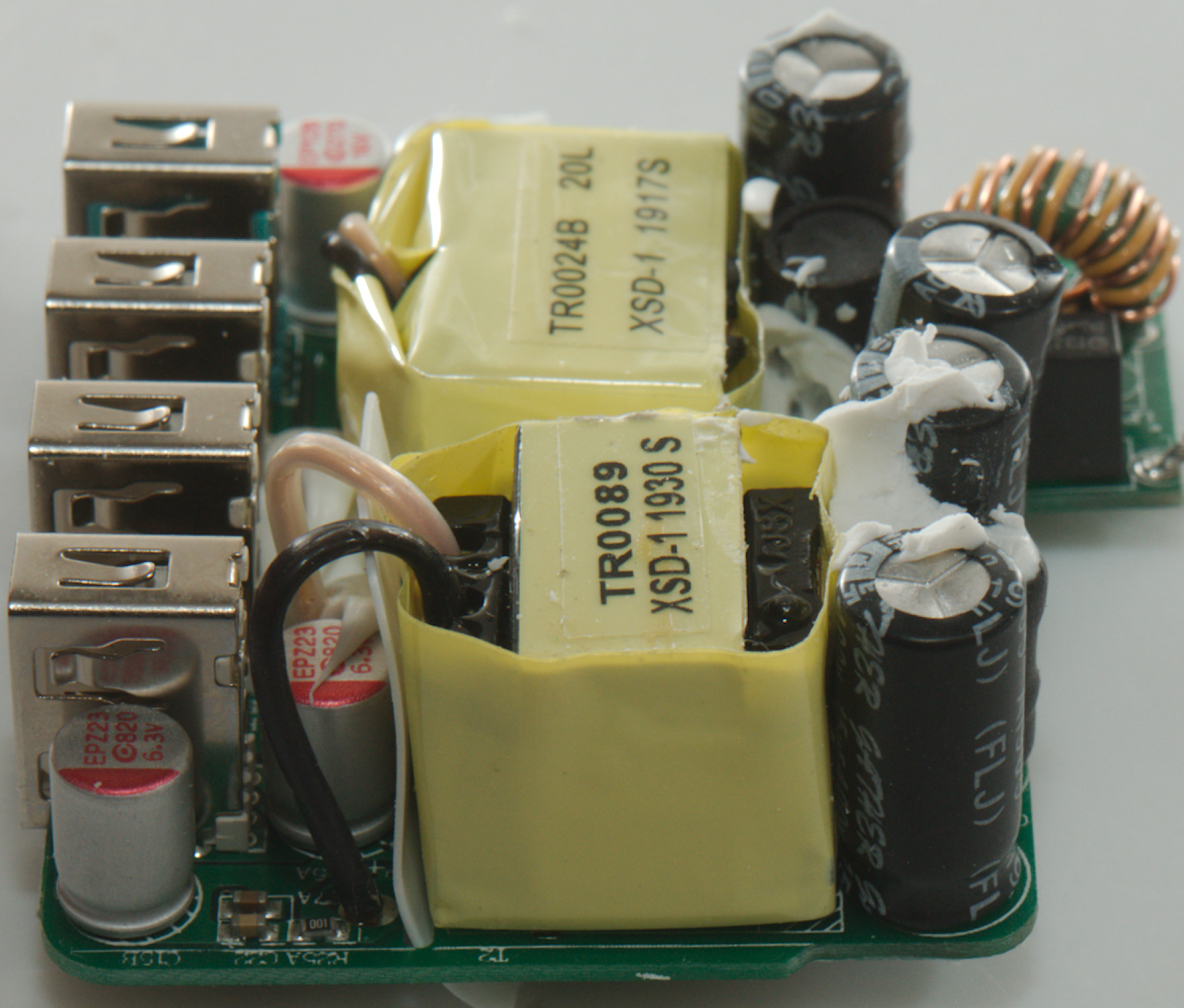
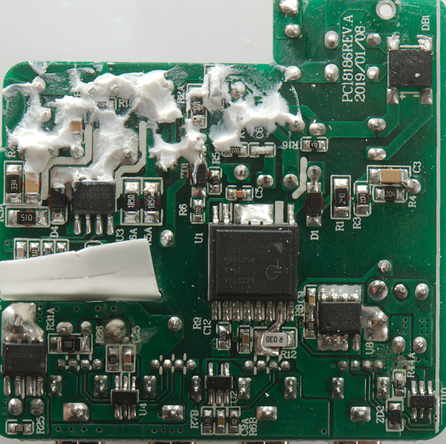
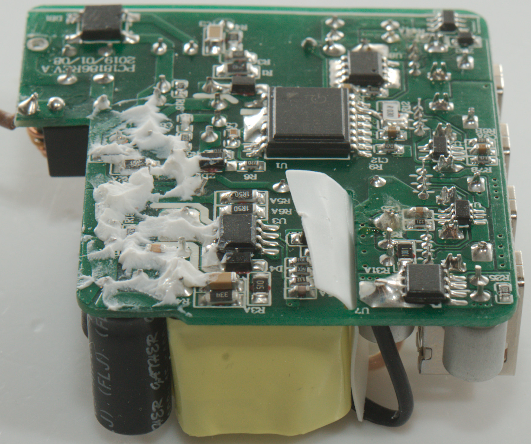
Tear down

I could not break this charger open, but had to cut a bit.
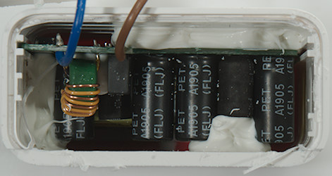
The electronic did not leave the charger easily either, there was a lot of the white stuff to keep it in.
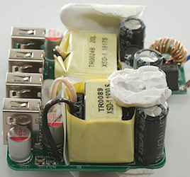

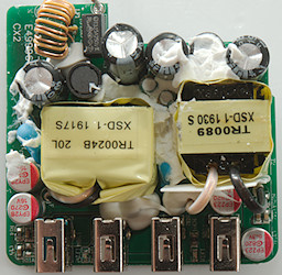
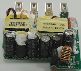
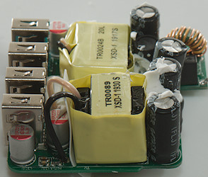
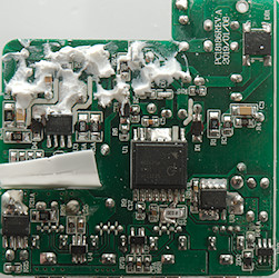
At the mains input is a fuse, followed by a common mode coil. there is two sets of mains smoothing capacitors each wit a inductor between them. These is also two safety capacitors, one for each transformer.
Between the USB connectors are some leds.
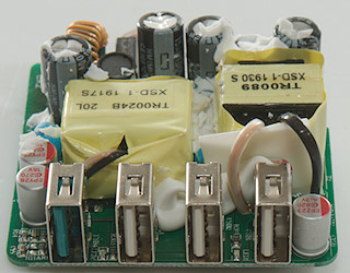

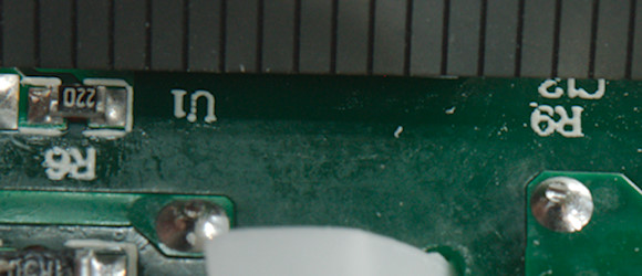
There is a production fault at the mains input, one of the wires are not soldered!
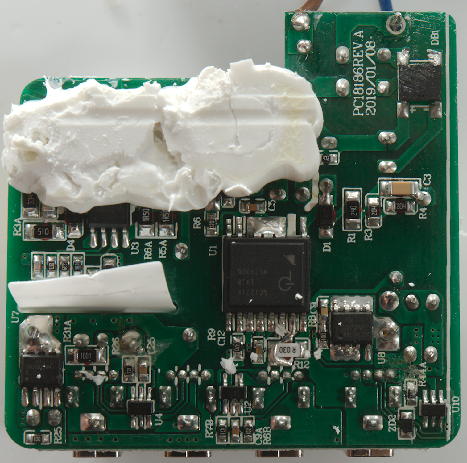
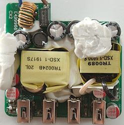
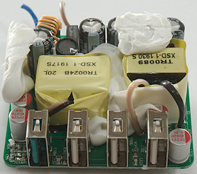
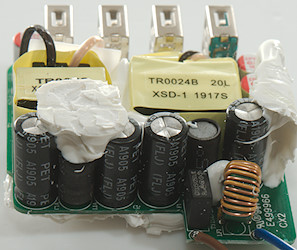
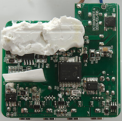
On this side is the bridge rectifier (BD1), there is two switcher IC's, for the regular USB output a small one (U3: OB2502) and for QC a larger all in one (U1: SC1271K). On the low volt side is a synchronous rectifier (U7: OB2005) for USB and the all in one chip only needs a MOS transistor for (U8: MOSFET HYG072N10 100V 80A) synchronous rectification. For the regular usb is two auto coding chip, a single (U2: Marked 1202) and a dual (U4: Marked 1212). The QC3 has its own control chip (U10: FT41).

There is good safety distance between low volt side and mains.
Testing with 2830 volt and 4242 volt between mains and low volt side, did not show any safety problems.
Conclusion
The charger works fine, but there is no reason for 3 regular USB outputs, the charger only has power for one! The QC output has more than enough power.
Except for the production fault (Missing solder) the charger looks good.
Notes
Index of all tested USB power supplies/chargers
Read more about how I test USB power supplies/charger
How does a usb charger work?