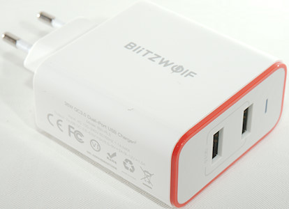
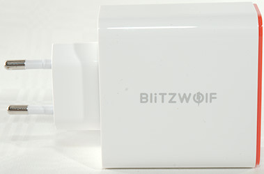
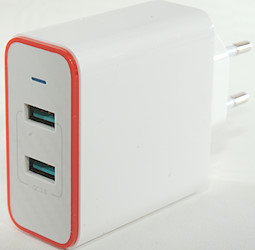
BlitzWolf 36W Quickcharger BW-PL3
Official specifications:
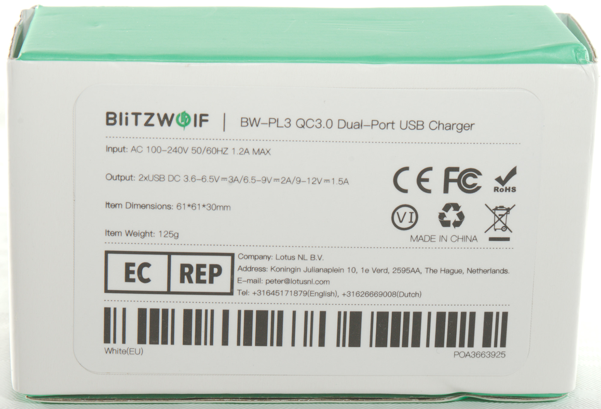
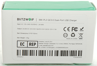
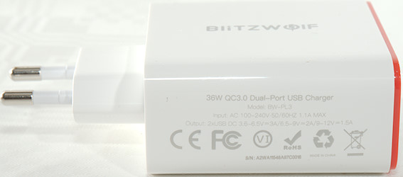
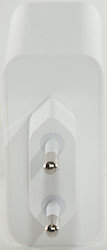
- Input voltage: 100-240V 50/60Hz
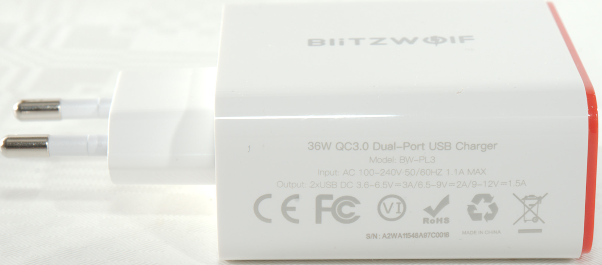
- Output: 2x 3.6-6.5V 3A, 6.5-9V 2A, 9-12V 1.5A
- Output power: 36 Watt
- Dimensions: 61 x 61 x 30mm
- Weight: 125g
I got it from Aliexpress dealer: BlitzWolf Official Store
Measurements
- Power consumption when idle is 0.13 Watt
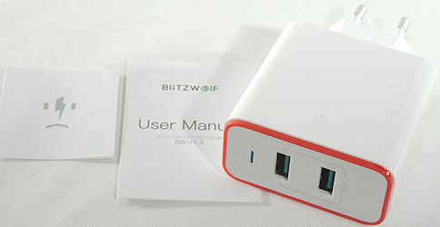
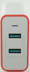
- USB output is auto coding with Apple 2.4A, DCP and QC3
- Minimum QC3 voltage is 4.3V, will reset when lower voltage is selected
- There is a blue led above the USB connectors.
- Minus is common for the two USB outputs.
- Weight: 108.4g
- Size: 96.5 x 61.0 x 30.0mm

The overload protection kick in at 3.5A, this is fine for a 3A charger.
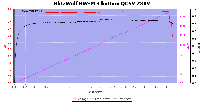
The other output is the same.
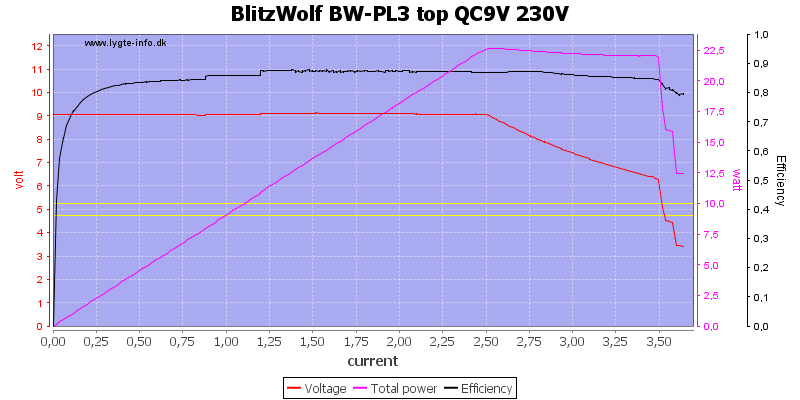
THe 9V output can deliver 2.5A, but the overload protection first kick in at 3.5A.
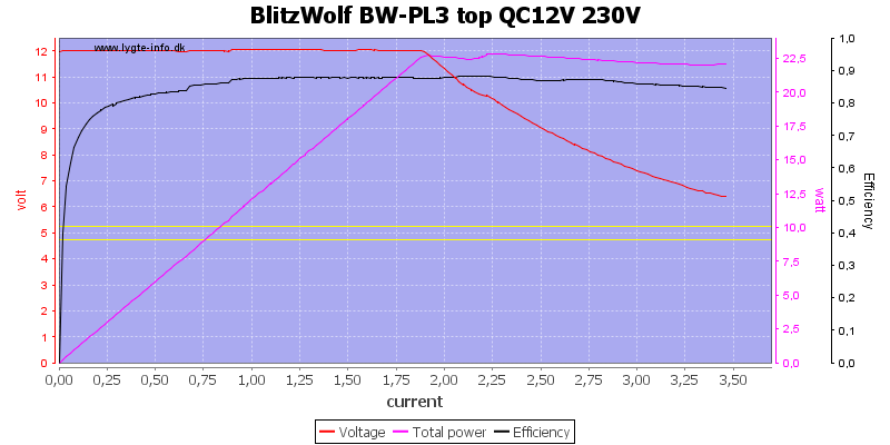
At 12V the charger can deliver 1.8A, but again the overload protection first kick in at 3.5A
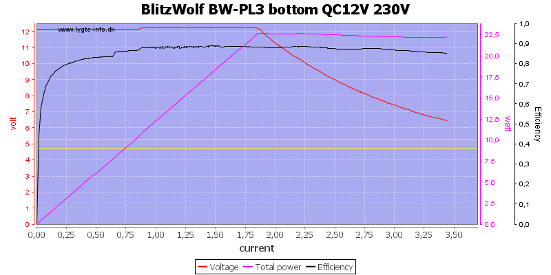
The other output is the same.
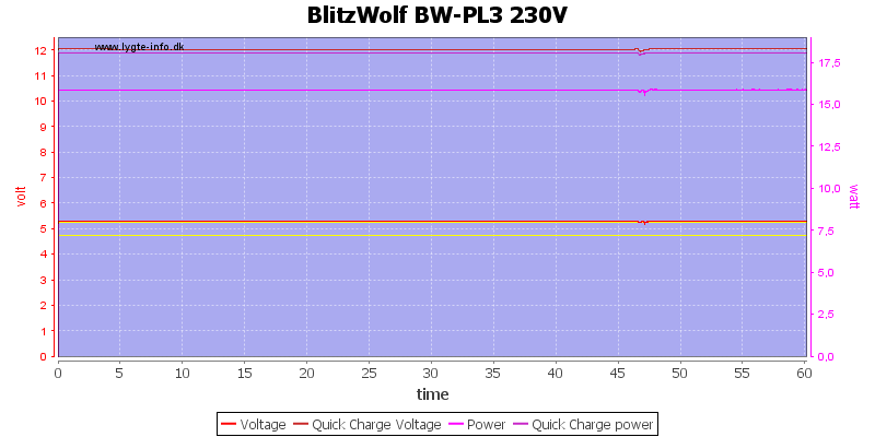
For output test I runt one output at 5V 3A and the other at 12V 1.5A and the charger could maintain that for one hour.
The temperature photos below are taken between 30 minutes and 60 minutes into the one hour test.
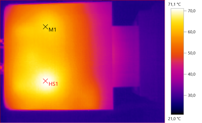
M1: 64.1°C, HS1: 71.1°C
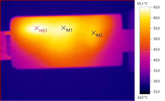
M1: 63.2°C, M2: 57.5°C, HS1: 65.1°C
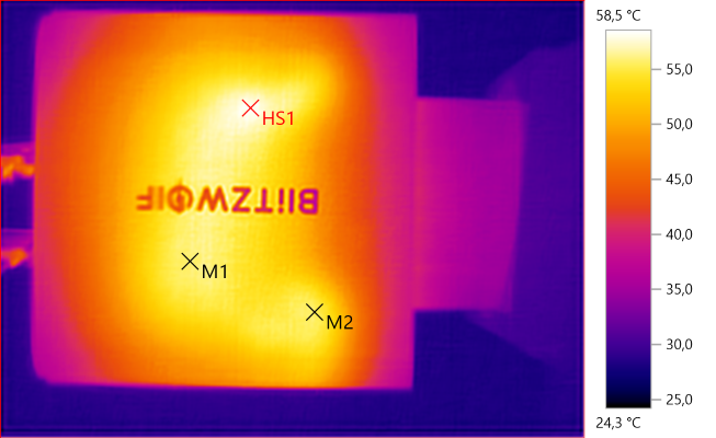
M1: 55.9°C, M2: 55.6°C, HS1: 58.5°C
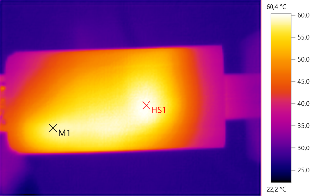
M1: 58.1°C, HS1: 60.4°C
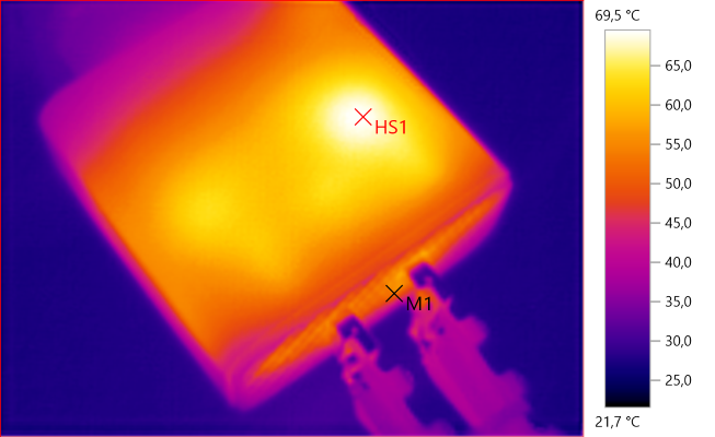
M1: 53.1°C, HS1: 69.5°C
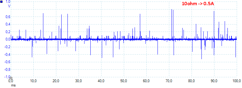
At 0.5A the noise is 43mV rms and 1421mVpp.
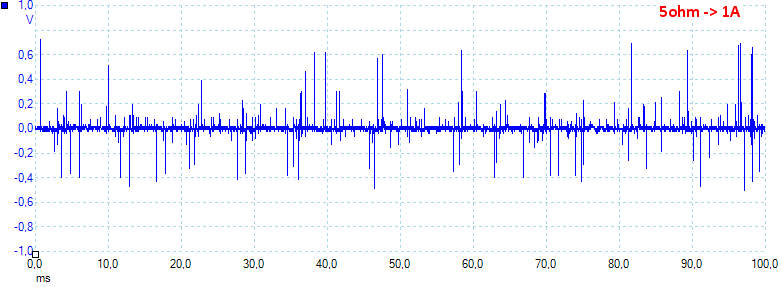
At 1A the noise is 47mV rms and 1509mVpp.
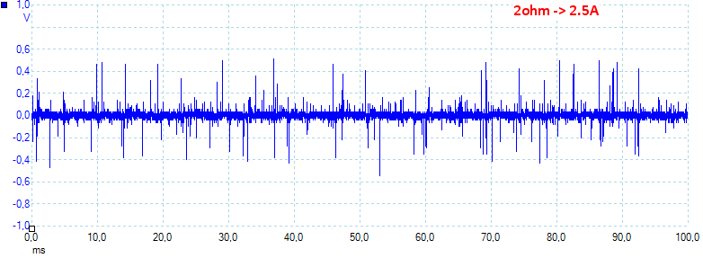
At 2.5A the noise is 55mV rms and 1765mVpp.
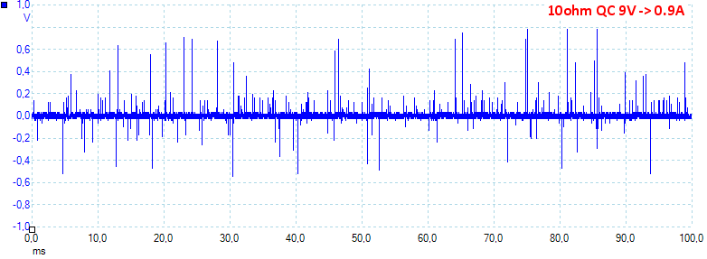
At 0.9A the noise is 52mV rms and 1606mVpp.
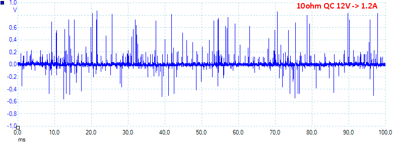
At 1.2A the noise is 72mV rms and 1738mVpp.
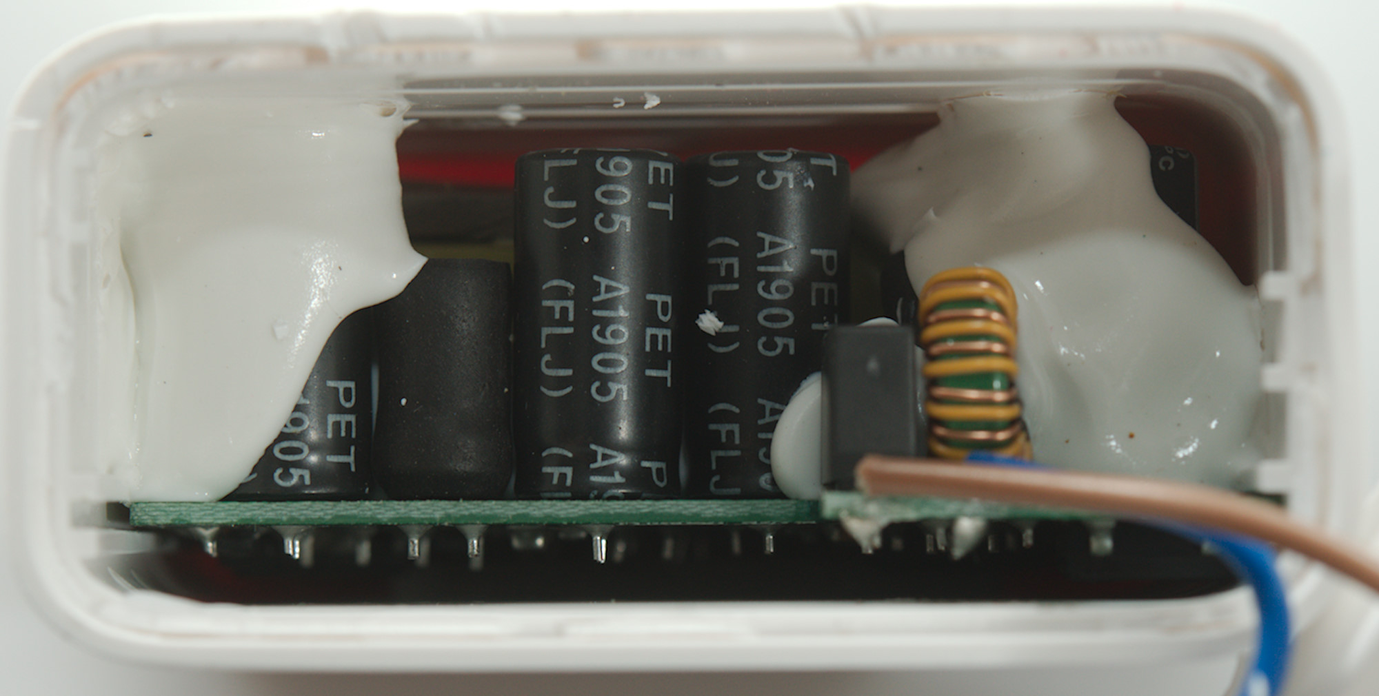
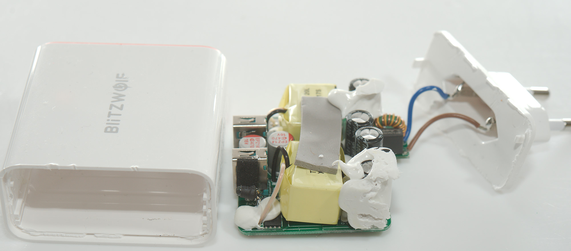
Tear down
This can make it hard to get the circuit board out.
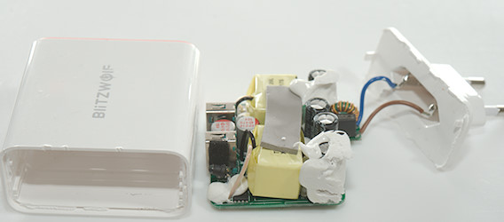
Mounting the base in my vice I could break the top off with my mallet and the circuit board was not that hard to get out.
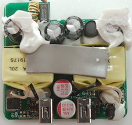
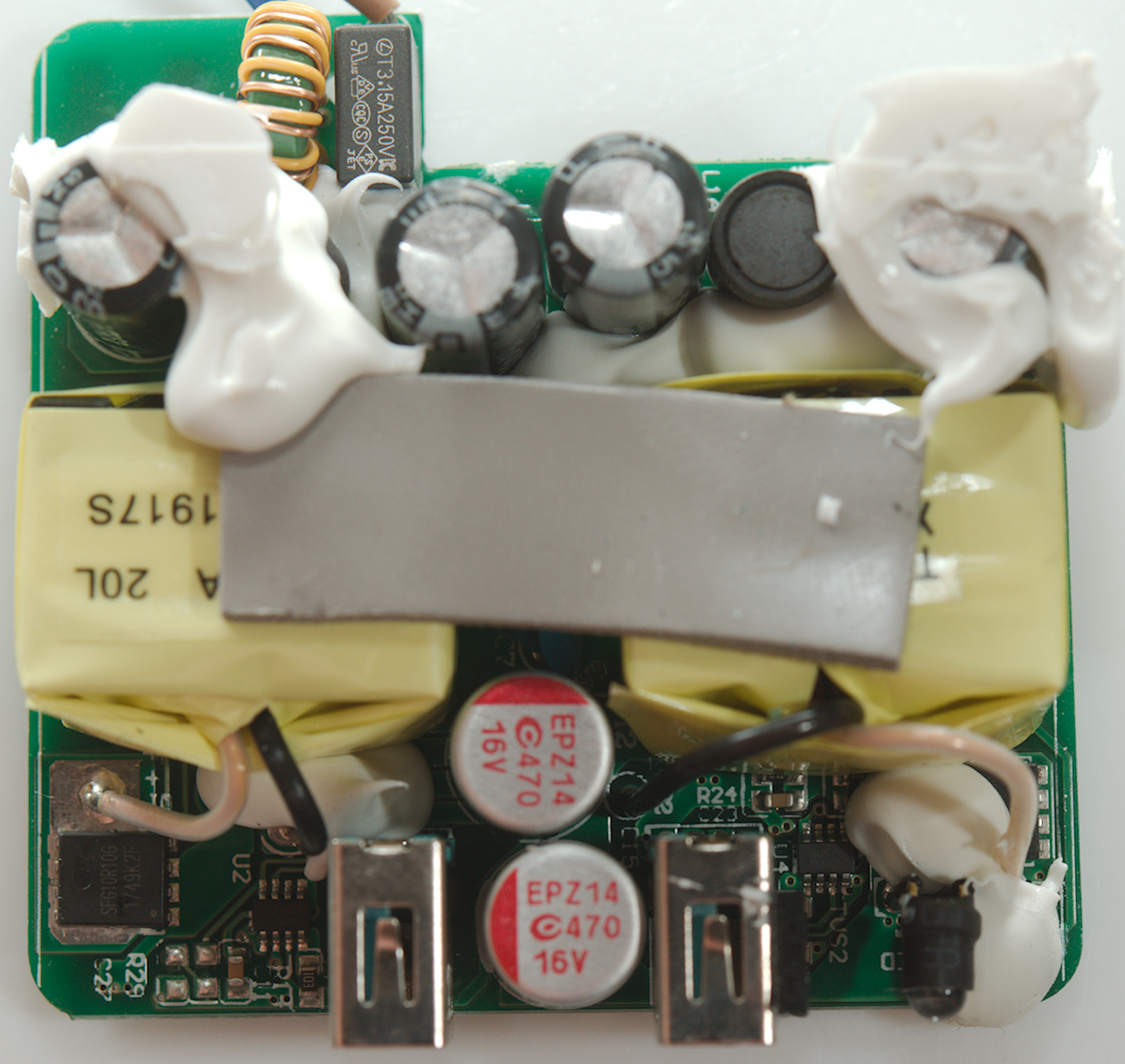
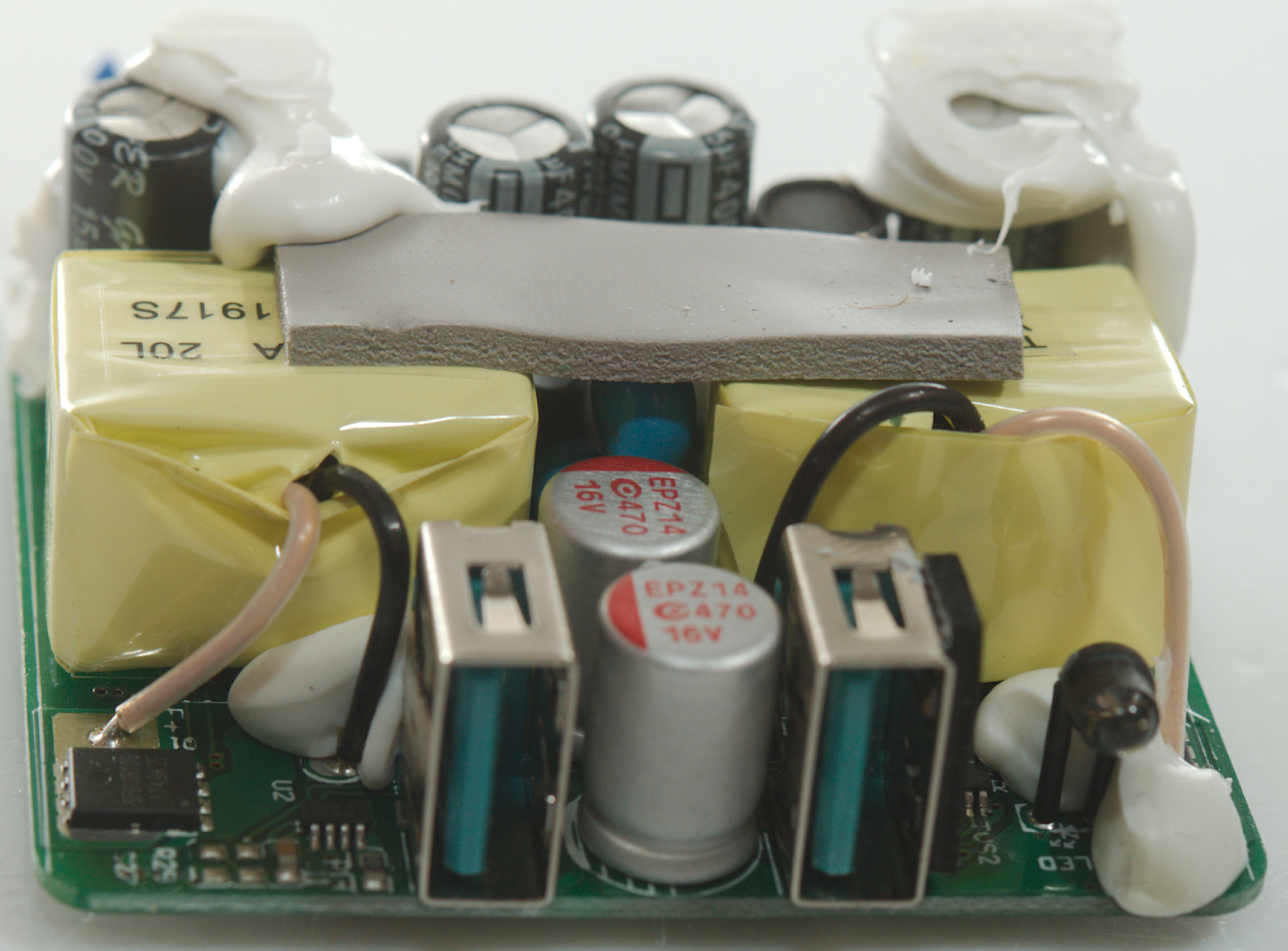
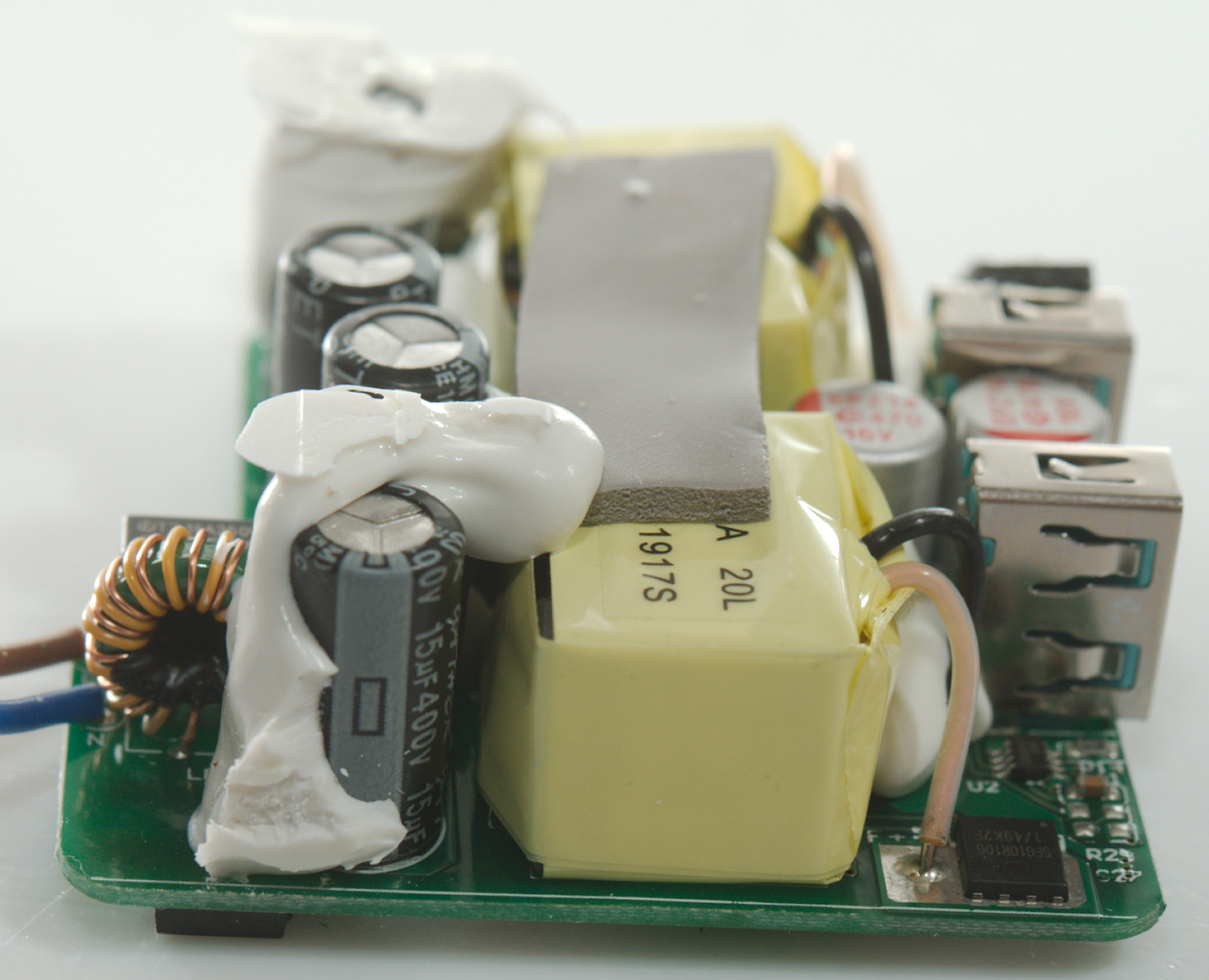
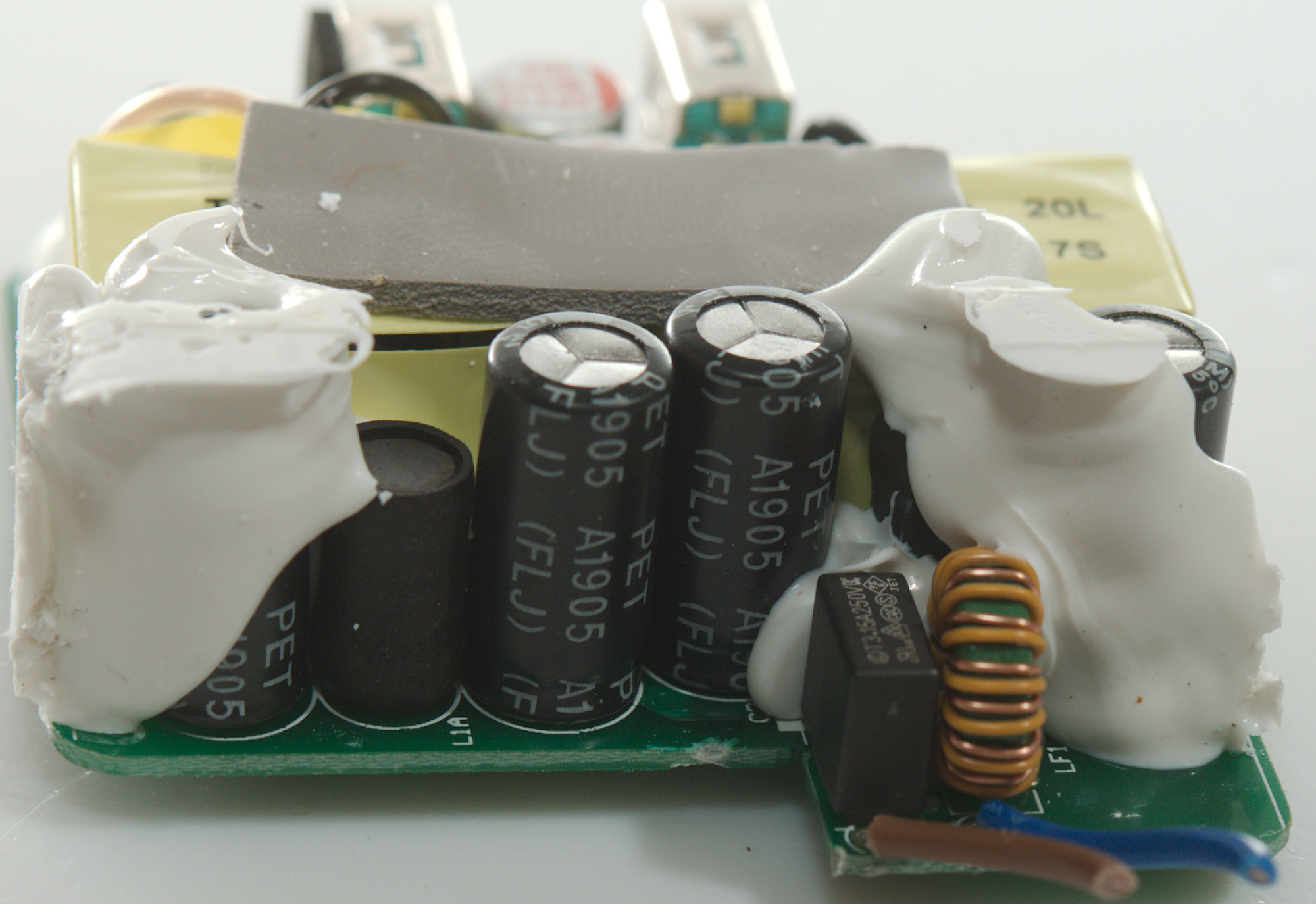
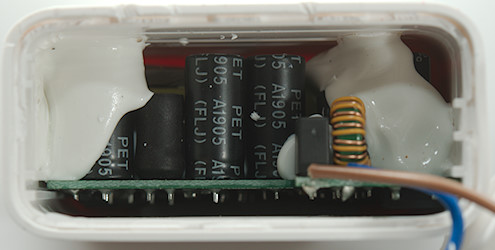
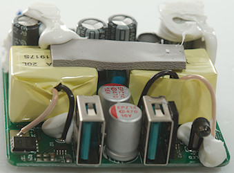
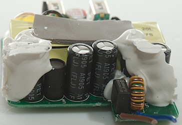
At the input is a fuse, then a common mode coil, there is 4 smoothing capacitors with a inductors (L1 && L?) between them (Each switcher has a inductor and capacitor). Between the transformers are two safety capacitors, one for each USB output.
On the low volt side is some large mosfets (SFG10R10G) for synchronous rectification. Each output also has a QC controller (U2 & U4: Marked N06 / PJK953)
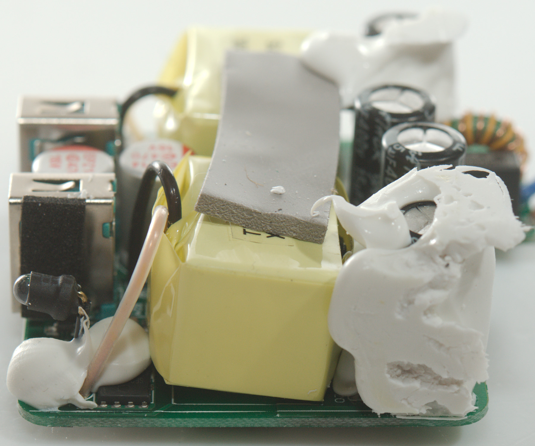
Why is there a heat transfer pad on top of the transformers, it do not touch the enclosure as can be seen on the white stuff that goes well above it.

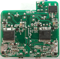
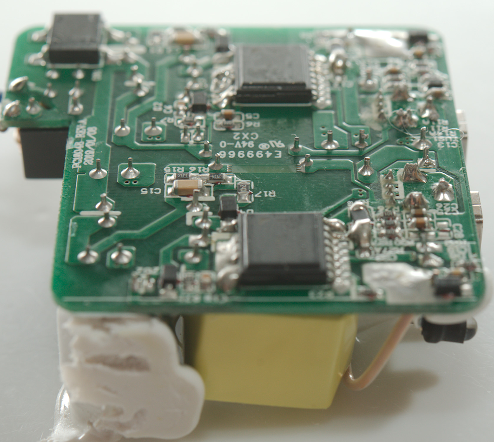
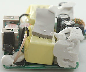
On this side is the bridge rectifier and two advanced mains switchers (U1 & U3: INN2215k).
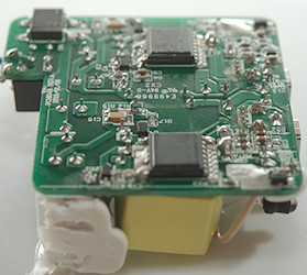
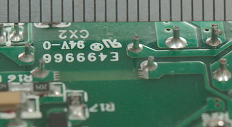
The distance between mains and low volt side is large enough.
Testing with 2830 volt and 4242 volt between mains and low volt side, did not show any safety problems.
Conclusion
A dual QC3 charger with a lot of power. It is is a nice design with two mostly independent QC supplies, but also some issues. The QC3 cannot go much below 5V and there is a lot of noise (probably common mode).
Notes
The USB charger was supplied by a reader for review.
Index of all tested USB power supplies/chargers
Read more about how I test USB power supplies/charger
How does a usb charger work?