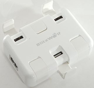
BlitzWolf usb charger BW-S4
Official specifications:
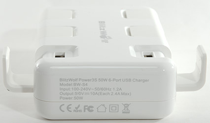
- Model: BW-S4
- Power: 50W
- Input: 110-240V,50/60Hz 1.2A
- Output: 5V, 10A ( Each 2.4A Max)
- Size: 98*69*30mm/3.85"*2.71"*1.18"
- Weight: 205g
- Color: White
I got it from a Banggood

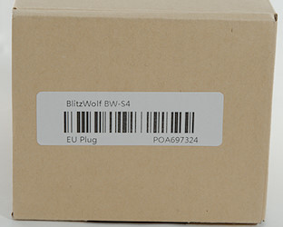
It was in a brown cardboard box, but the box may have changed since I bought it.
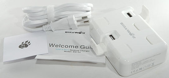
The box contains the charger, a mains cord and a instruction sheet
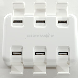
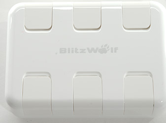
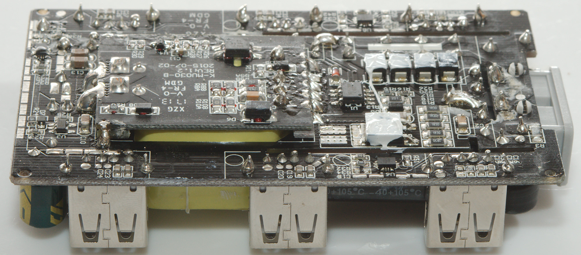
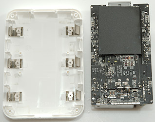
There is 6 usb output with a lid for each one.

Measurements
- All outputs are auto detect.
- Power consumption when idle is 0.08 watt
- Output minus are in parallel.
- Output plus has a over current protection for each output.
- Weight: 202g without mains cable.
- Size: 100 x 70 x 30mm

Port #1 can deliver about 2.7A before overload protection trips.
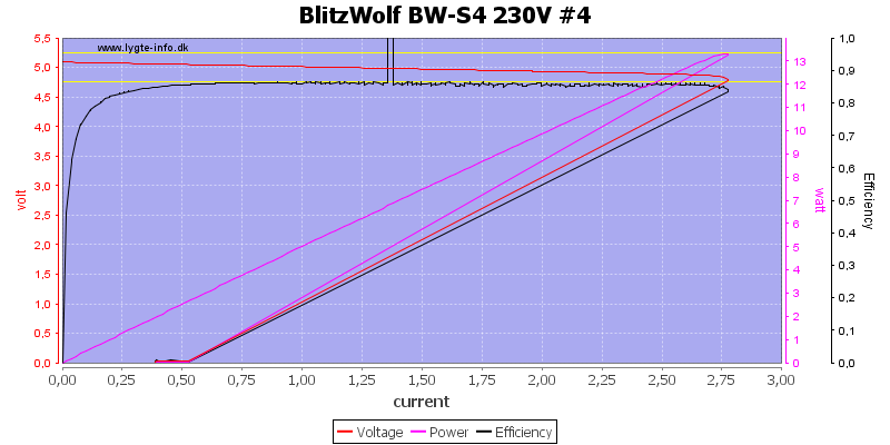
The same for port #4
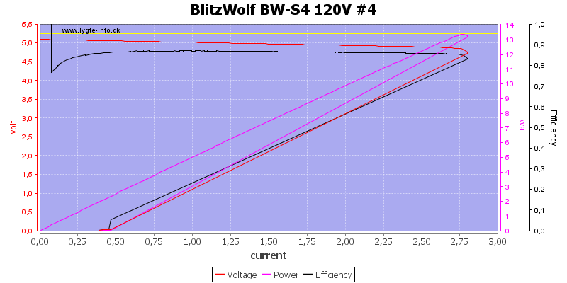
Using 120VAC do not change anything, even the efficiency is basically the same.
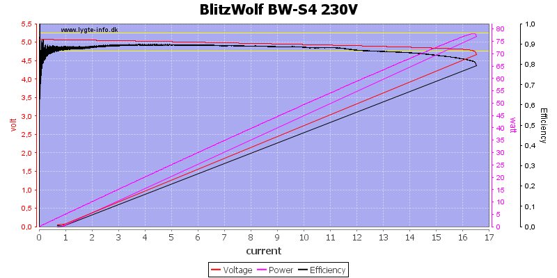
Running all port in parallel shows that it can deliver considerable more current than the rating, the result is about 2.7A*6 or 16.5A before overload protection trips.
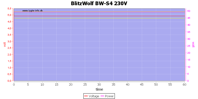
No problems running one hour at 5V 10A.
The temperature photos below are taken between 30 minutes and 60 minutes into the one hour test.
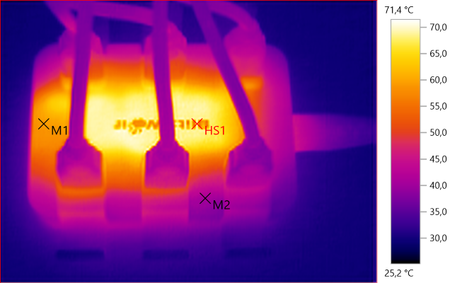
M1: 59,1°C, M2: 40,8°C, HS1: 71,4°C
Due to the metal a large part of the top has the same temperature.
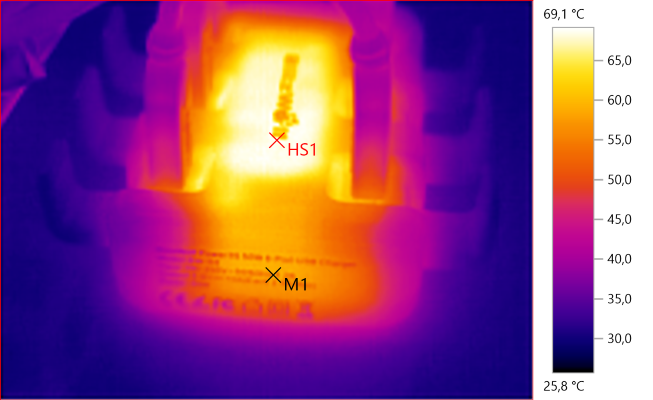
M1: 58,5°C, HS1: 69,1°C
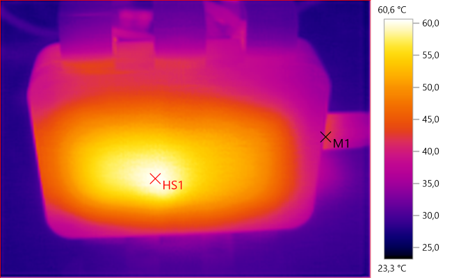
M1: 42,2°C, HS1: 60,6°C
HS1 is the transformer, the metal plate has a lower temperature over a larger area.
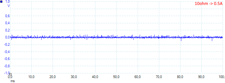
At 0.5A the noise is 12mV rms and 232mVpp
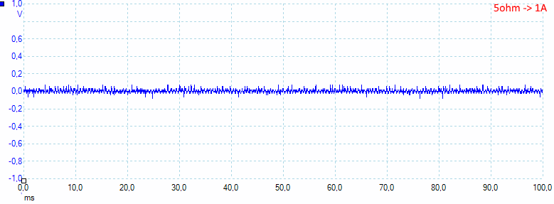
At 1A the noise is 14mV rms and 182mVpp
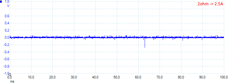
At 2.5A the noise is 14mV rms and 164mVpp.
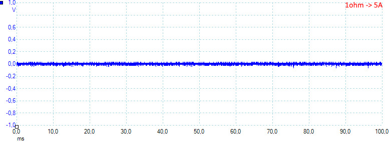
At 5A the noise is 17mV rms and 90mVpp.
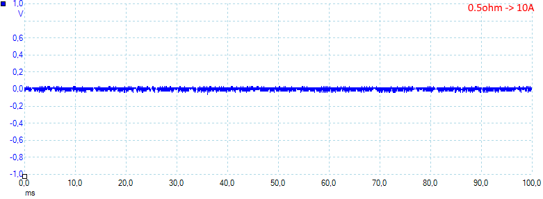
At 10A the noise is 20mV rms and 106mVpp, this is generally very low values.
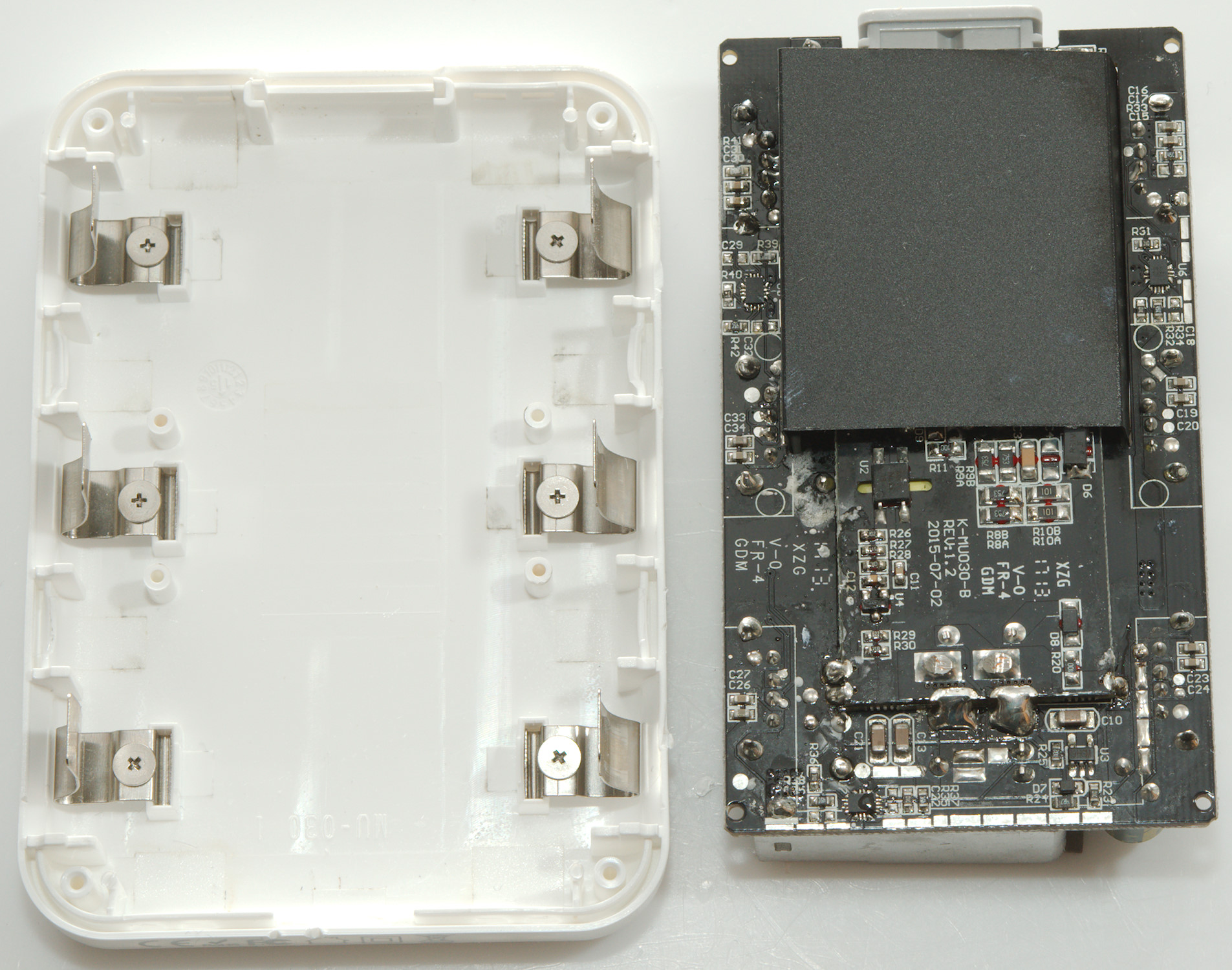
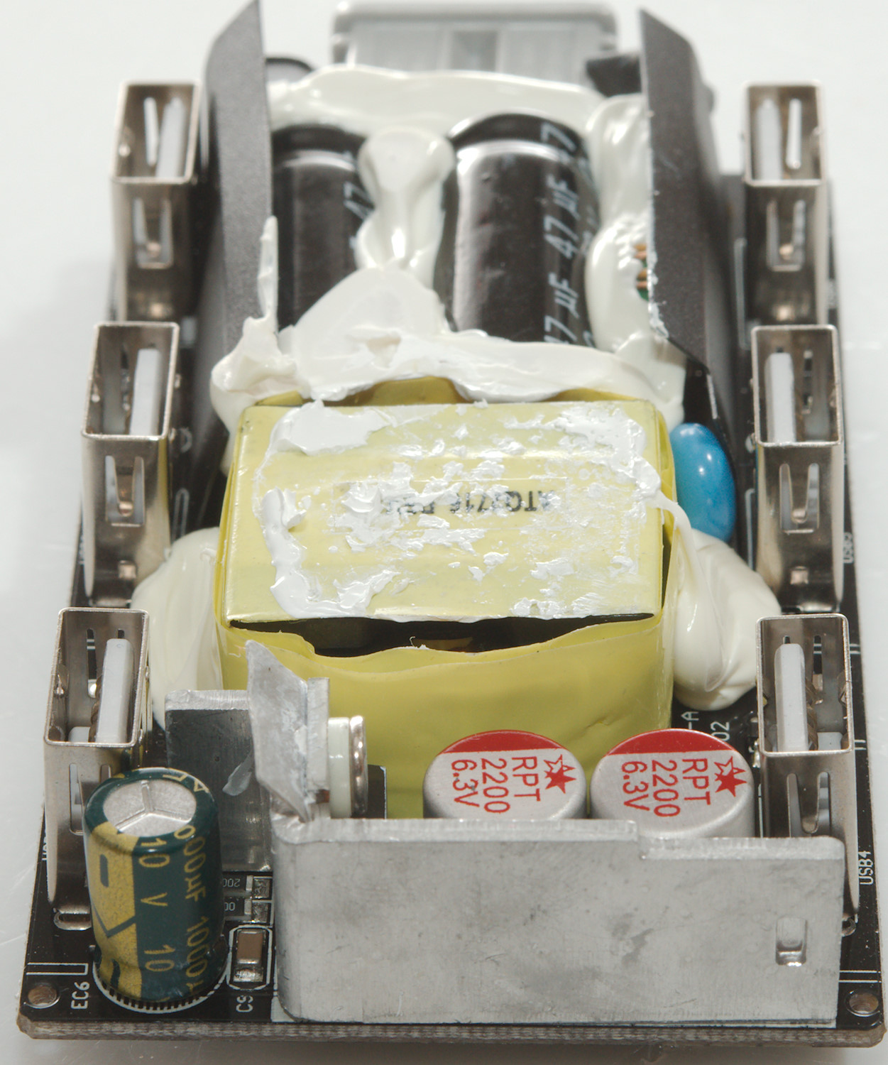
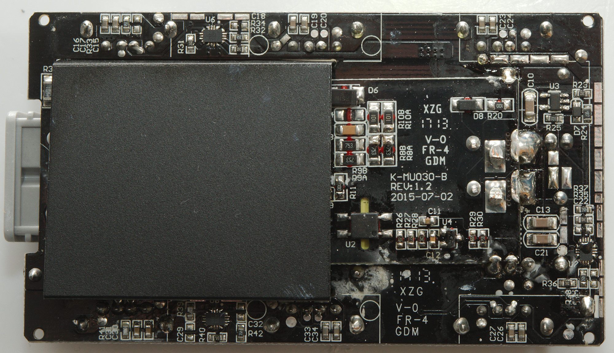
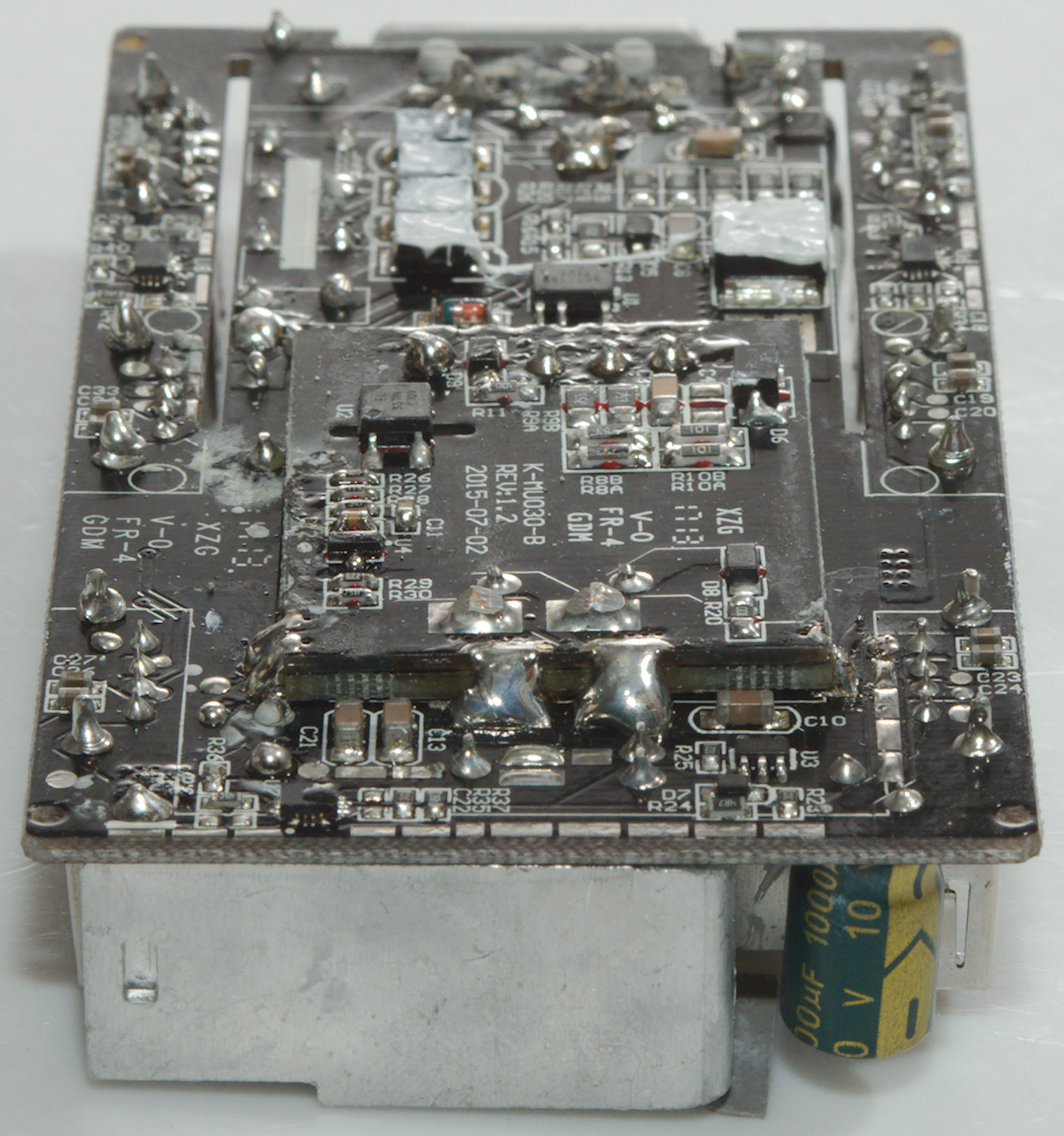
Tear down
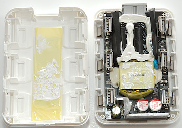
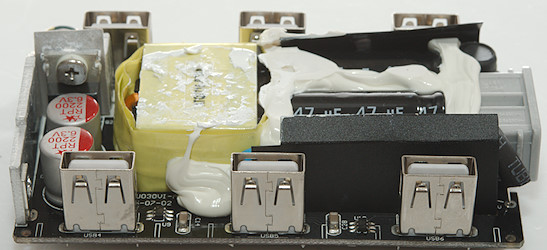
Pressing the box a bit with my vice and I could break it apart with a screwdriver. Behind the yellow tape in the lid is some metal to spread the heat from the transformer.

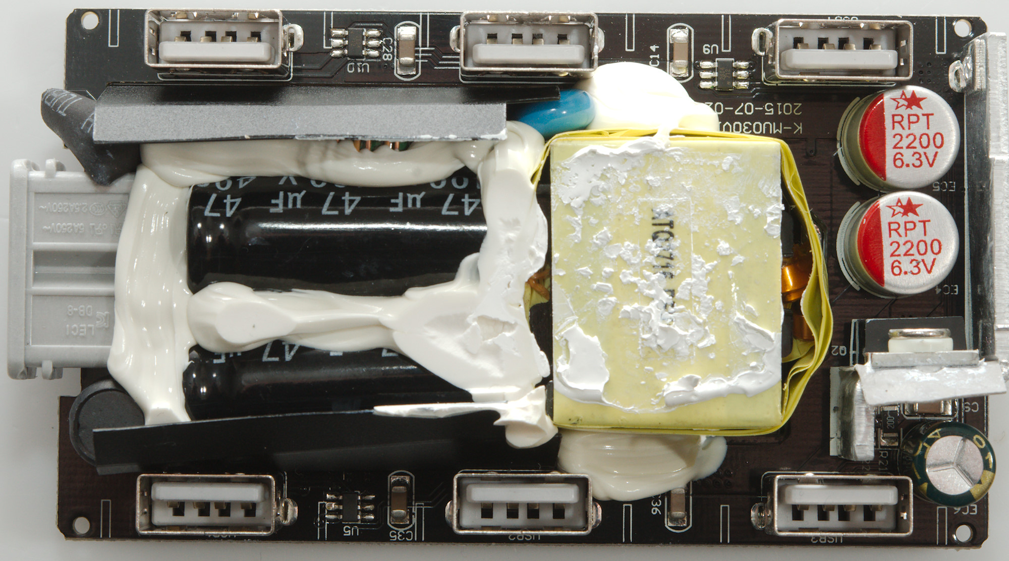
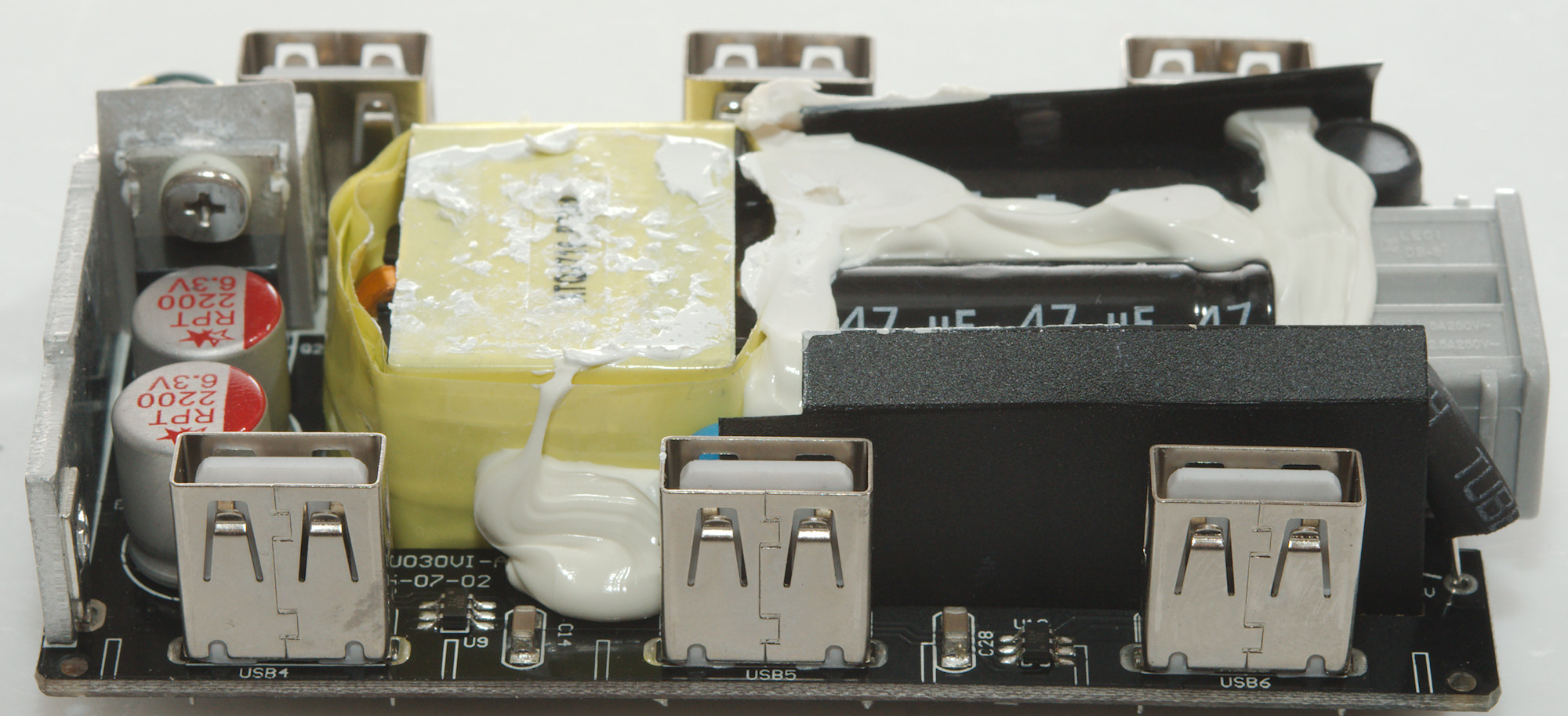
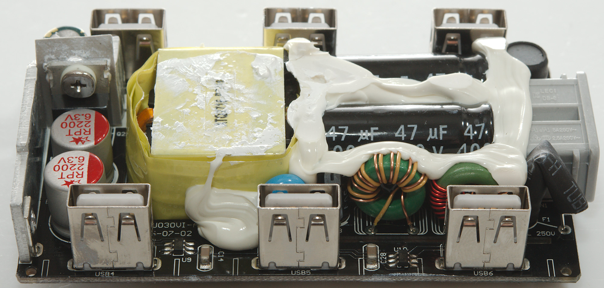
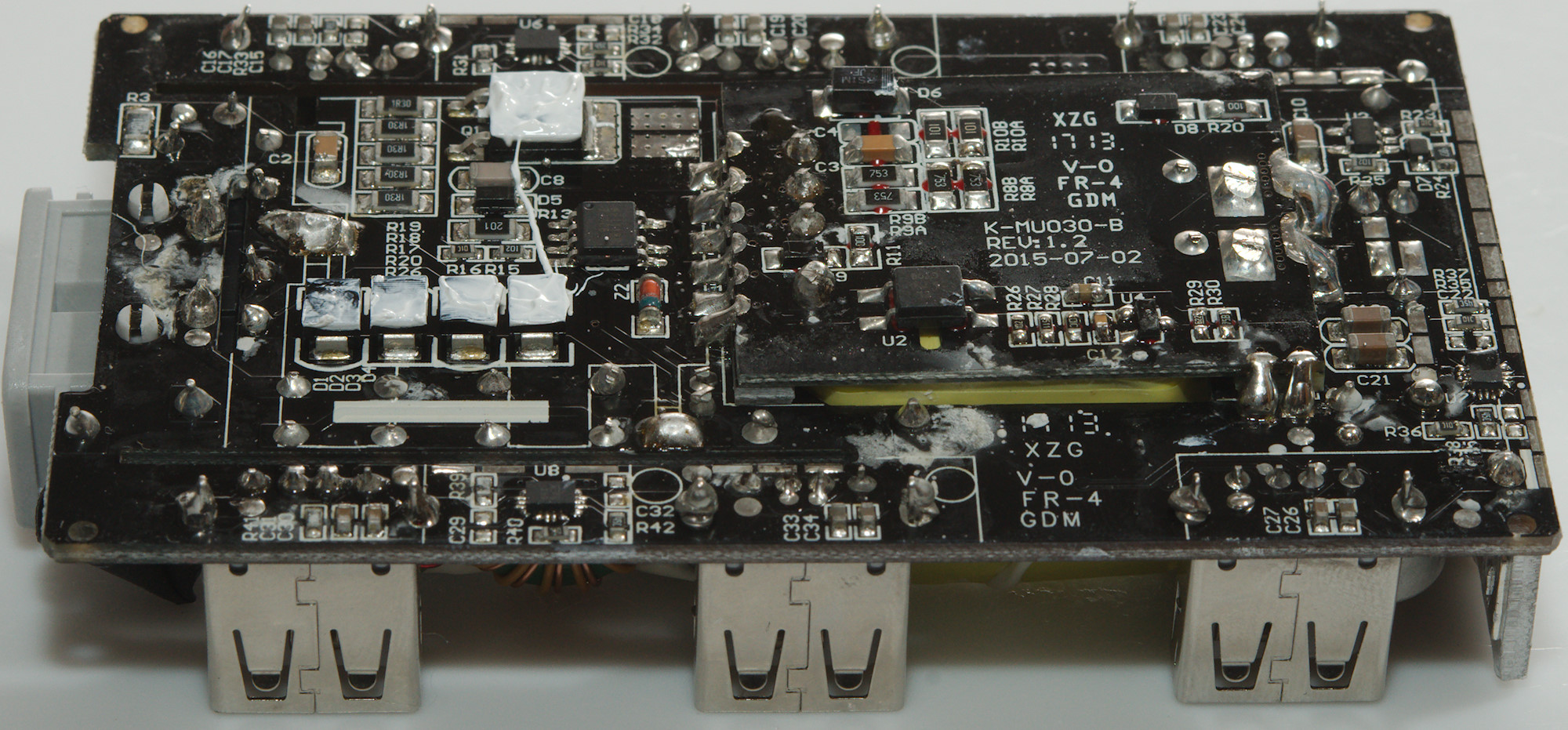
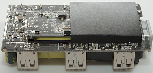
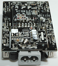
This charger has a fairly complicated build, on this side is A fuse and inductor at the mains input, the blue safety capacitor, 3 auto coding chips (U5, U9, U10: UC2634), a transistor for synchronous rectification (Q2) with a heatsink on.
It looks like the output winding on the transformer is done with flat copper wire.

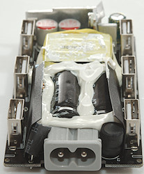
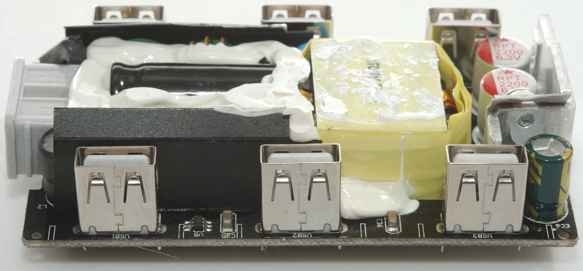
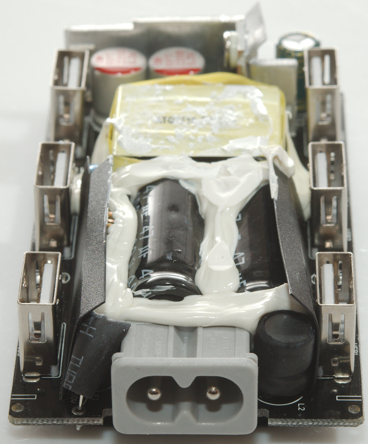
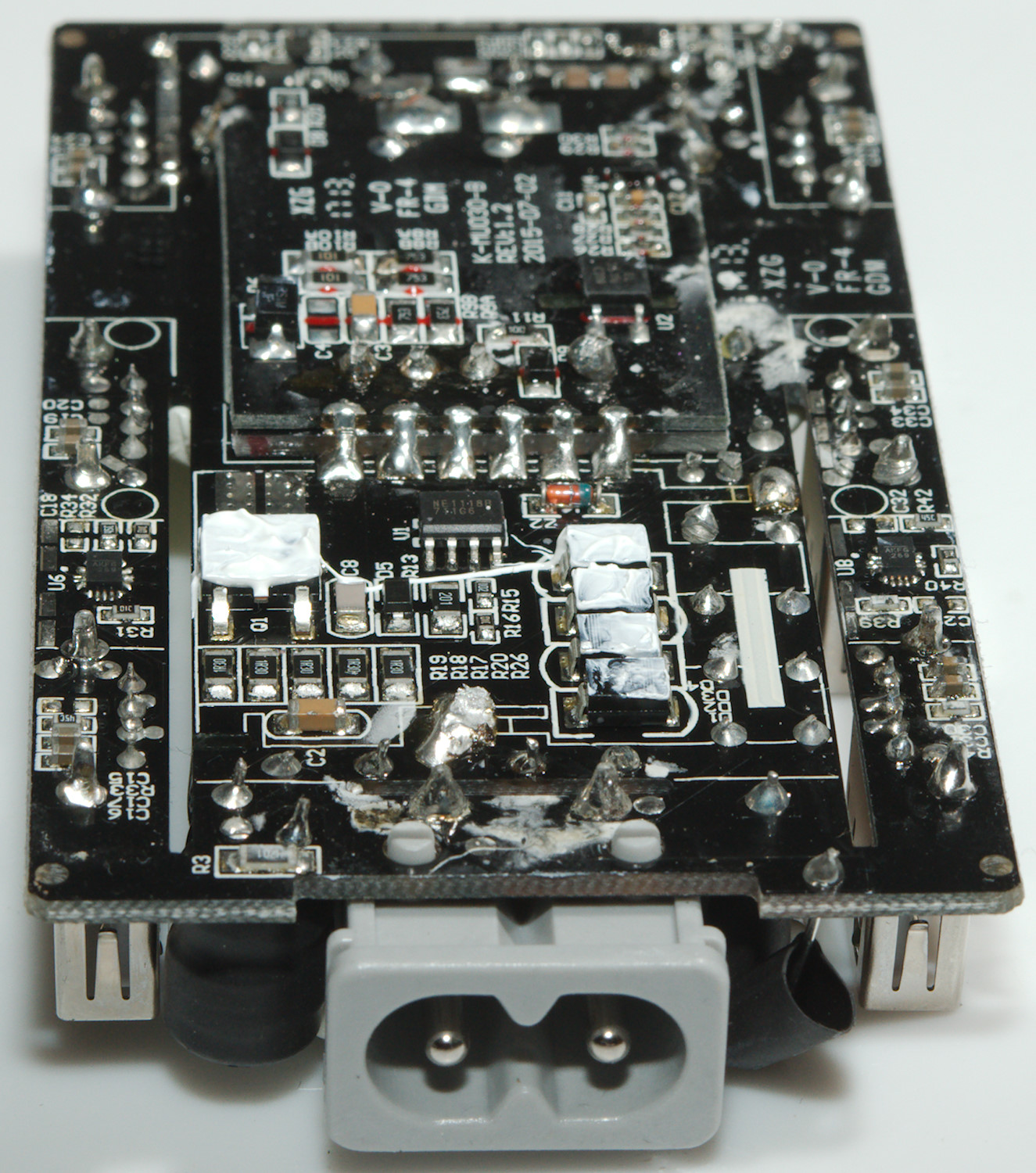
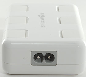
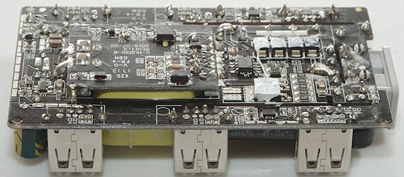
Here the heatshrink covered fuse and input inductor can be seen beside the mains socket.
There is some black isolation paper/plastic around the mains section of the charger.
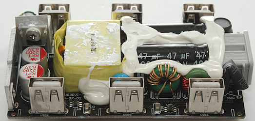
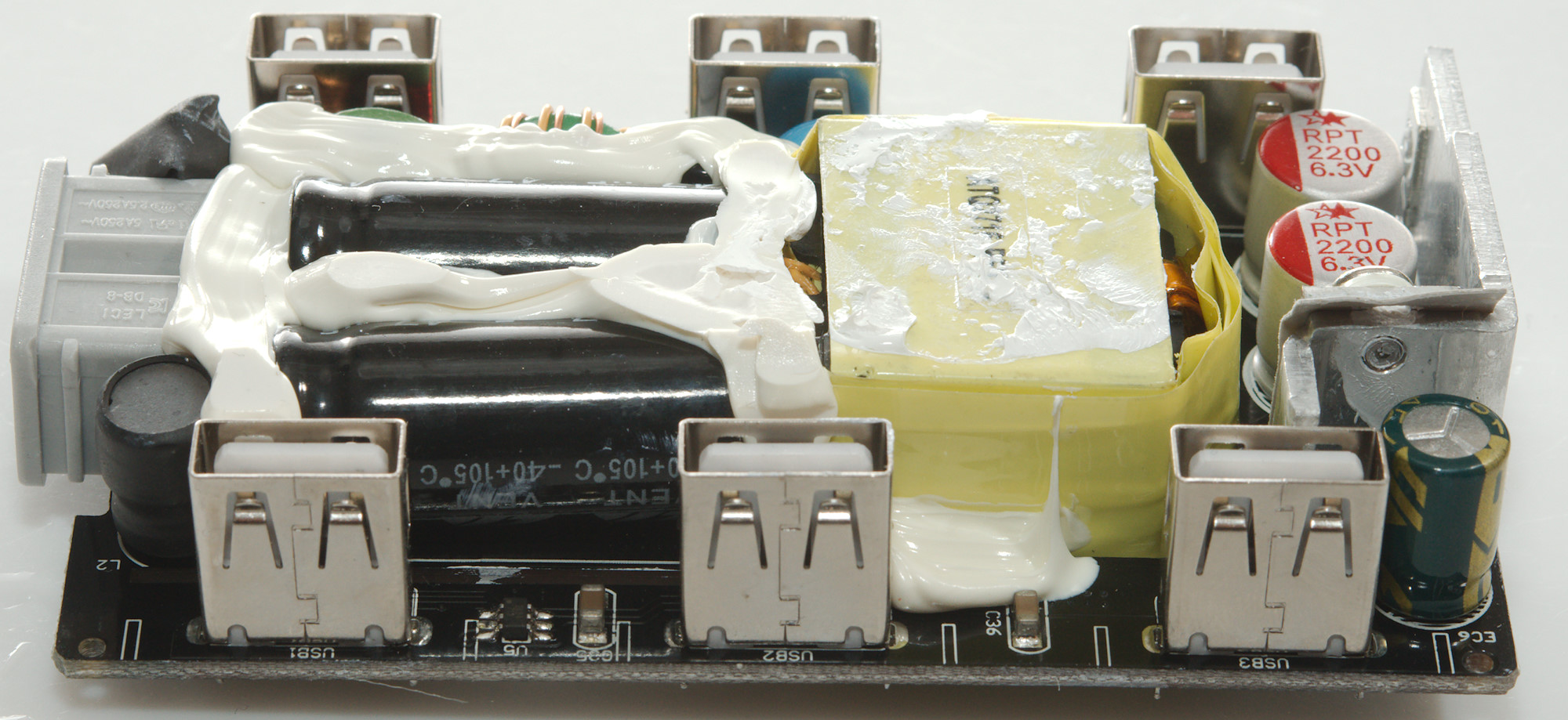
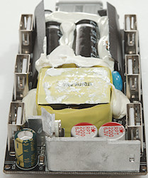
Removing the isolation reveals two common mode coils.
And nothing on this side.
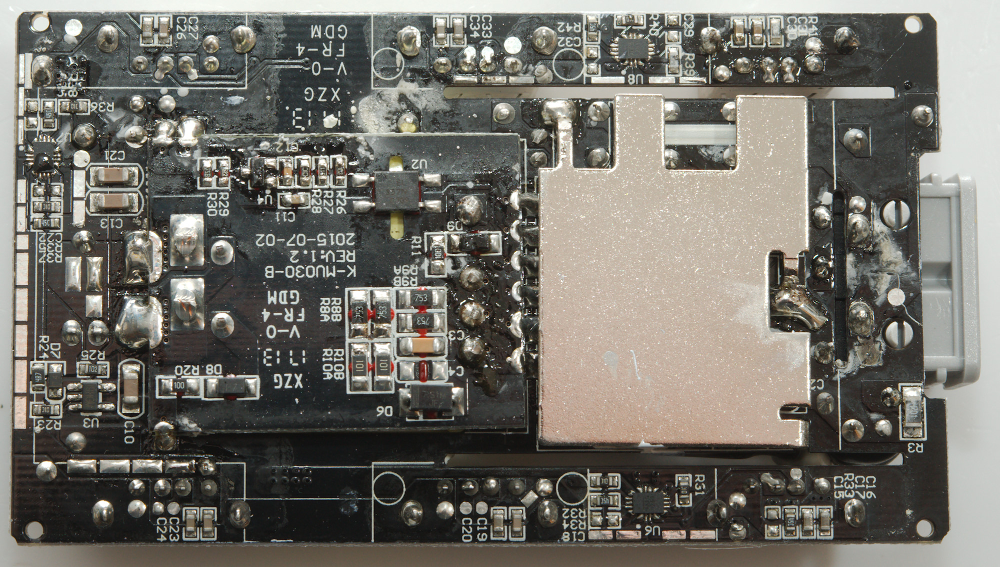
The isolation do also cover the bottom.
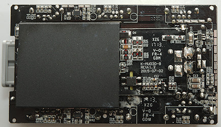
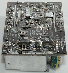
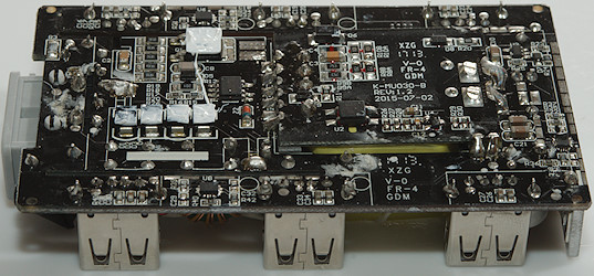
And the bottom of the circuit board is on two levels, the transformer is its own circuit board to get the top low enough for the usb connector.

There is a metal shield below the black isolation, it is soldered at two location..
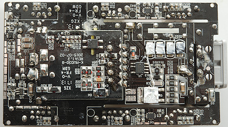
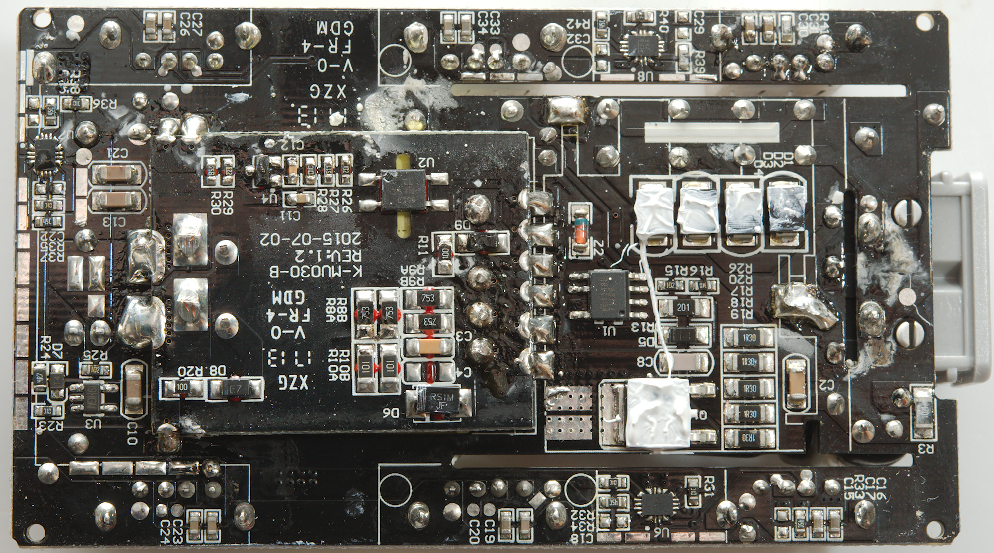
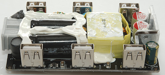
Removing the metal shield shows that it is a heatsink for 4 diodes in a bridge and the mains switcher transistor, the switcher controller is also here (U1: N1118B). The current measurement resistor is 4x 1.3 ohm resistors in parallel (R17, R18, R19, R20, R26: 1R30). The rest of the mains switcher is on the transformer circuit board with a opto feedback and a reference (U4) and the snubber network.
On the low volt side there is a synchronous rectification controller (U3), 3 dual current limiting IC (U6, U7, U8: marked AKFG269).
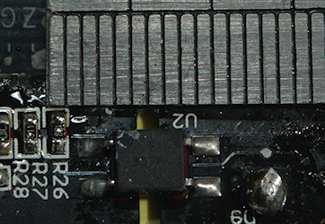
With a slot in the circuit board only 4mm isolation distance is needed and it is present.
Conclusion
This charger has lots of power, individual port protection, auto coding, low noise and good safety. With 10A total output it may not be able to charger 6 very power hungry tablets at a time, but a mix of devices will work fine.
It is a good usb charger.
Notes
Index of all tested USB power supplies/chargers
Read more about how I test USB power supplies/charger
How does a usb charger work?