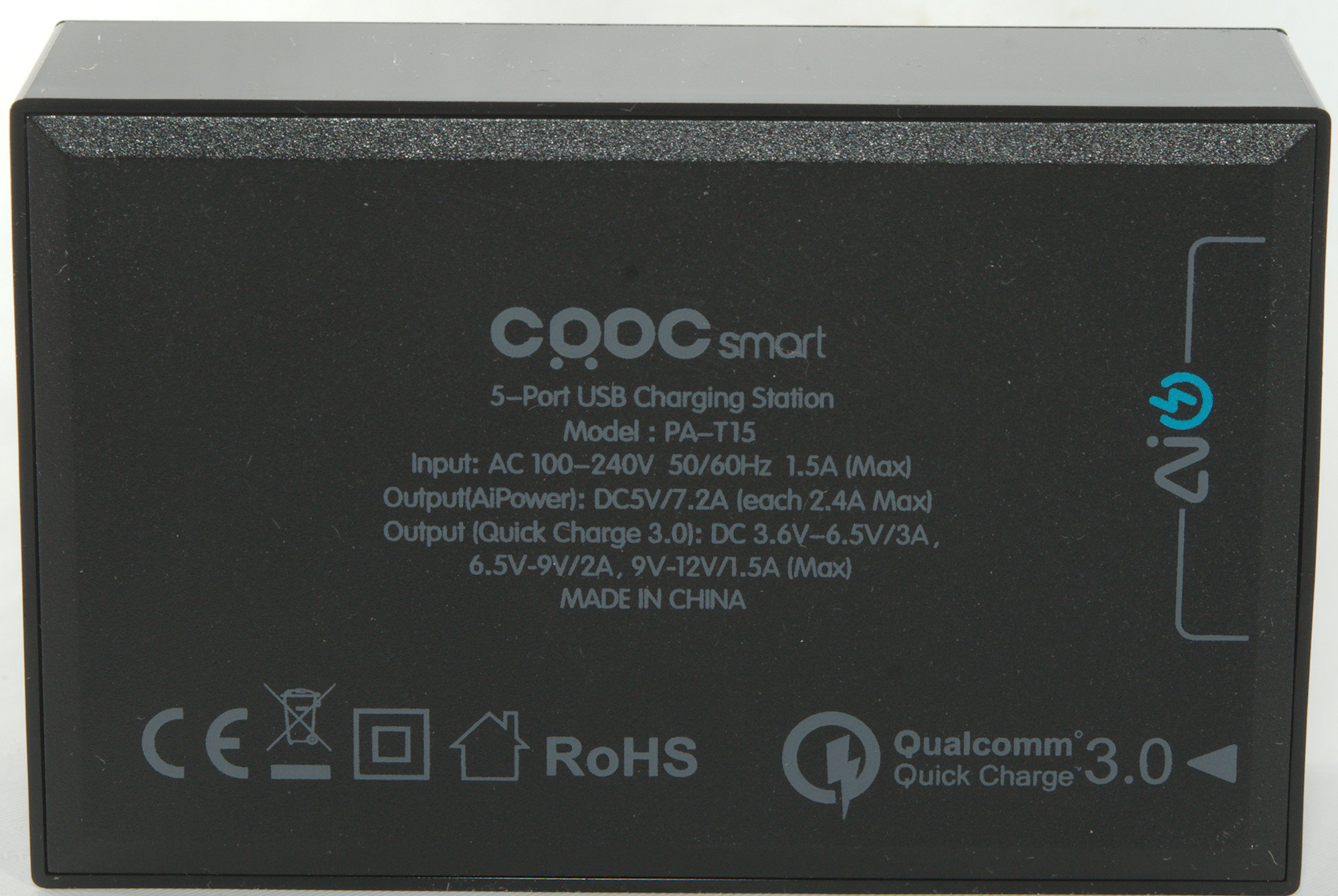
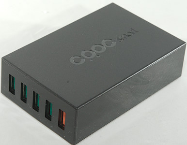
CRDC 5 port QC charger PA-T15
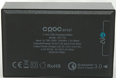
Official specifications:
- Brand Name: CRDC
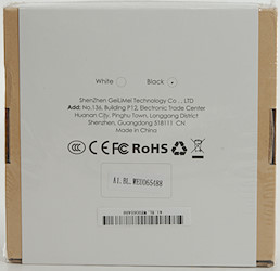
- Quality Certification: RoHS,CE,FCC
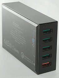
- USB Ports: 5
- Output: 3.6V-6.5V/3A
- Support Quick Charge Technology: Qualcomm Quick Charge 3.0,No
- Output Interface: USB
- Input: 100-240V/0.15A
- Power Source: A.C. Source
It is from Aliexpress dealer: CRDC official store
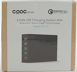
I got it in a card board box.
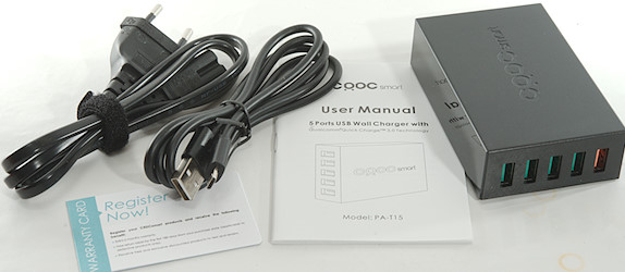
The box contained the charger, mains cable, a usb cable and a manual in multiple languages.
Measurements
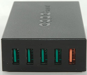
- QC output is auto coding with DCP, Samsung, Apple 2.4A in addition to QC3
- Other usb outputs are auto coding with DCP, Samsung, Apple 2.4A
- Power consumption when idle is 0.3 watt
- All usb outputs has individual overload protection.
- All usb output shares minus.
- Minimum QC3 output is 3.9V
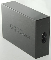
- Weight: 155g without accessories.
- Size: 94 x 60.6 x 26.3mm
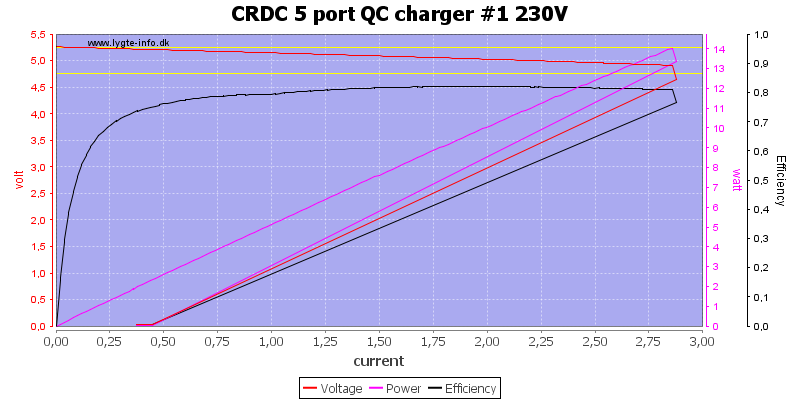
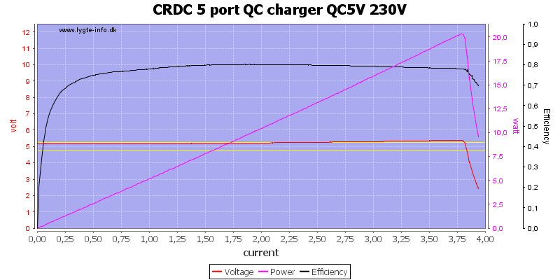
Usb output can deliver about 2.8A before the overload protection trips.

It is the same on another port.
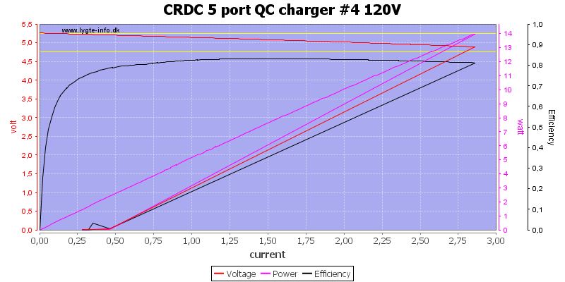
And on 120VAC
The QC output can deliver a bit more, it first trips at about 3.8A
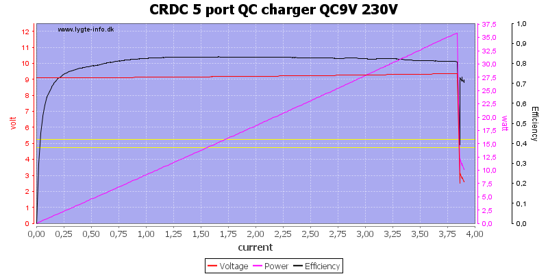
Also at 9V
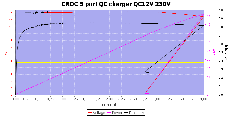
Even at 12V, but here the output starts dropping at 3A
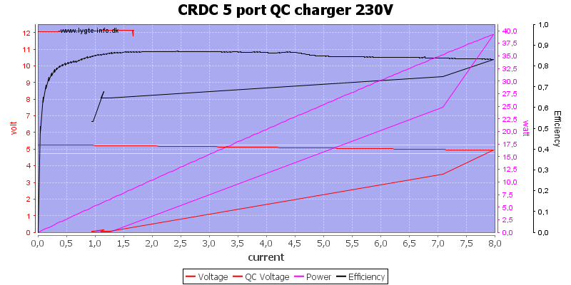
In this load sweep I test with different currents on QC and normal usb output, as can be seen I got 8A on normal output and about 1.6A on QC output before the overload tripped.
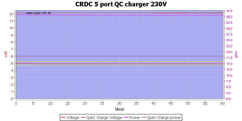
Testing for one hour with rated current: 7.2A at 5V and 1.5A at 12V.
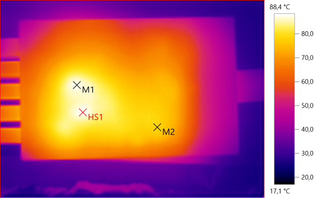
The temperature photos below are taken between 30 minutes and 60 minutes into the one hour test.
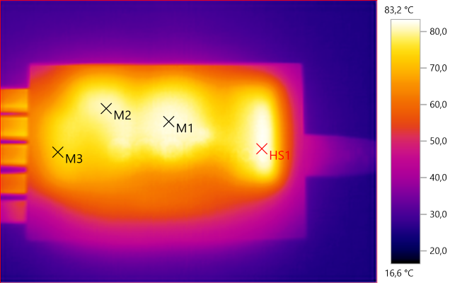
M1: 82.1°C, M2: 80.8°C, M3: 73.5°C, HS1: 83.2°C
HS1 is the mains switcher heatsink, M1 is the transformer and M2/M3 is the rectifier heatsink
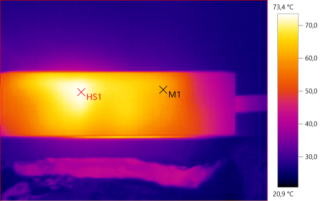
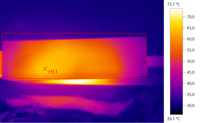
M1: 61.5°C, HS1: 73.4°C
M1: 87.5°C, M2: 78.2°C, HS1: 88.4°C
HS1 & M1 is from the rectifier heatsink.
HS1: 65.6°C
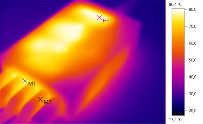
M1: 76.9°C, M2: 59.8°C, HS1: 80.4°C
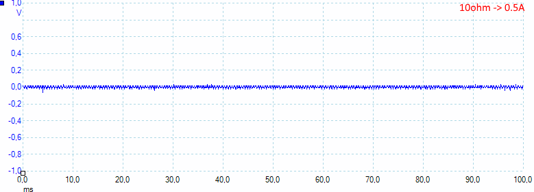
At 0.5A output the noise is 11mV rms and 154mVpp.
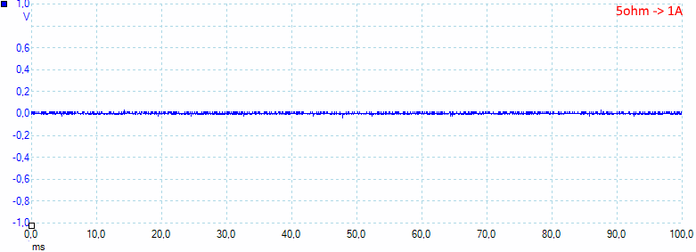
At 1A the noise is 14mV rms and 203mVpp.
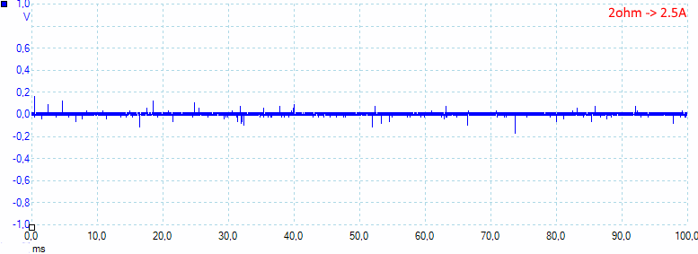
At 2.5A the noise is 23mV rms and 88mVpp.
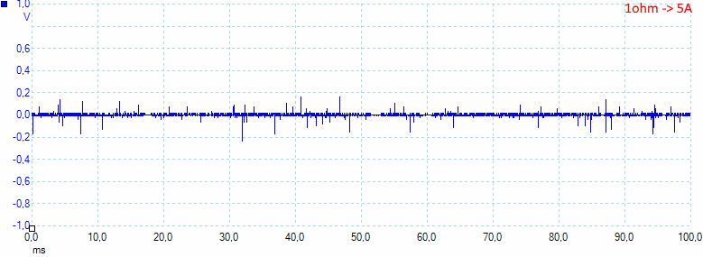
At 5A the noise is 35mV rms and 556mVpp.

On QuickCharger at 0.5A the noise is 10mV rms and 407mVpp.
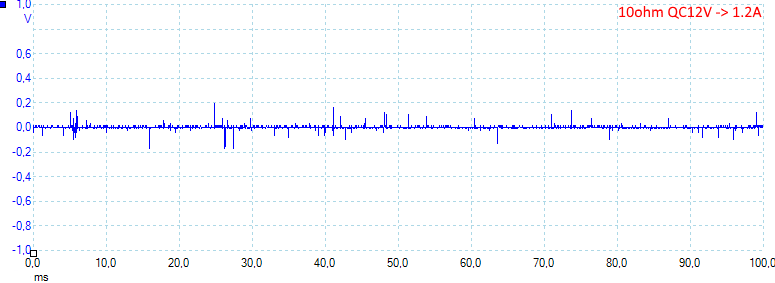
At 12V 1.2A the noise is 13mV rms and 502mVpp.
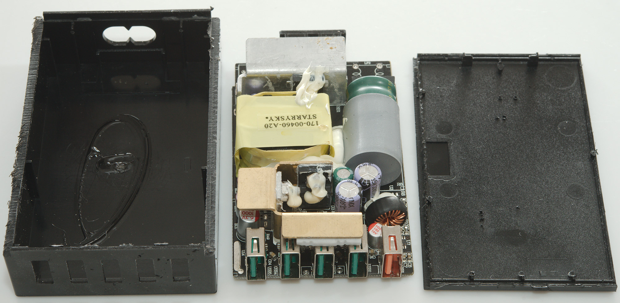
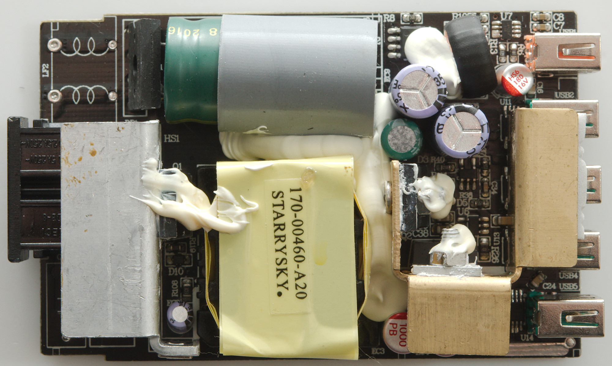
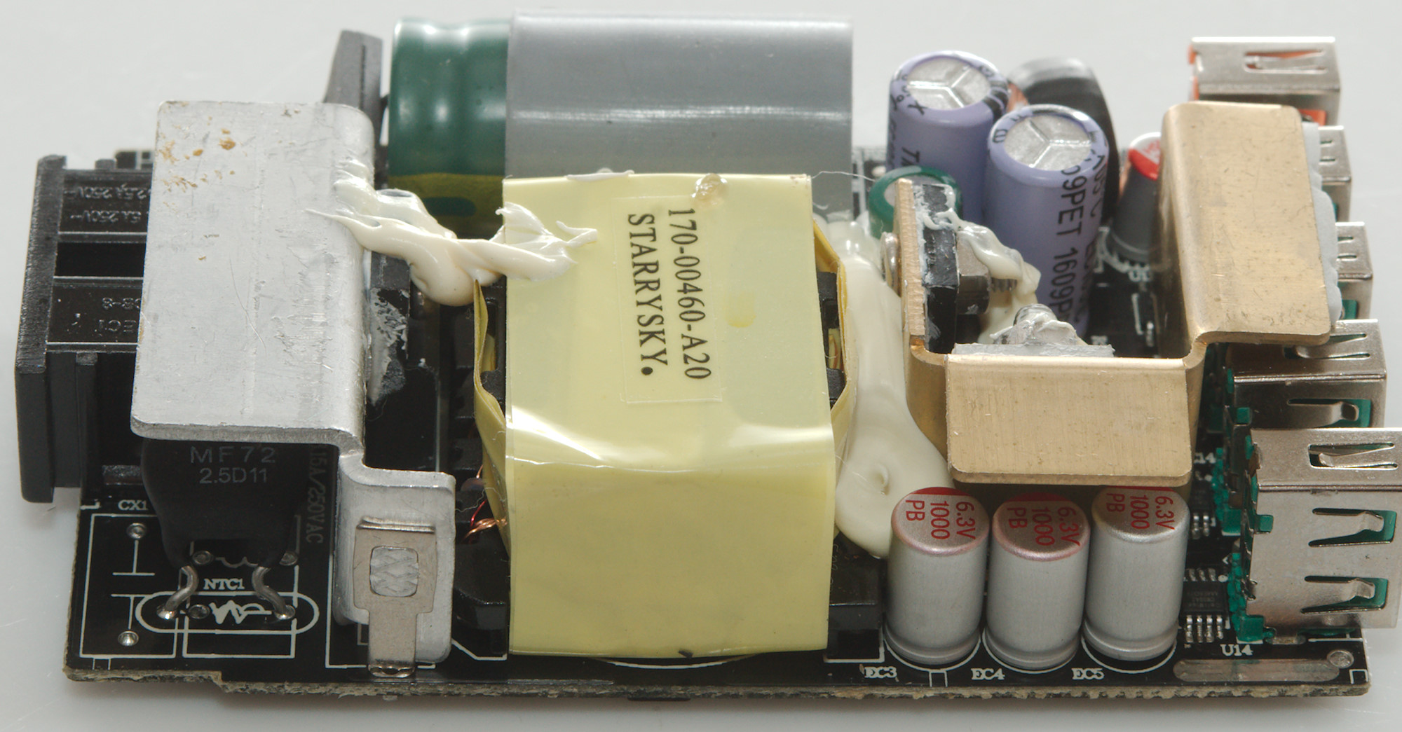
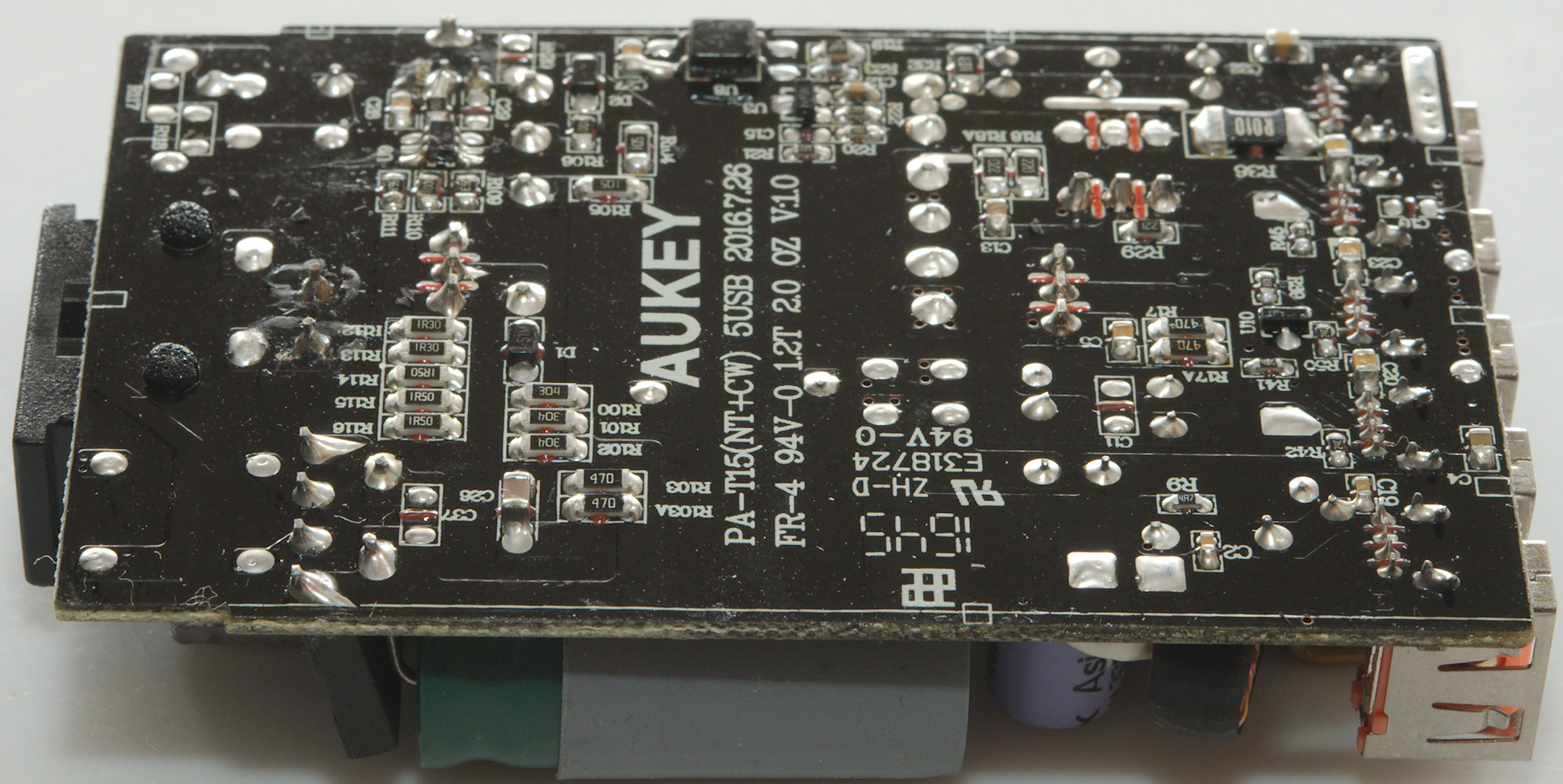
Tear down
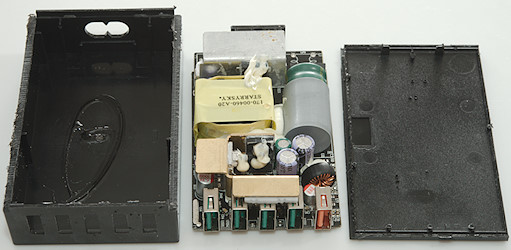
The glue worked on this one, I could not open it with my vice and had to cut.

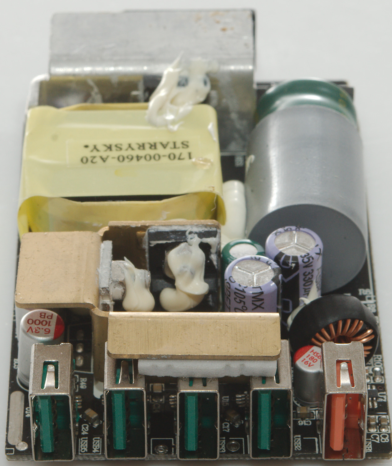
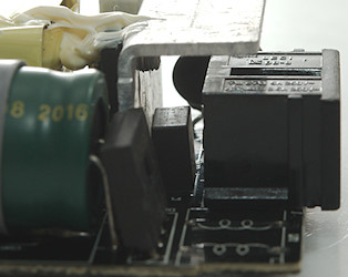
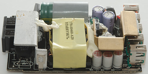
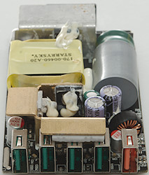
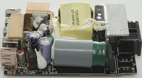
It is very obvious that the common mode coil is missing on this. There is a bridge rectifier next to the large smoothing capacitor that has a rubber boot on to get better isolation to the low volt side (Very good). On the heatsink next to the mains input is the switcher transistor (Q1).
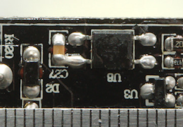
On the low volt side there is a diode (D3) and a transistor (Q2) on the heatsink. Diode is rectifier for QuickCharge and transistor a synchronous rectifier for the other outputs with the help of a chip (U6 marked 19HGF), there is also another chip (U12 marked A63A). The QC circuit is a switcher (U2: Hidden below the white stuff next to the inductor) and a QC controller (U7 marked pgz682).
Behind each of the ordinary usb ports is a auto coding and current limiting chip (U11, U12, U13, U14: CellWise CW3042).
The QC switcher has a input voltage of 13.8V
I did not see any safety capacitor, but according to the solder pads something is placed between the transformer and the large capacitor and because it is between mains a low volt side it must be a safety capacitor.
Below the mains switcher heatsink is a fuse and a inrush current limiter (NTC).
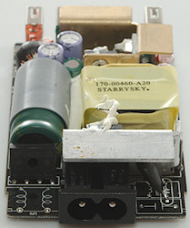
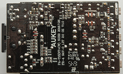
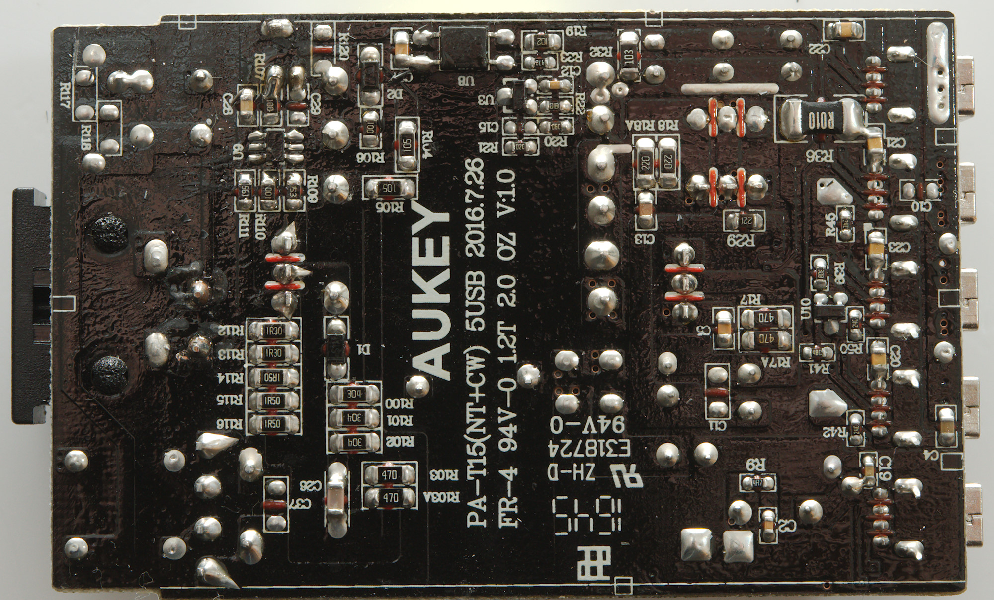
There is not many chips on this side, but the mains switcher controller is here (U9) and the opto feedback (U8) together with the reference (U3: probably a 431). The is a small chip more on the low volt side U10), there is also a low ohmic resistor (R36 0.01ohm). A guess could be that the resistor together with U10 & U12 is a overall current limit.
The current measurement for the mains switcher transistor is 5 resistors in parallel (R112..R116: 1.3 & 1.5ohm). The snubber netwrok has 3 resistors in parallel (R100..R102: 3x300kohm).
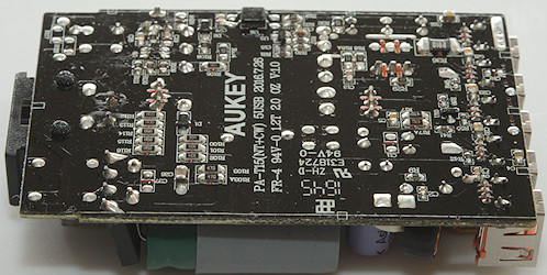
The isolation distance looks fine.
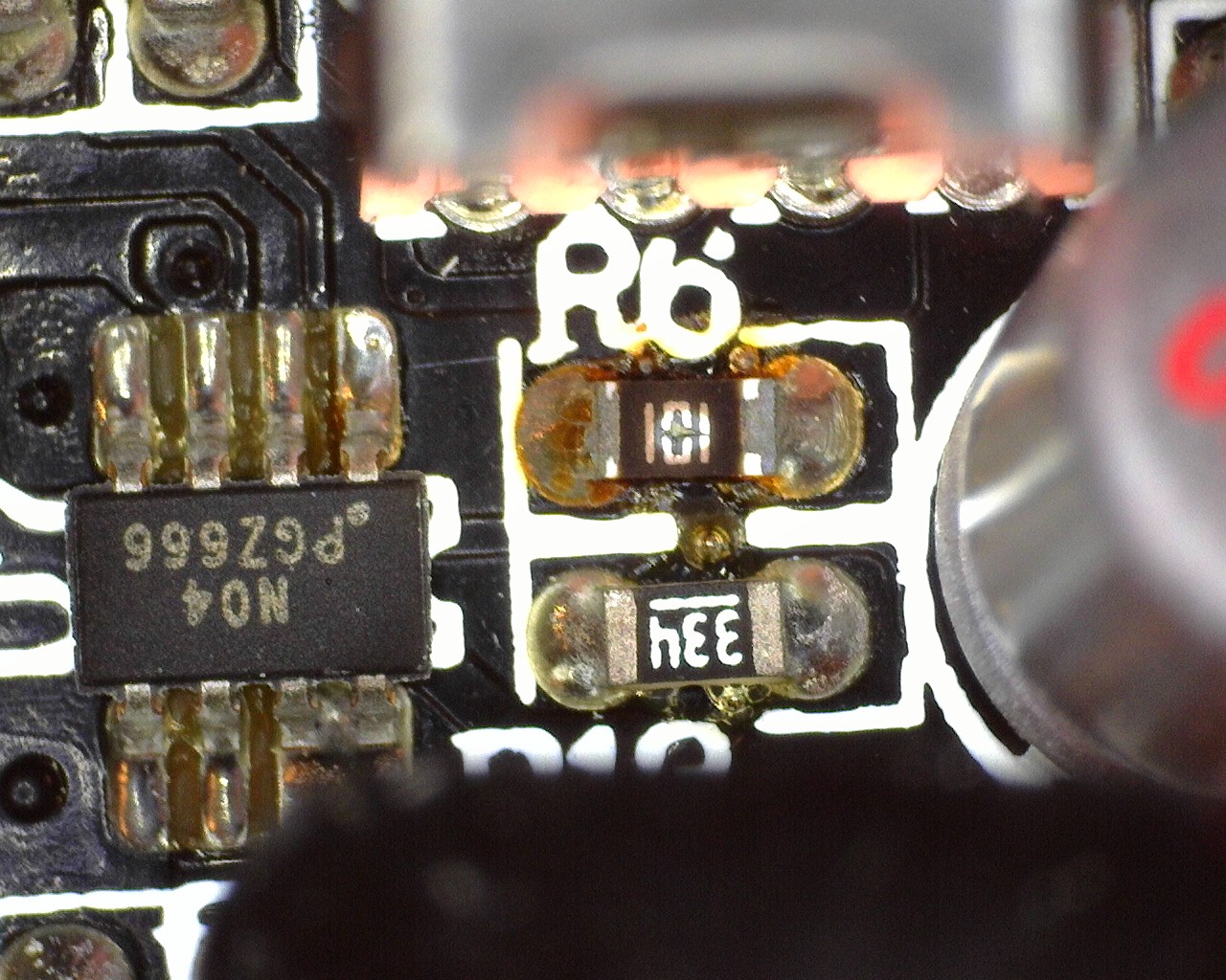
A sad story
One of my readers had contacted me about this charger, it had fried some equipment on the QC port. He sent it to me and a check showed that there was over 12V on the QC port, without any device connected. I.e. anything plugged into it would get 12V, not very healthy for usb devices.
I opened it up (This time without cutting).
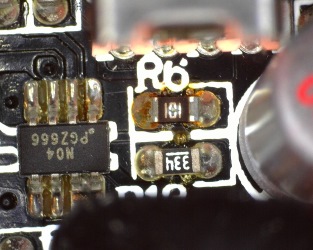
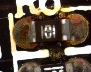
Here is the area that handles QuickCharge. Look at the resistor marked "101" it is damaged, it is probably the reason for the problem. It is also interesrting that this chip has another number than the one in the charger I tested.
I cannot say why this happened, some possibilities are: Faulty chip, faulty soldering, a zap from a finger/device on the usb port.
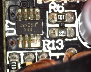
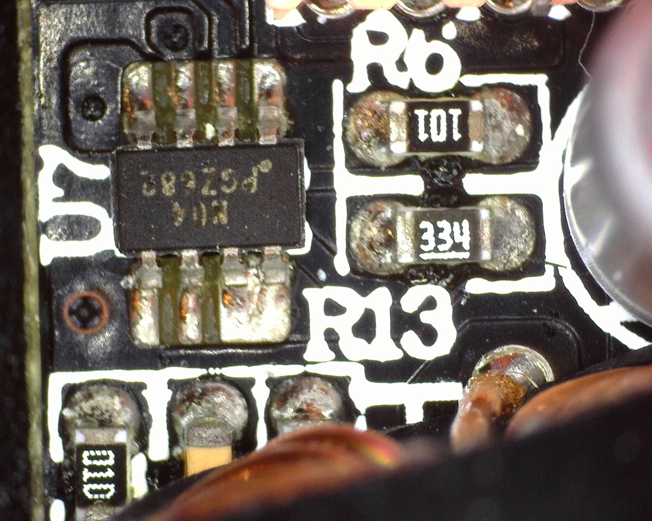
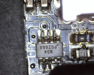
Same area from the charger I tested.
I found one other chip that was different: 19HFN instead of 19HGF
Testing with 2830 volt and 4242 volt between mains and low volt side, did not show any safety problems.
Conclusion
Five outputs each can deliver 2.4A (if all is used at the same time the limit is more like 2A for each output when used simultaneously), all with automatic coding and one with QC3. The noise is acceptable and very low at lower load, the individual port protection makes it a bit more safe and it did not have any safety issues with the mains. It do get fairly warm at full load.
I will call it a good charger.
Notes
They say they are the same as Aukey, but the equivalent model from Aukey has a small difference in the QuickCharge circuit, this one is a bit better (This may be due to different versions of the same charger).
Index of all tested USB power supplies/chargers
Read more about how I test USB power supplies/charger
How does a usb charger work?