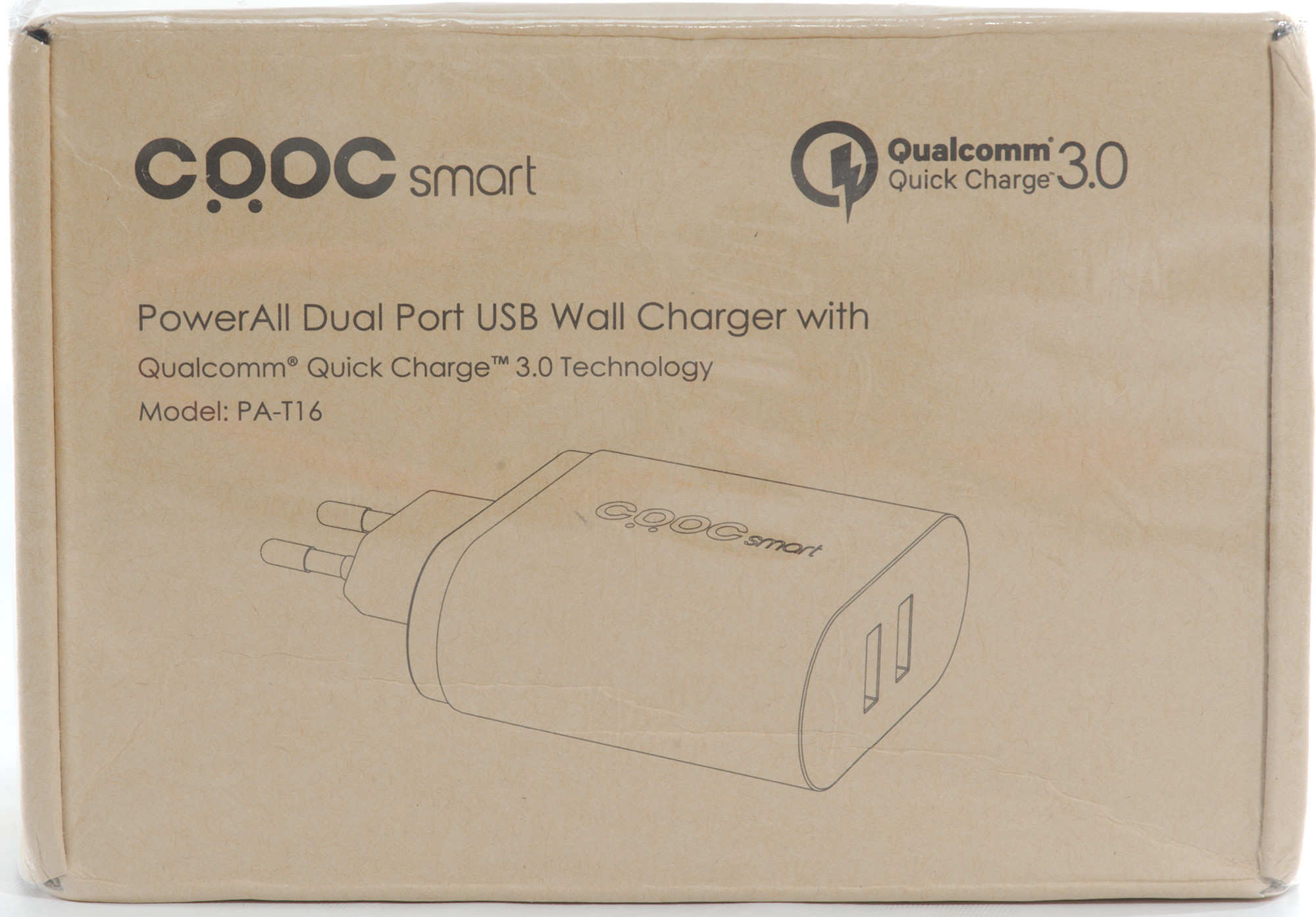
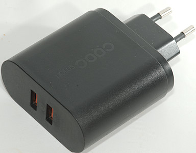
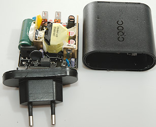
CRDC Dual QC3 charger PA-T16
Official specifications:
- All Ports are Intelligent Max Output and Max Speed According to Your Devices Can Accept.
- Tech: Qualcomme Quick Charge 3.0 & AiPower Smart Adaptive Charging;
- Output 1(Quick Charge 3.0): 3.6-6.5V/3A 6.5V-9V/2A 9V-12V/1.5A
- Output 2(Quick Charge 3.0): 3.6-6.5V/3A 6.5V-9V/2A 9V-12V/1.5A
- Dimensions: 6.4*6.3*2.8 cm/2.52*2.48*1.10 inch (L*W*H)
- Weight: 116g/4.09oz
- Input:AC 100-240V 50-60HZ 1.2A (Max)
I got it from a Aliexpress dealer: Energi run Store
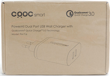
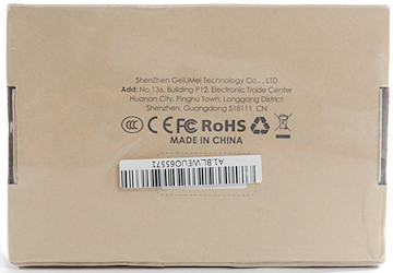
I got it in a brown cardboard box with a little bit of information on it.
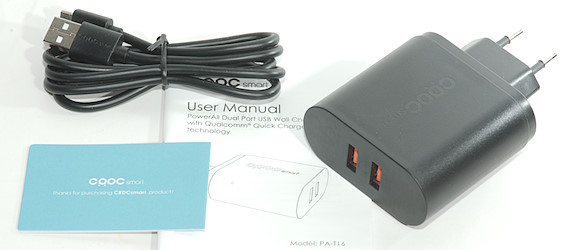
It contained the charger, a usb cable and a instruction sheet.
Measurements
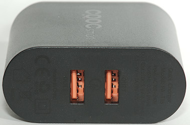
- Outputs is QC3 with auto coding
- Power consumption when idle is 0.45 watt
- Minimum QC3 voltage is 3.8 volt.
- The two outputs has a common ground.
- Weight: 116g
- Size: 100.5 x 64 x 28.2mm
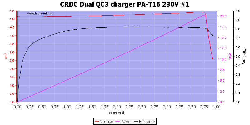
The charger can deliver about 3.7A before overload protection kicks in and it will increase output voltage slightly with load to compensate for cable drop (nice).
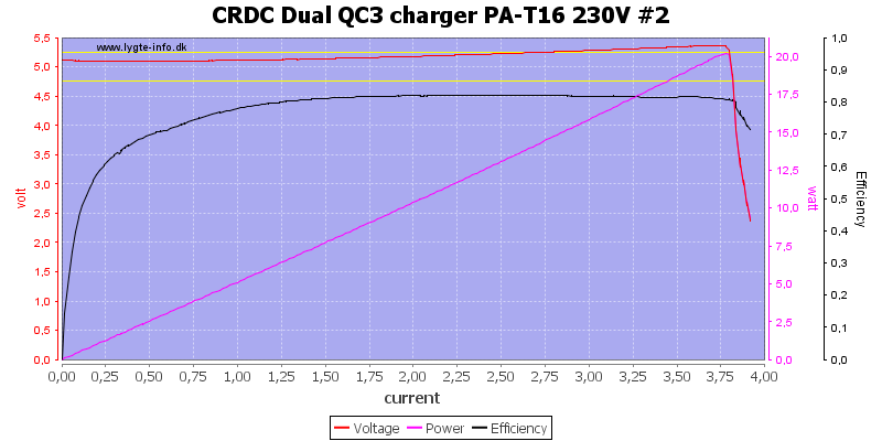
The second output looks the same.
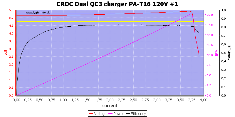
Using 102VAC do not change anything.
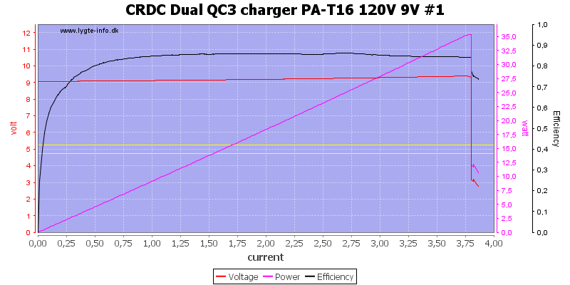
At 9V output it can also deliver 3.7A
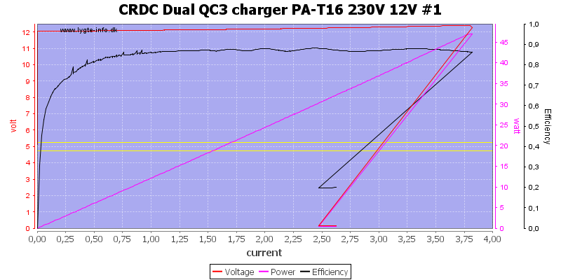
Even at 12V it can deliver 3.7A.
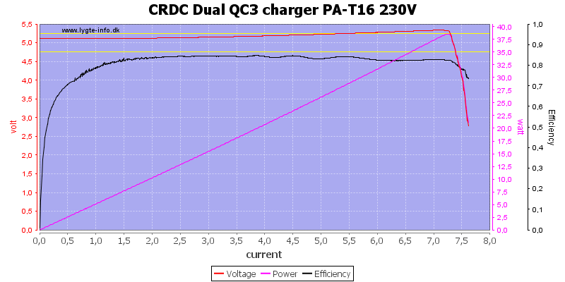
Both output at 5V can deliver more than 7A together.
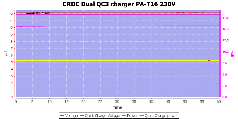
Here I run one output at 5V 3A and the other at 12V 1.5A for one hour, the charge can handle that.
The temperature photos below are taken between 30 minutes and 60 minutes into the one hour test.
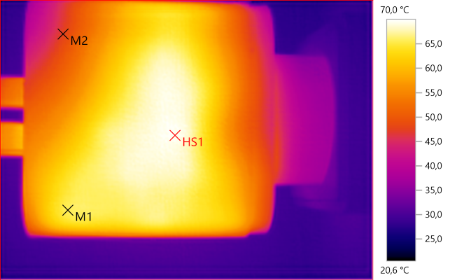
M1: 65,7°C, M2: 47,4°C, HS1: 70,0°C
HS1 is the transformer.
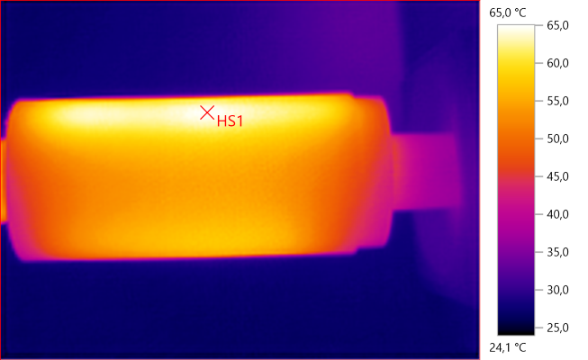
HS1: 65,0°C
HS1 is probably from the rectifier heatsink.
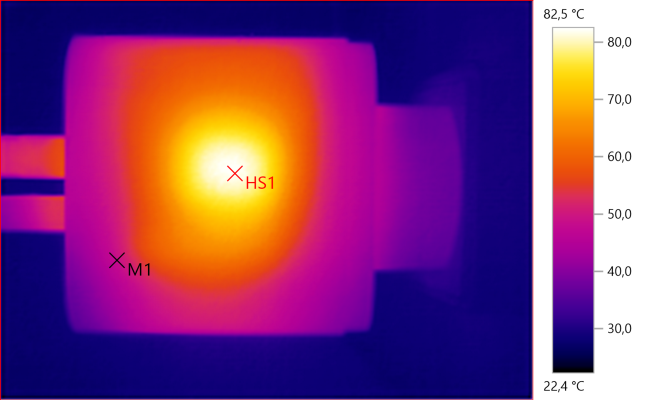
M1: 48,5°C, HS1: 82,5°C
HS1 is from the transformer, probably some of the white stuff touching the box.
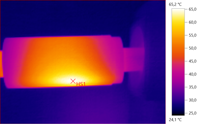
HS1: 65,2°C
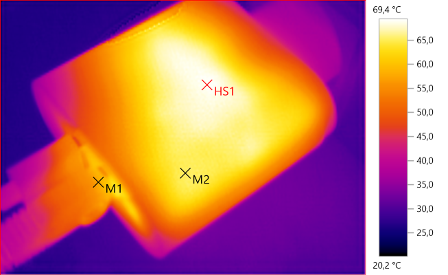
M1: 57,6°C, M2: 65,3°C, HS1: 69,4°C
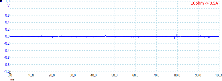
At 0.5A the noise is 9mV rms and 182mVpp
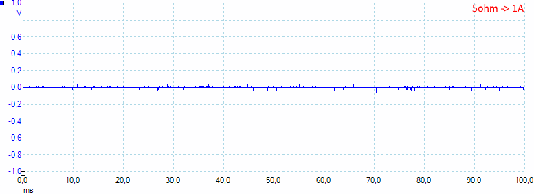
At 1A the noise is 6mV rms and 157mVpp
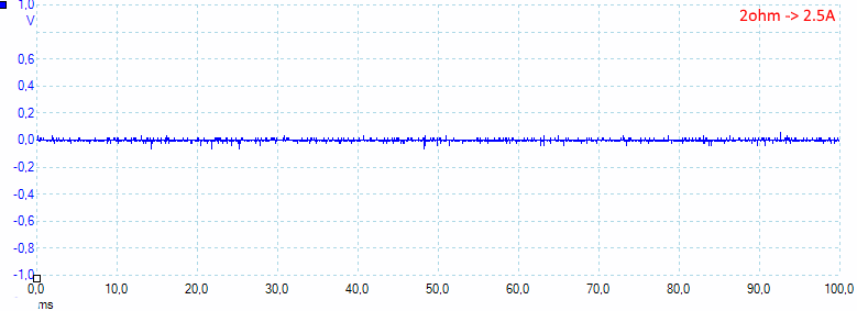
At 2.5A the noise is 31mV rms and 218mVpp.
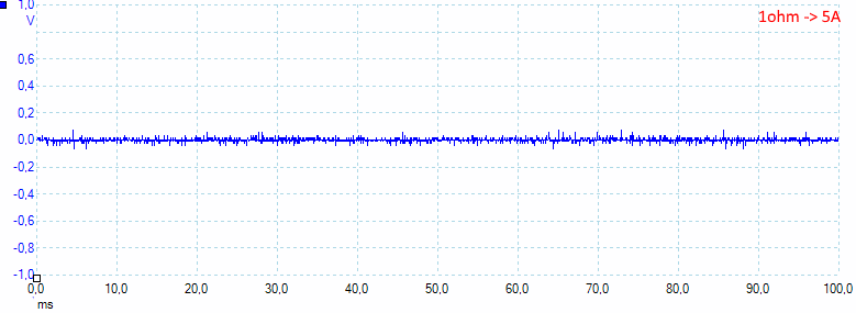
At 5A with both outputs in parallel the noise is 11mV rms and 195mVpp.
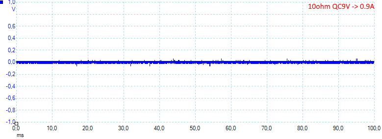
At 0.9A the noise is 18mV rms and 152mVpp.
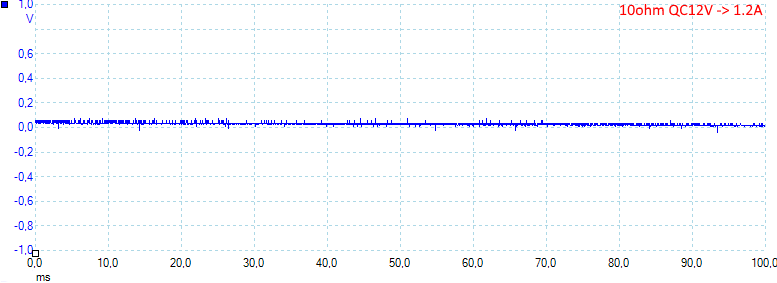
At 1.2A the noise is 5mV rms and 145mVpp, all very low values.
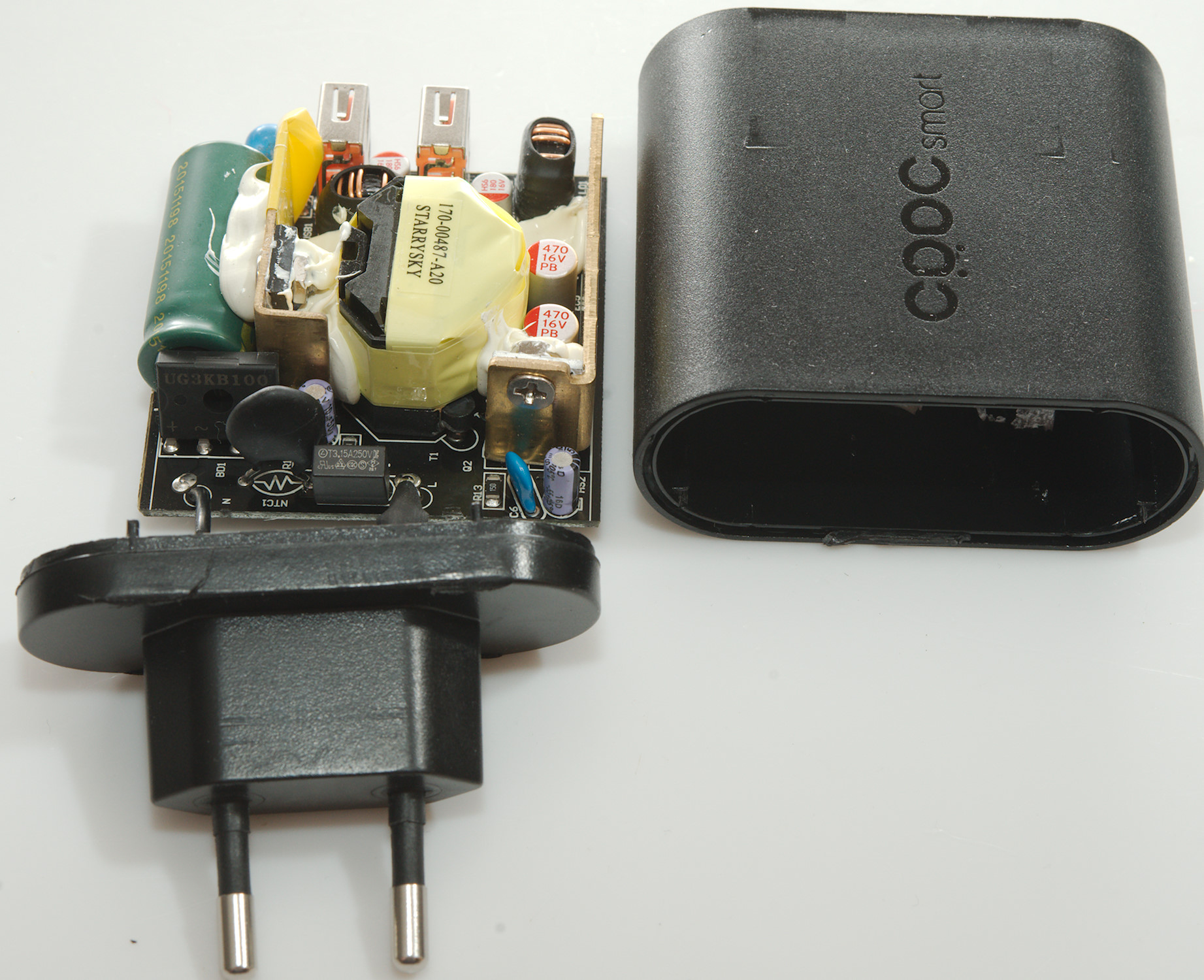
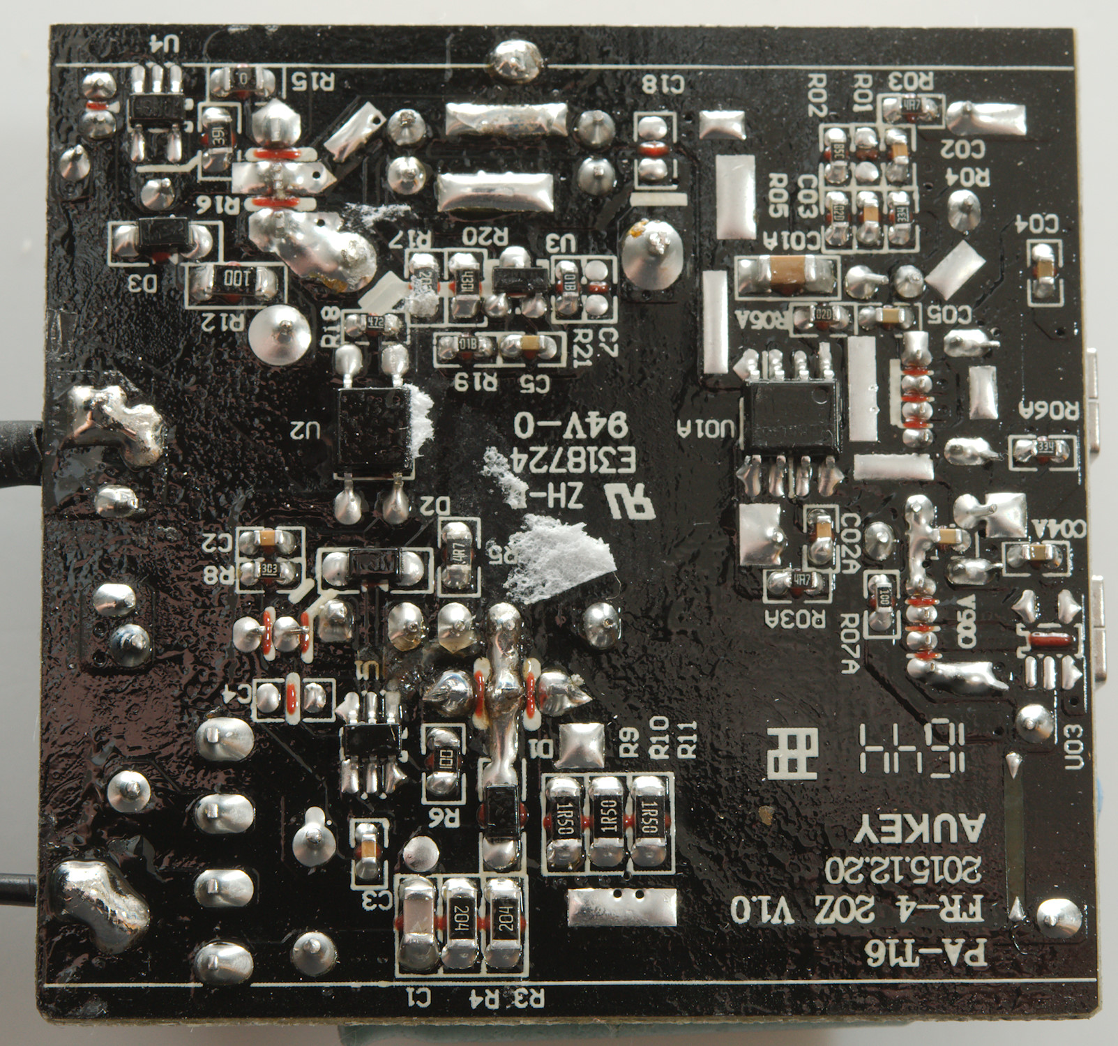
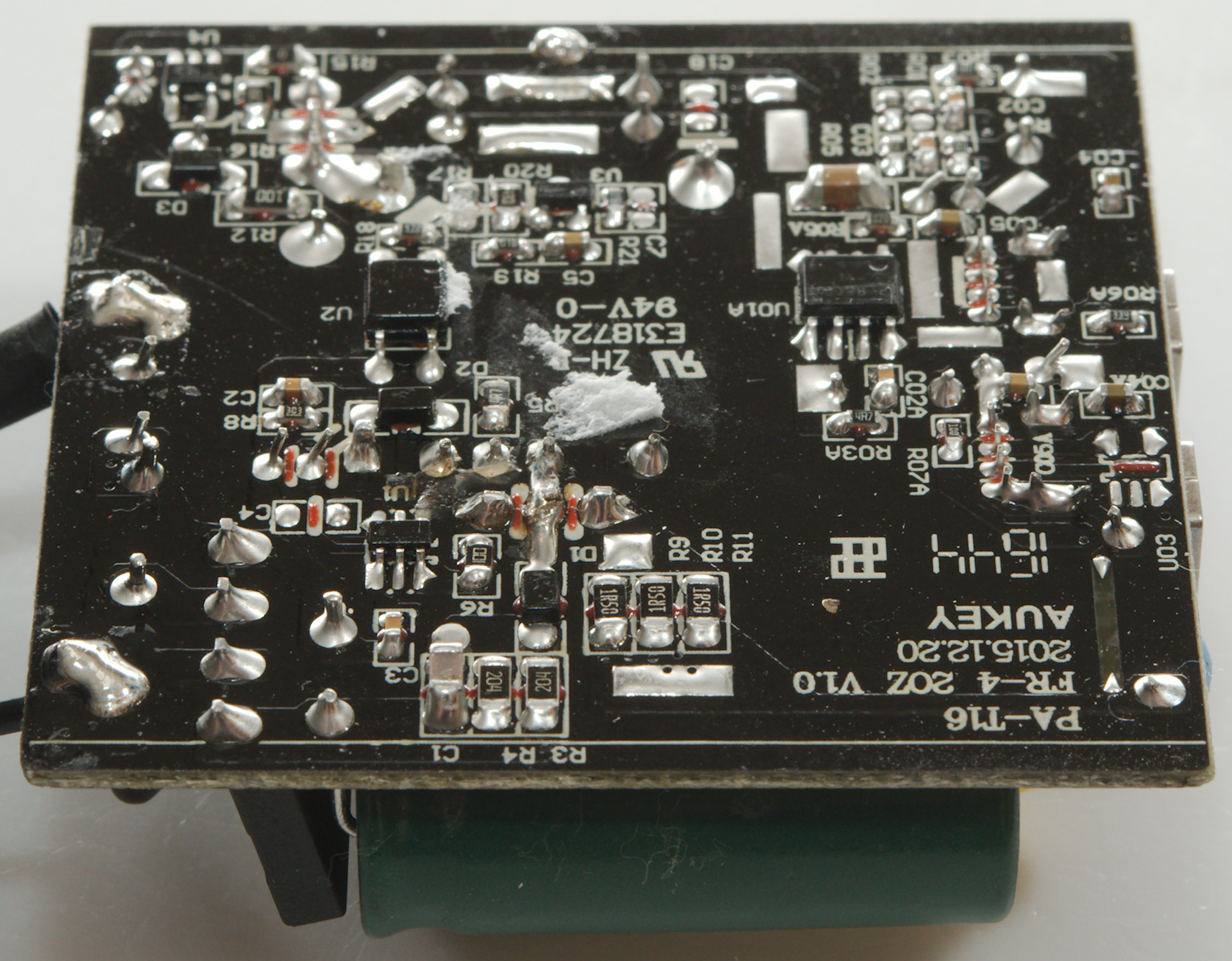
Tear down
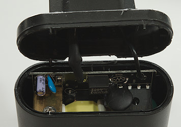
I expected that I could break the tail on this charger with the help of my vice and a mallet. I could but it was harder than expected.
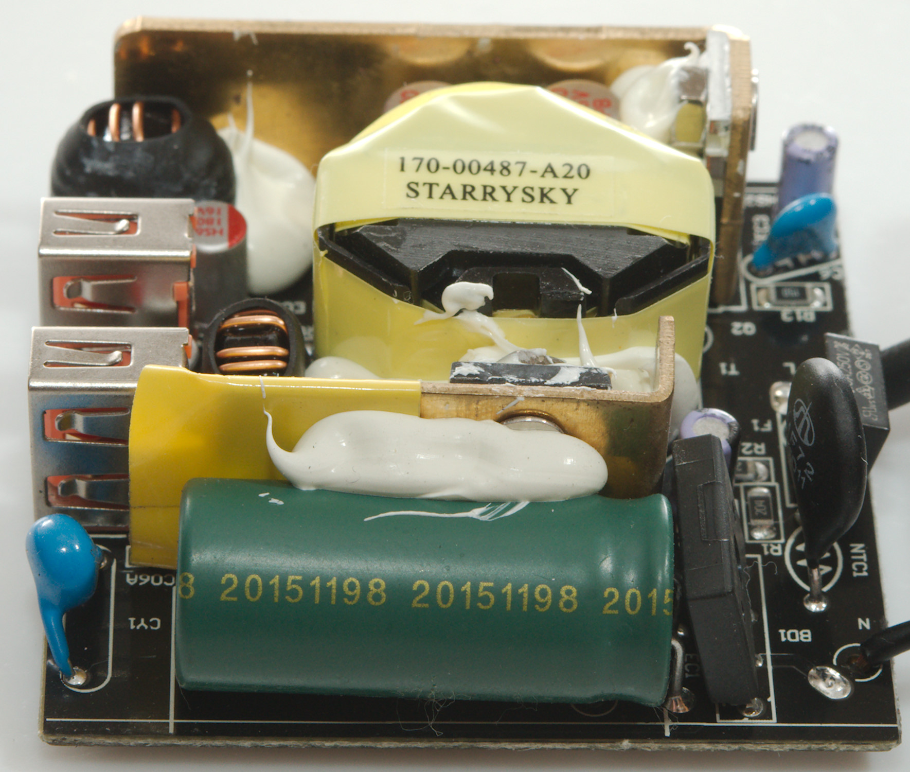
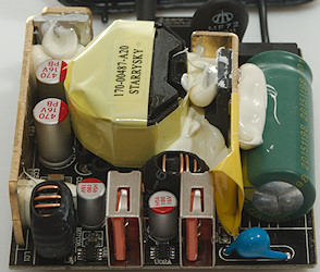
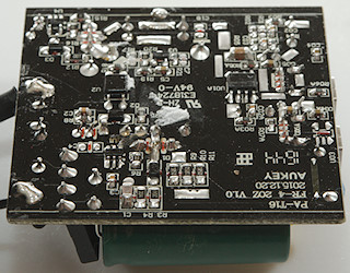
At the mains input is a fuse (F1: 3.15A/250V), a inrush limited (NTC1) and a bridge rectifier (BD1). Close to the big green capacitor is the mains switcher on a small heatsink. There is also a safety capacitor (CY1). At the edge of the circuit board is the heatsink for the rectifier transistor (Q2).
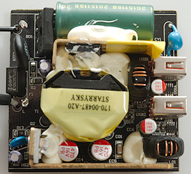
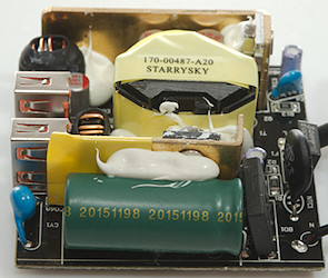
On the low volt side is also two inductor, one for each usb output and two controller chips (U02 & U02A: PGZ684), they are probably complete QC controllers and switchers in a single chip. The internal voltage is 13.2V the two chips then adjust it to 5V, 9V and 12 output.
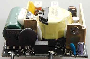
The first picture is the rectifier transistors heatsink. On the second picture is the two control chips and the blue safety capacitor.
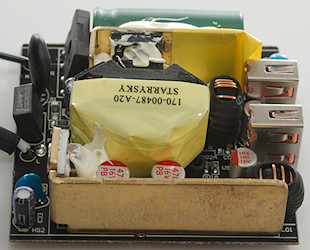
The first picture is the mains capacitor with a safety capacitor at one end and a bridge rectifier at the other end.
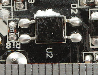
The synchronous rectification controller (U4) is placed next to the rectifier transistor and in this area is also the reference (U3) and the opto coupler (U2).
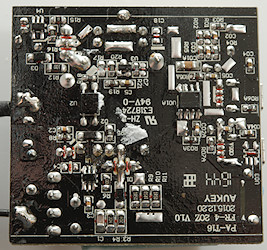
I did not find out what U01A do, with black on black it is difficult to trace the circuit.
The safety distance looks fine here.
Testing with 2830 volt and 4242 volt between mains and low volt side, did not show any safety problems.
Conclusion
A powerful dual port QuickCharge adapter with auto coding for non-QC equipment, low noise, good safety.
This is a good usb power supply.
Notes
Index of all tested USB power supplies/chargers
Read more about how I test USB power supplies/charger
How does a usb charger work?