Chuwi Hi-Charger QC3 A-100
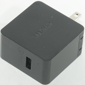
Official specifications:
- Input: 100-240VAC 50/60Hz 0-5A
- Output: 5V/3.0A, 9.0V/2.0A, 12.0V/1.5A
- Gross power: 18W
- Dimensions: 50*50*28mm
- Weight: 65g
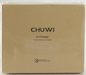
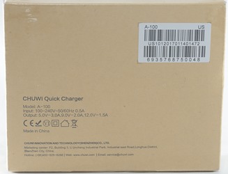


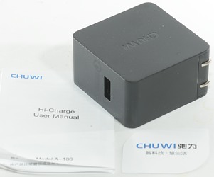
The box contains the charger and a instruction sheet.
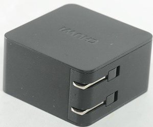
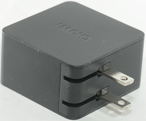
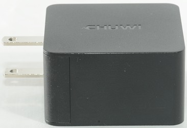
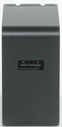
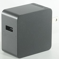
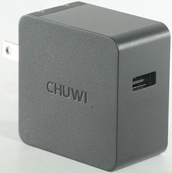
Measurements
- Power consumption when idle is 0.04 watt
- Output coded as Quick Charge v2.0 & v3.0
- Minimum QC3 voltage is 3.3v
- Weight: 62g
- Size: 50 x 50 x 28mm
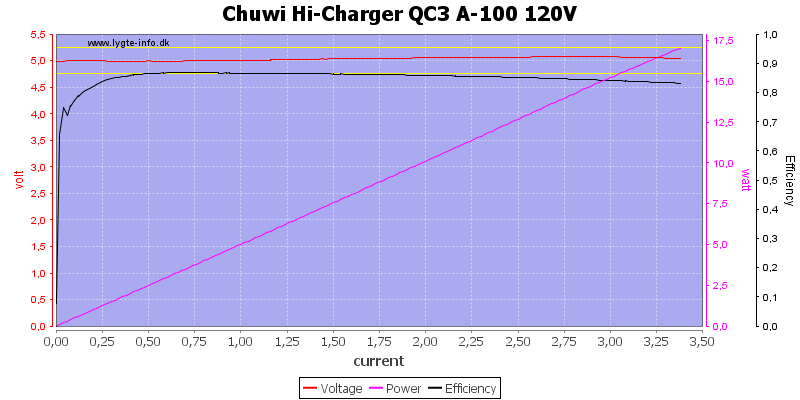
The output is rated 3A and it can deliver about 3.3A, this is very good. The efficiency is also very good.
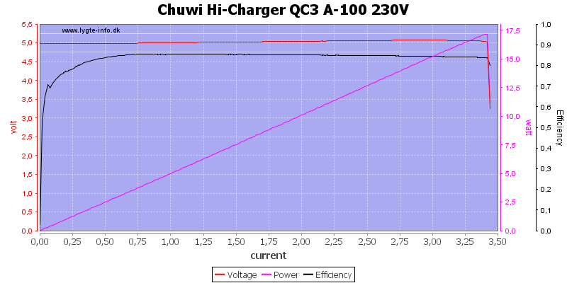
With 230V AC input the maximum output current increases slightly and the efficiency is reduced a bit, but is still very good.
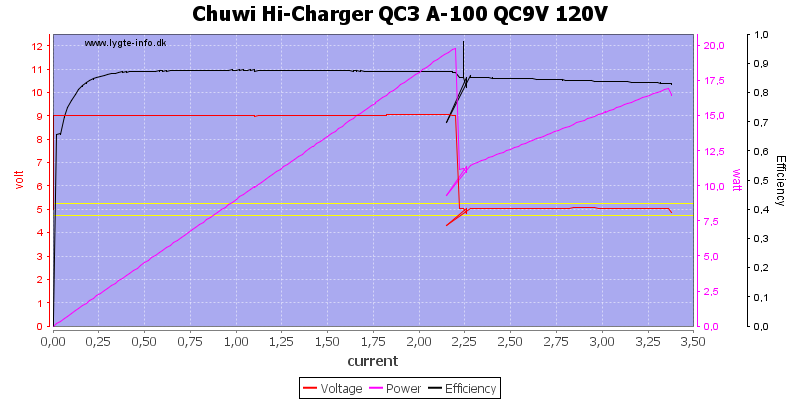
At 9V it is rated 2A and can deliver 2.2A, again very good.
I have been editing the curve where it drops from 9V to 5V, it drops to 0V for a short time.
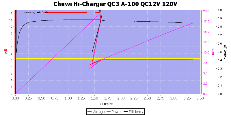
12V is rated 1.5A and can deliver about 1.6A, again very good.
I have been editing the curve where it drops from 12V to 5V, it drops to 0V for a short time.
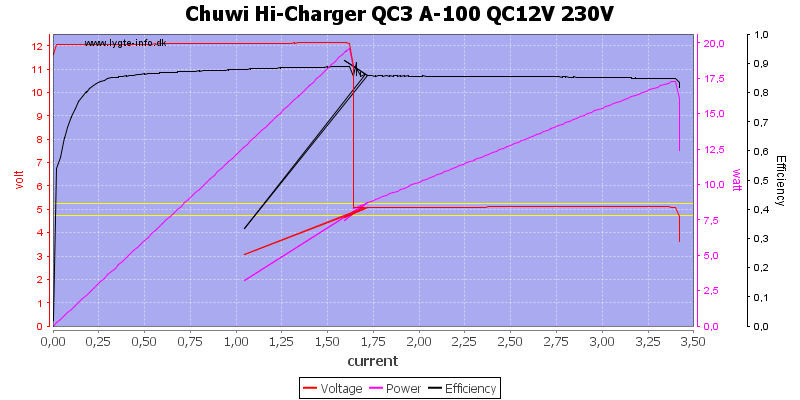
And the same at 230VAC
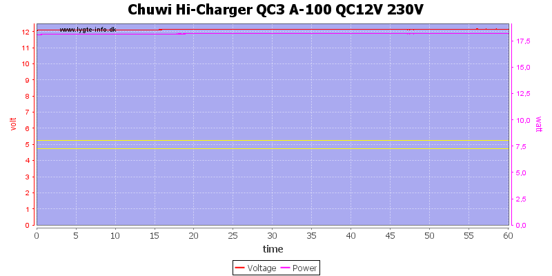
No problem maintaining full rated output power for one hour.
The temperature photos below are taken between 30 minutes and 60 minutes into the one hour test.
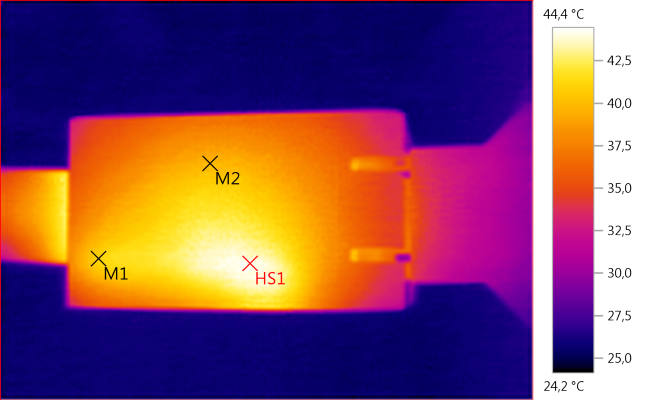
M1: 41,0°C, M2: 39,5°C, HS1: 44,4°C
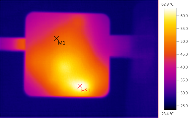
M1: 46,4°C, HS1: 62,9°C
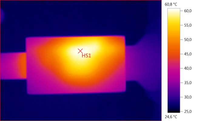
HS1: 60,8°C
HS1 is the mains transformer.
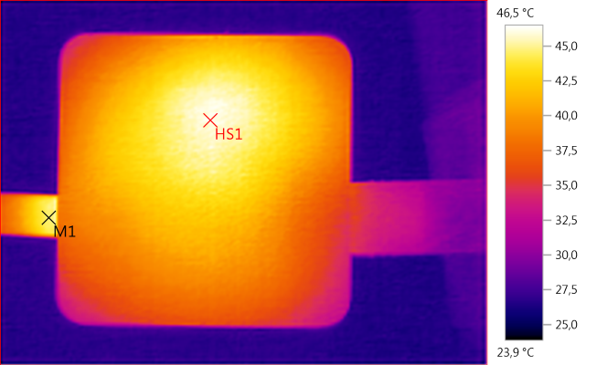
M1: 44,8°C, HS1: 46,5°C
HS1 is the mains transformer.
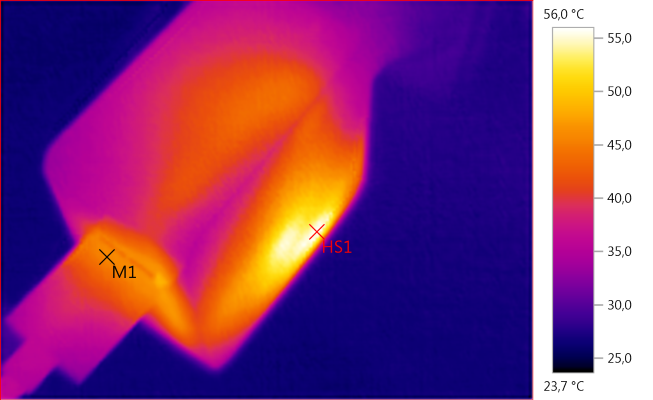
M1: 45,7°C, HS1: 56,0°C

Noise at 0.5A load is: 11mV rms and 157mVpp.

Noise at 1A load is: 14mV rms and 211mVpp.

Noise at 2.5A load is: 13mV rms and 225mVpp.
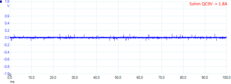
Noise at 9V and 1.8A load is: 12mV rms and 226mVpp.
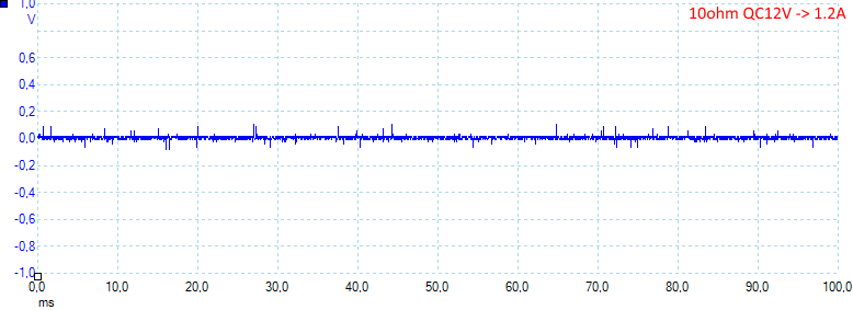
Noise at 12V and 1.2A load is: 11mV rms and 220mVpp.
Tear down
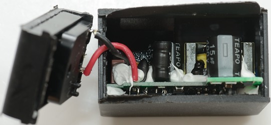
I could not break the glue and had to cut.
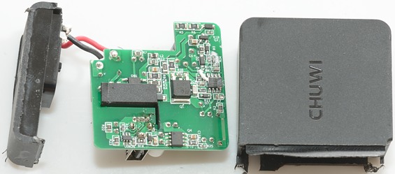
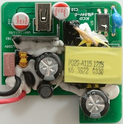
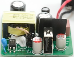
At the mains input is a 2A fuse, a inrush current limiter, a common mode coil and a inductor.
The transformer has flying output leads to improve isolation. Beside the transformer are an opto coupler (U5) and a safety capacitor
Because the output is QC and can deliver up to 12V, the output capacitors are rated for 16V.
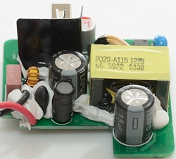
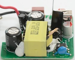
On the first image the inrush current limiter and the inductor are at the edge of the circuit board. The next image has the safety capacitor (CY1).
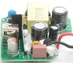
The second image has the red fuse with the common mode coil behind it.
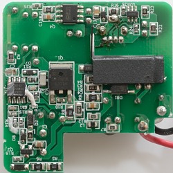
On this side is the bridge rectifier (DB1), the switcher controller (U1), the mains switcher (Q1). On the low volt side is the synchronous rectifier transistor (Q4) and the quick charge controller (U2).
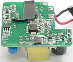
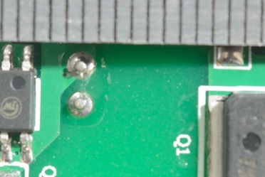
The safety distance look good.
Testing with 2830 volt and 4242 volt between mains and low volt side, did not show any safety problems.
Conclusion
This charger works as a charger is supposed to work: Can deliver the rated current and not much more (I.e. a very good current limiter), fairly low noise, support for QC3 and safe.
The only detail that maybe is missing is auto coding on the output. According to specifications it look like the charger is supposed to have auto coding, but I did not see it. I know that my test will not reveal all auto coding schemes and I could not find data on the chip.
I will call it a good charger.
Notes
Charger was supplied by a Chuwi for review.
Index of all tested USB power supplies/chargers
Read more about how I test USB power supplies/charger
How does a usb charger work?


