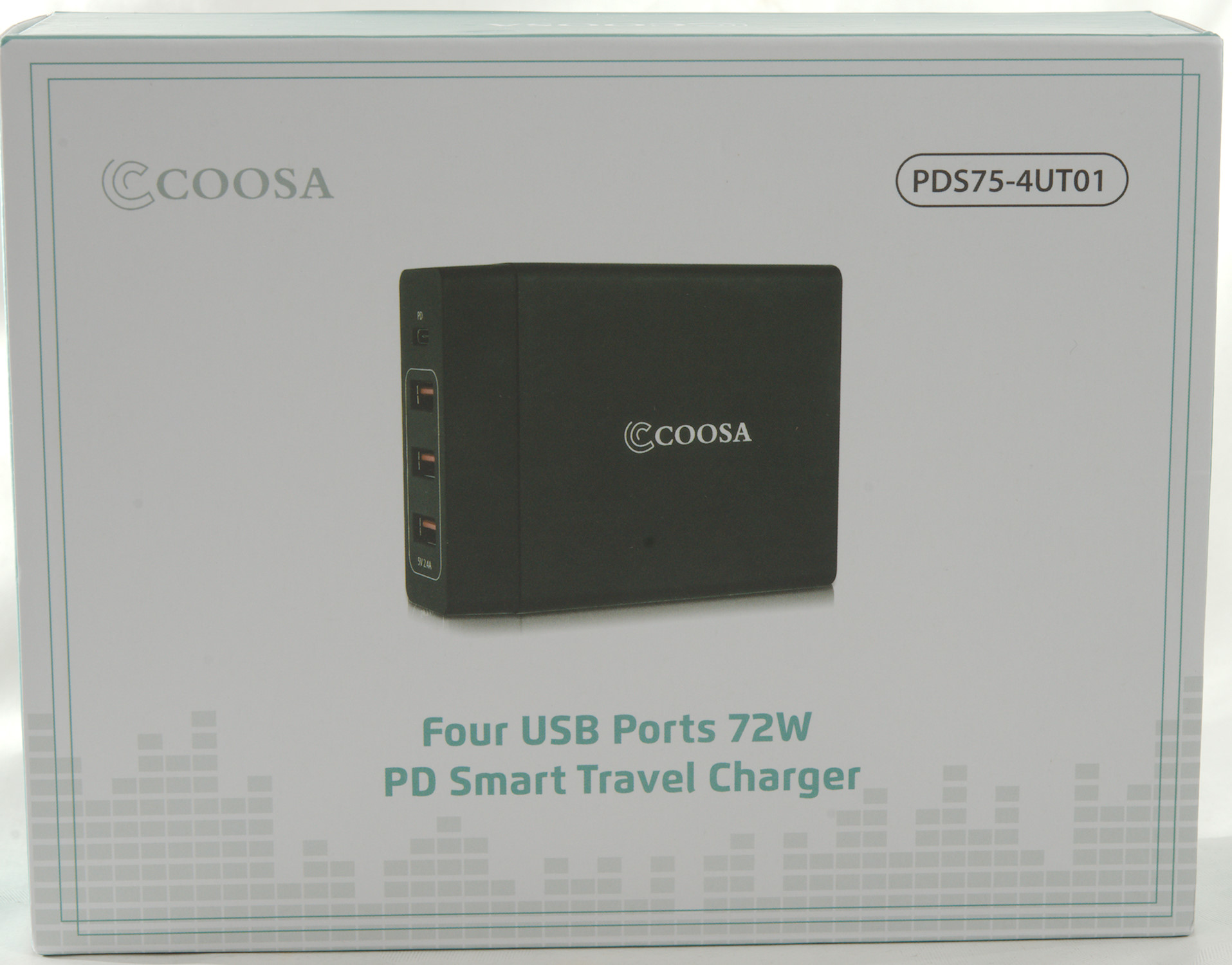
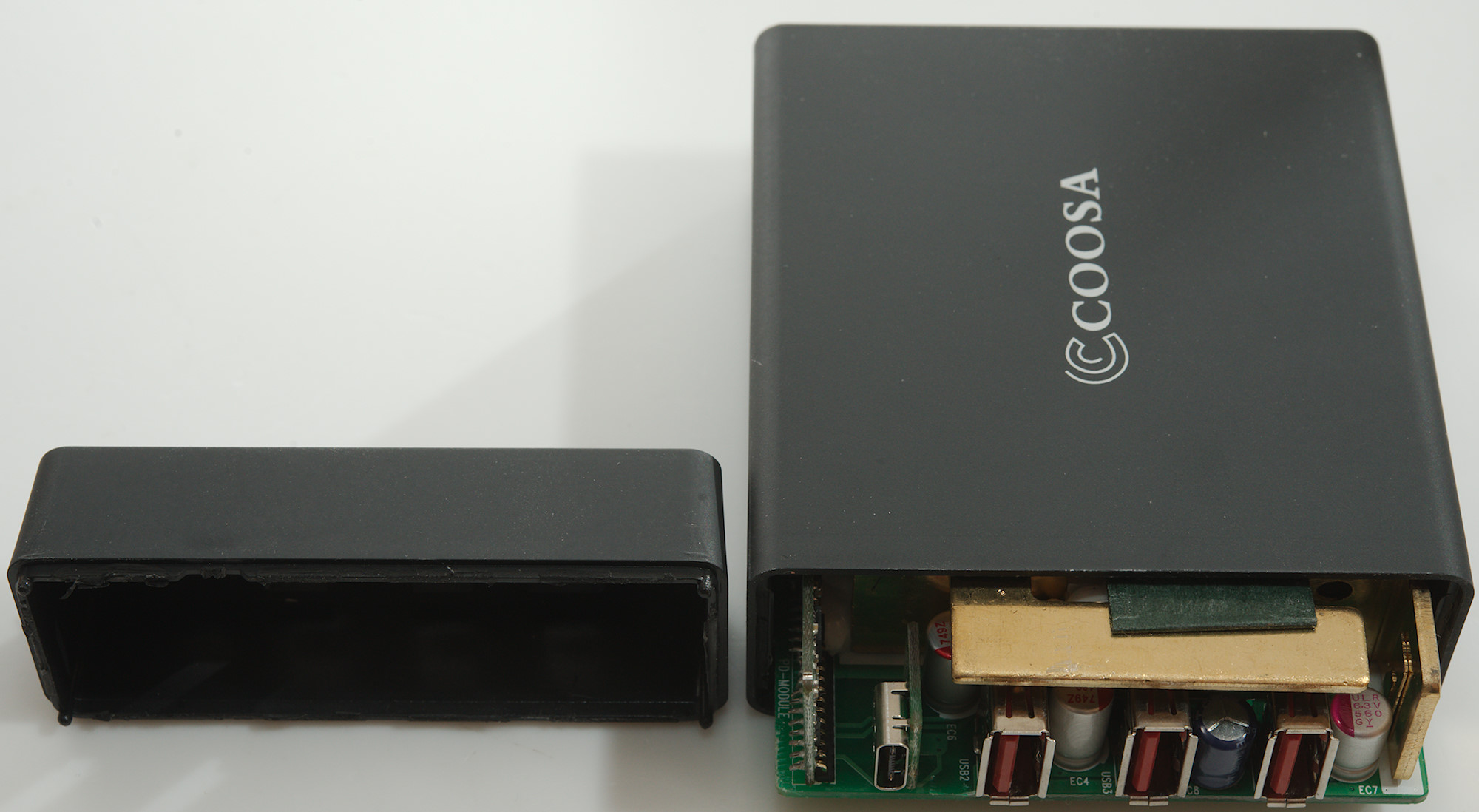
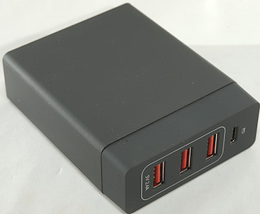
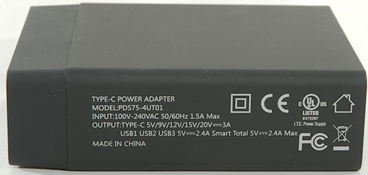
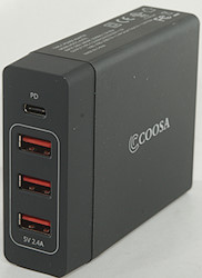
Coosa 5 Port USB Type C PD 72 W Charger PDS75-4UT01
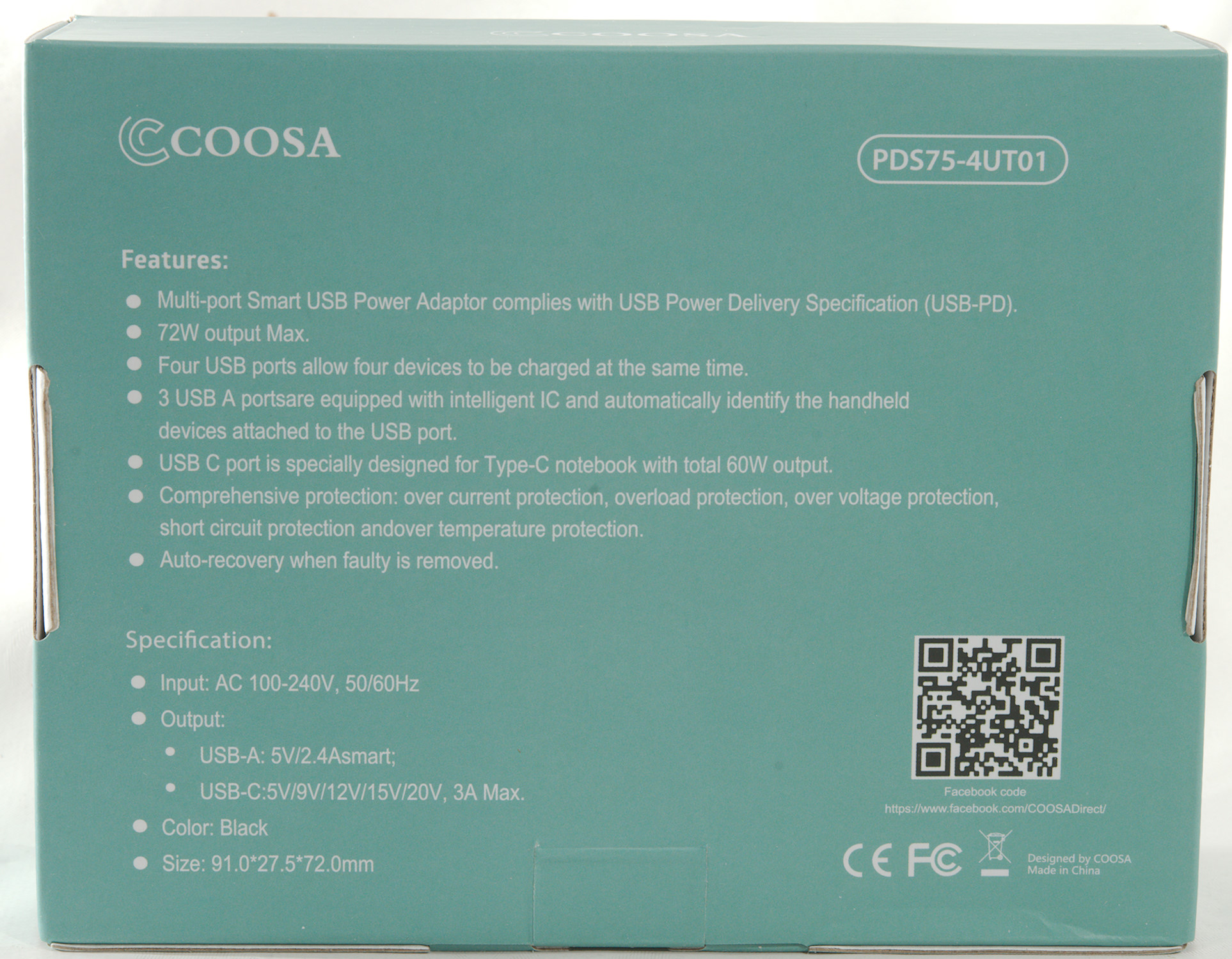
Official specifications:
- Material: Rigid Plastic
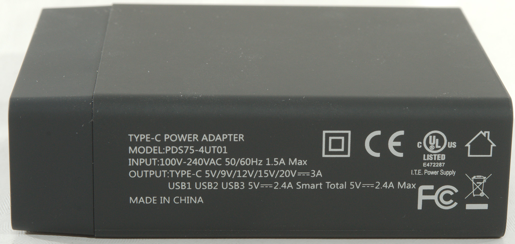
- Input: 100 240Vac 50/60Hz
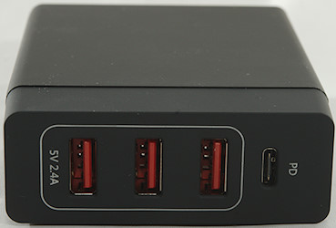
- Output: USB (a): 5 V/2.4 A
- USB c: 5 V and 9 V, 12 V, 15 V, 20 V and 3 A
- AC Discharge Current: 0.25 mA Max at 240 VAC input
- Ripple and noise: Less than 100 mV Vpp
- Switching the delay time: 3s Max
- Rise Time: 20 ms
- USB (a): >= 80%
- USB c: >= 81.4%
- Operating temperatures: 32º F to 140º F (0º ~ 40 °C)
- Storage Temperature Range: -20 ~ 80 °C
- Working relative humidity: 5% ~ 90% RH
- Colour: Black
- Size: 91 x 75 x 27.5 mm
- Weight: 220 g (Main body without mains cable)
I got it from amazon.de dealer: COOSA®
I wonder about some of the specifications, the "Discharge current" must be the leak from mains to low volt side, the rules says it has to be below 0.25mA, this matches the specification (A measurement also shows it to be below 0.25mA).
The two percent specifications must be efficiency and matches fairly well with my measurements.
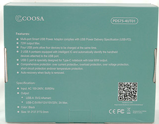
I got it in a cardboard box with specifications on the back.
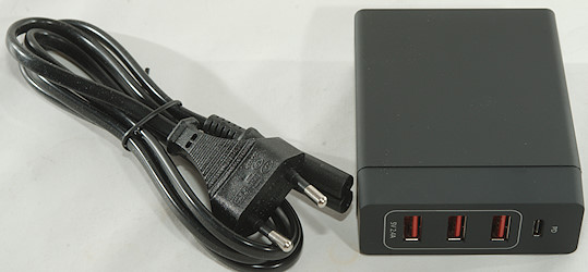
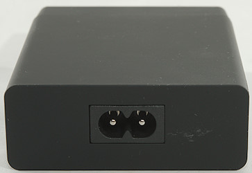
It contained the charger and a mains cable.
Measurements
- Power consumption when idle is 0.16 watt
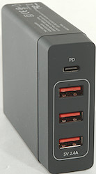
- PD output supports: 5V 3A, 9V 3A, 12V 3A, 15V 3A, 20V 3A
- PD output also support DCP and QC2
- Default PD output is off.
- Regular usb output are auto coding with Apple 2.4A, Samsung and DCP
- Regular usb outputs are in parallel.
- PD and regular usb are isolated fro each other.
- Weight: 232g
- Size: 91 x 72.2 x 27.6mm
The regular usb output can deliver 3.5A, this is a bit high for a 2.4A rating.
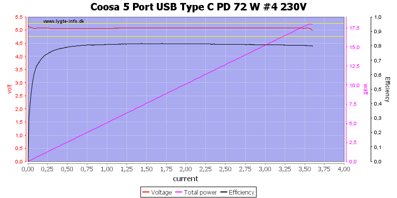
Another regular usb output can deliver the same.
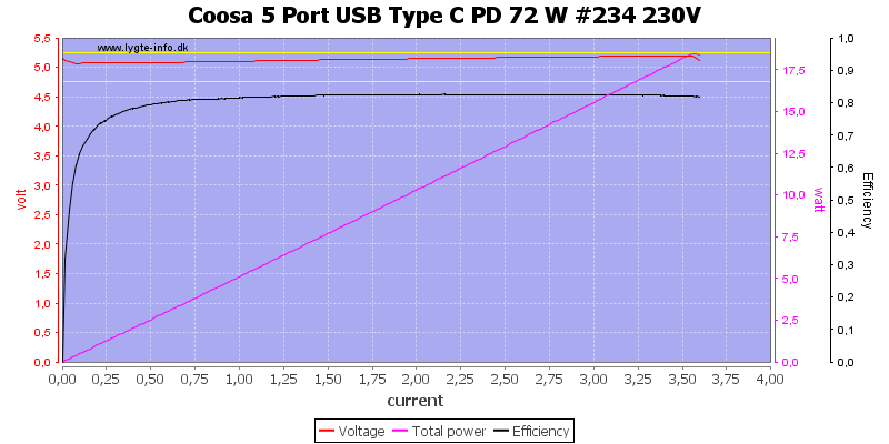
Running all 3 usb outputs in parallel is also the same.
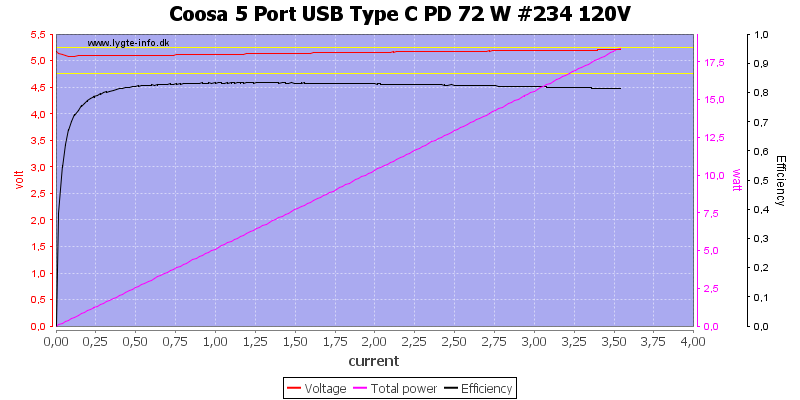
Not much difference at 120VAC.
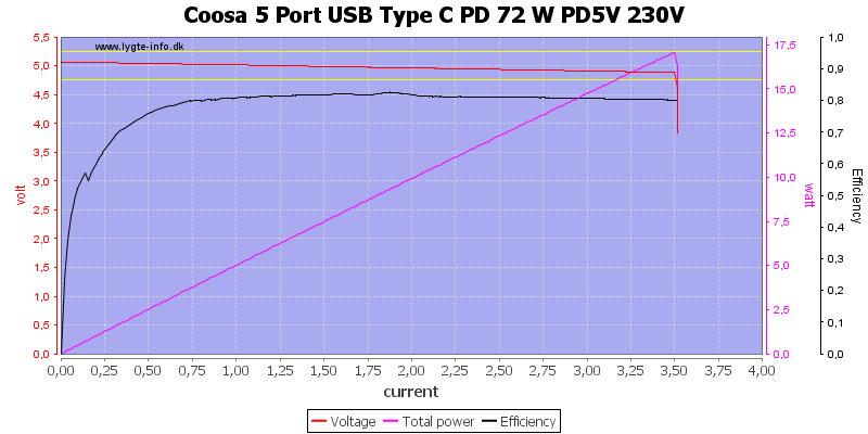
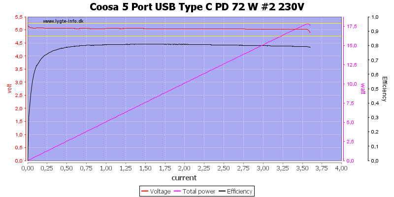
PD at 5V can deliver 3.5A, this is fine for a 3A rated output.
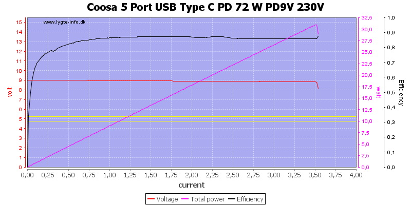
At 9V it is also 3.5A
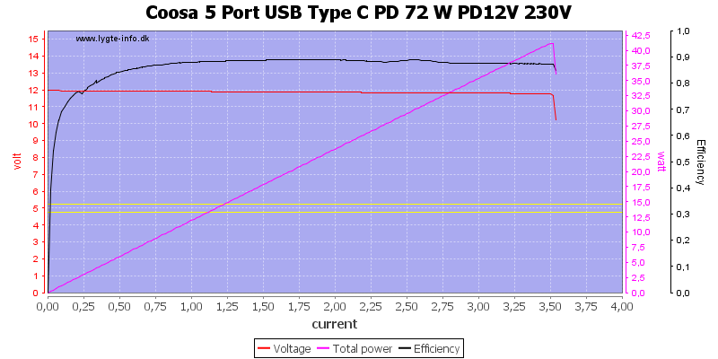
And the same at 12V
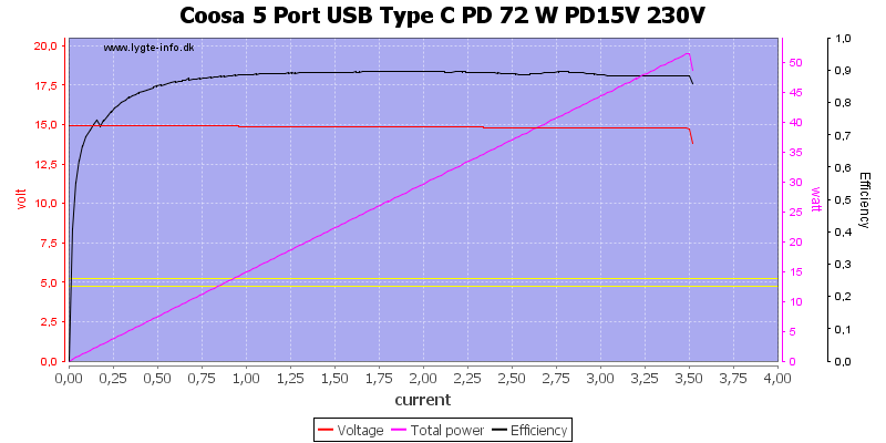
And at 15V
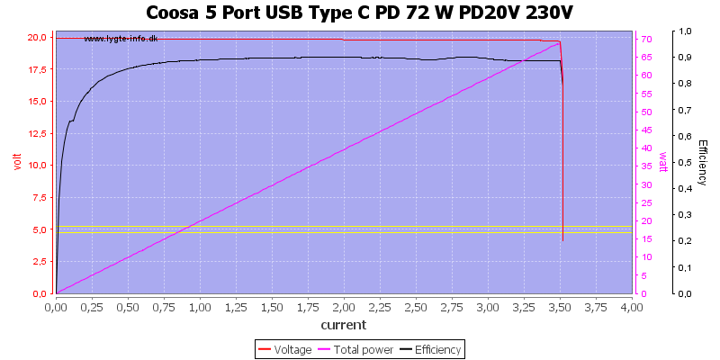
And finally at 20V, this is the 60W rated output.

The output is the same at 120VAC
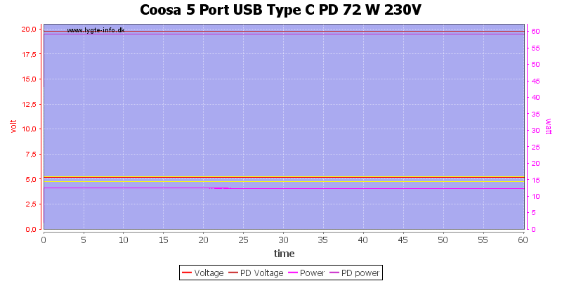
For a load test I used 20V 3A and 5V 2.4A for one hour, it worked fine.
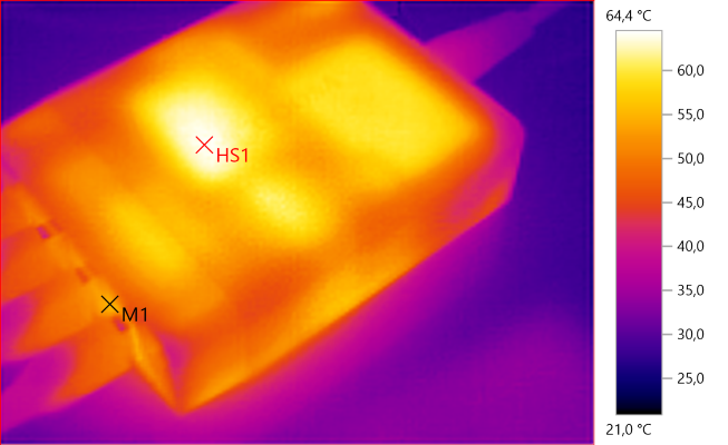
The temperature photos below are taken between 30 minutes and 60 minutes into the one hour test.
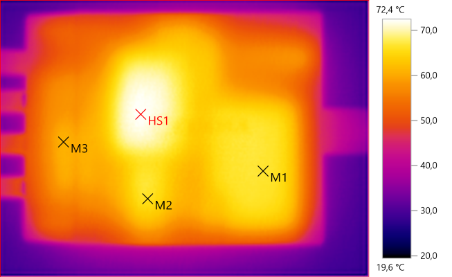
M1: 66.7°C, M2: 66.1°C, M3: 60.7°C, HS1: 72.4°C
This IR picture is a nice map of the inside: HS1 is the PD transformer, M2 is the regular usb transformer, M1 is the heatsink for the switcher transistors and M3 is the heatsink for the PD rectifier.
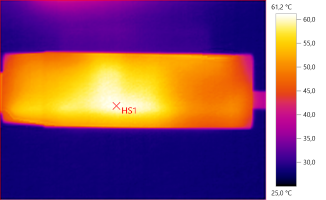
HS1: 61.2°C
HS1 is the regular usb transformer.
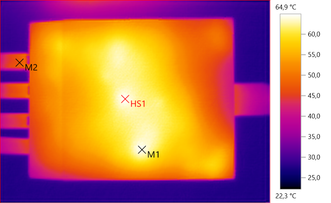
M1: 64.5°C, M2: 47.6°C, HS1: 64.9°C
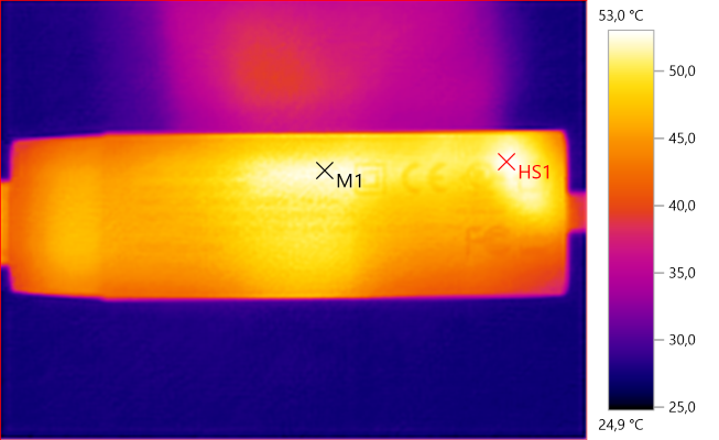
M1: 52.3°C, HS1: 53.0°C
M1: 54.7°C, HS1: 64.4°C
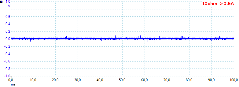
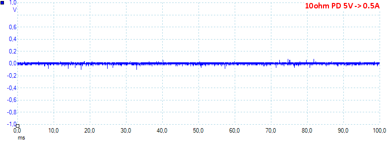
At 0.5A the noise is 16mV rms and 253mVpp.
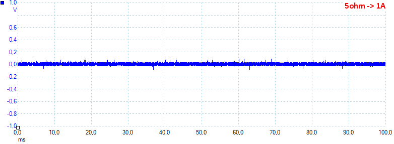
At 1A the noise is 25mV rms and 216mVpp.
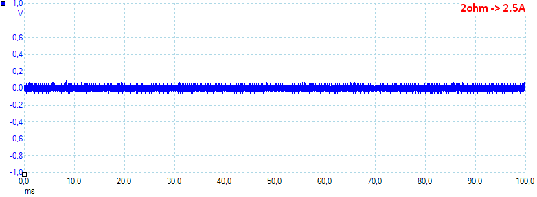
At 2.5A the noise is 32mV rms and 182mVpp.
At PD 5V 0.5A the noise is 16mV rms and 239mVpp.
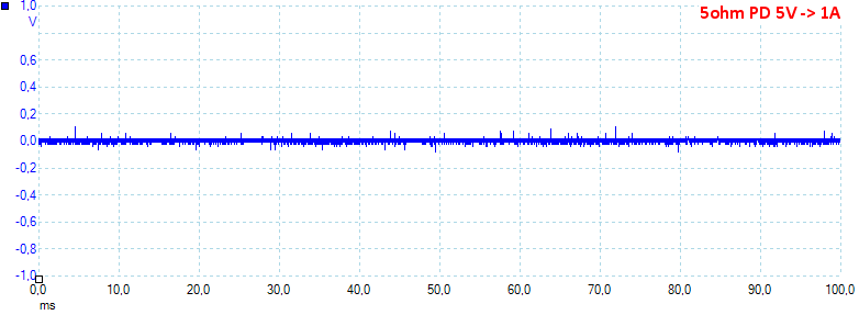
At PD 5V 1A the noise is 16mV rms and 259mVpp.
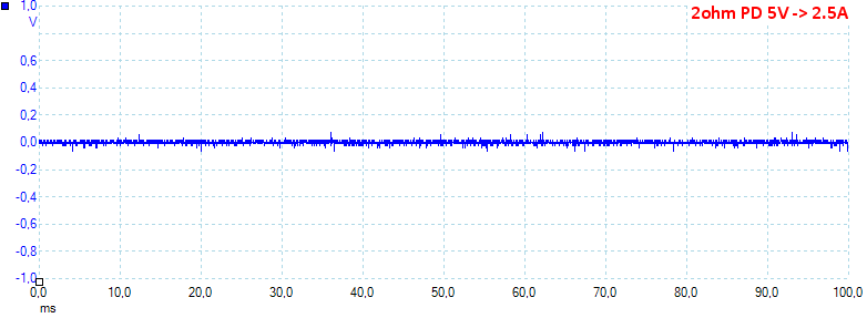
At PD 5V 2.5A the noise is 15mV rms and 342mVpp.
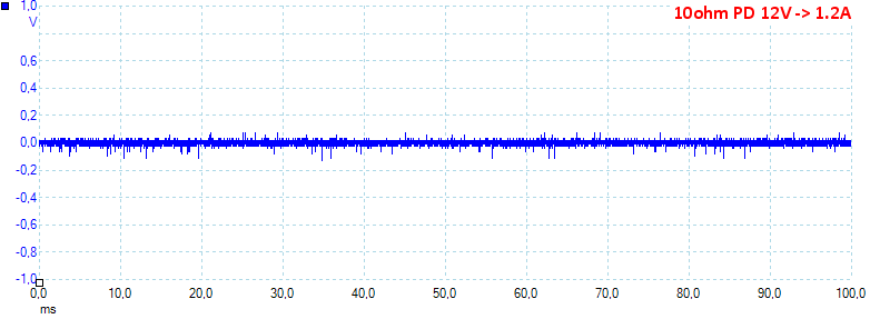
At PD 12V 1.2A the noise is 20mV rms and 264mVpp.
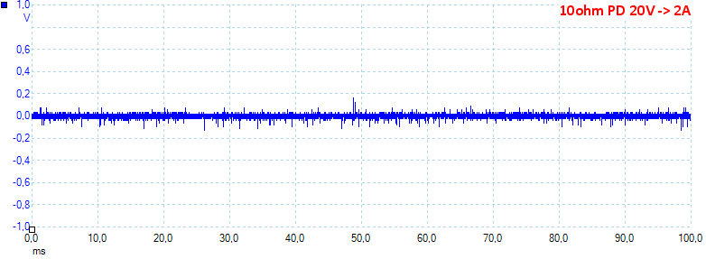
At PD 20V 2A the noise is 23mV rms and 321mVpp, all noise values are fairly low.
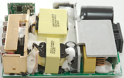
Tear down

This type of charger is usual very easy to open: mount the front in a vice and give the enclosure a whack with a mallet, this breaks the glue holding the front. In this case there was a problem, I could not pull the circuit board out. This improves the safety of the charger, because there is nothing dangerous to touch on the exposed parts.
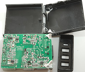
I had to cut before I could get the circuit board out, somebody had used the white stuff to glue the circuit board in place.
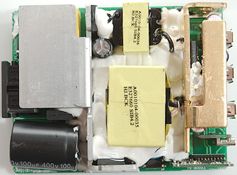
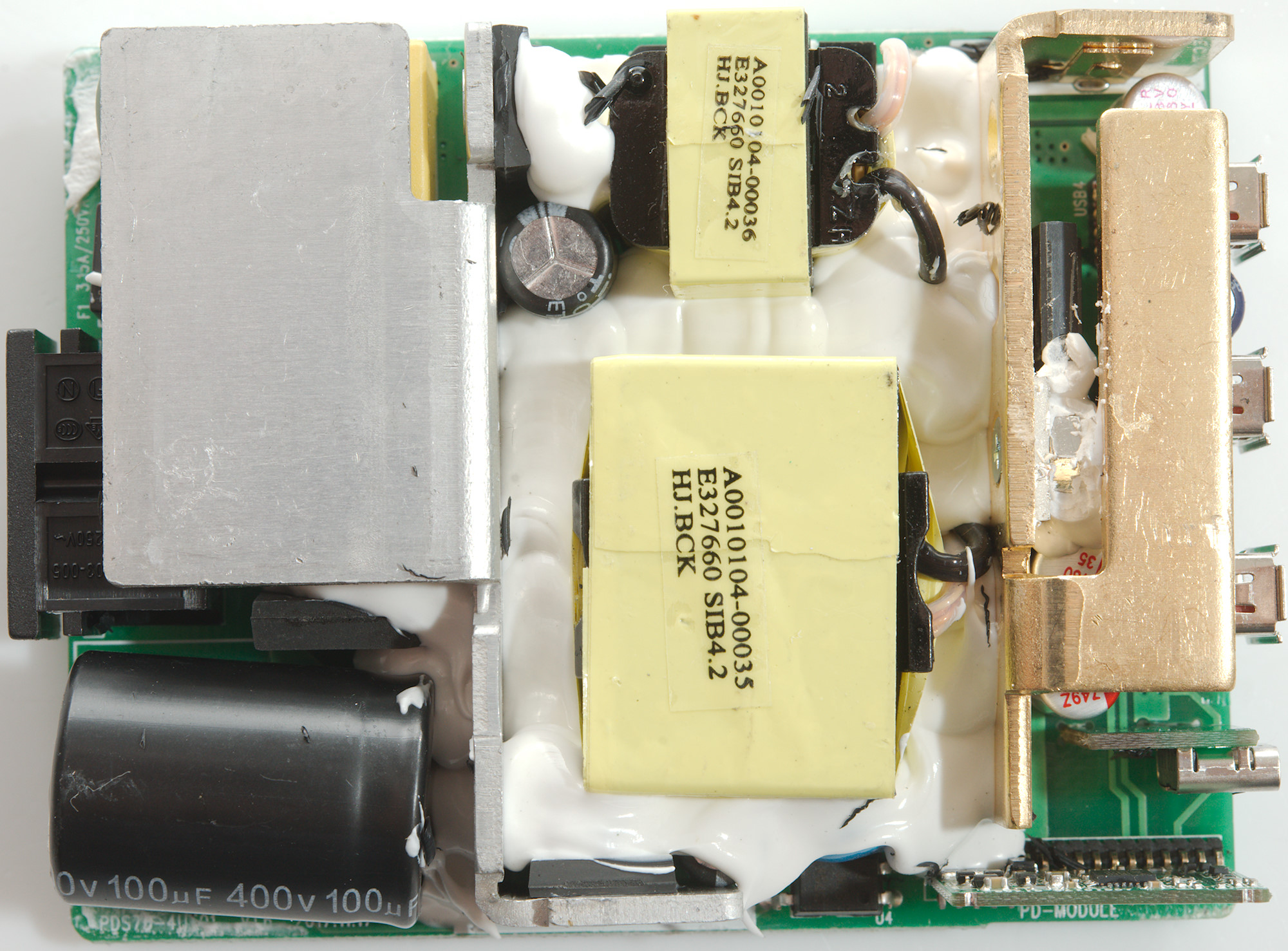
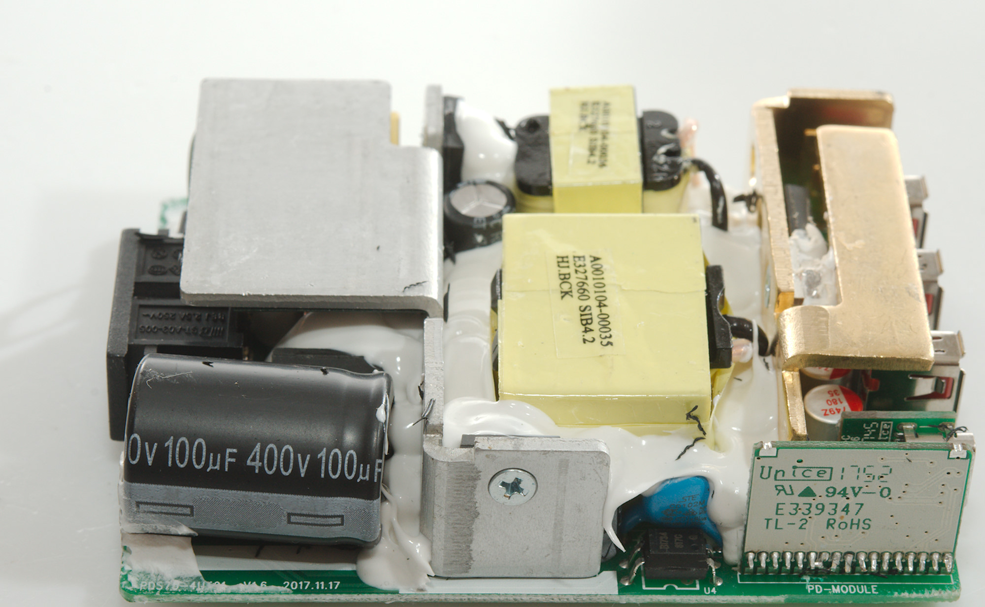
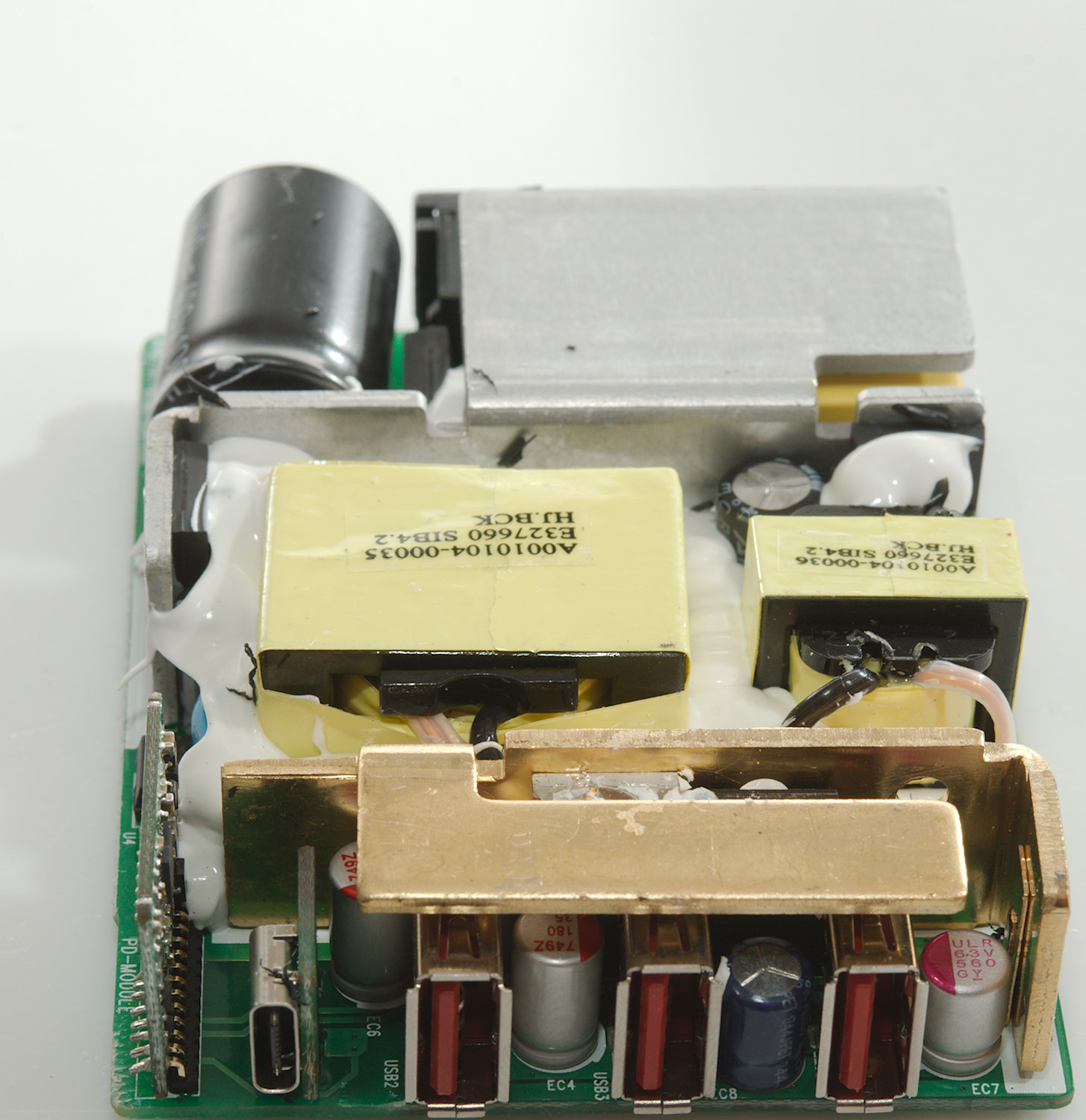
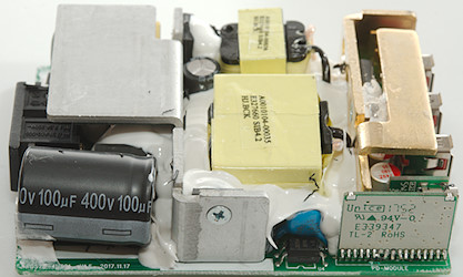
With all the white stuff and heatsinks some of the parts are hidden, but it is still possible to see most of the circuit. Next to the large mains smoothing capacitor is a bridge rectifier.
On the blank heatsink are two mains switcher transistor, one for 5V and one for PD, next to the PD transistor is the opto feedback (U4) and a blue safety capacitor.
The large transformer is for the 60W PD output and the small transformer is for the 12W normal usb output.
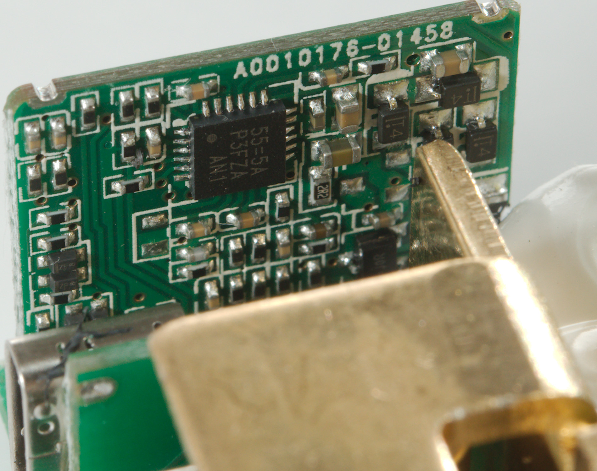
On the golden heatsink is mounted a transistors for synchronous rectification together with a diode, both for PD. There two small circuit board, one for the USB-C connector and one for the PD controller.
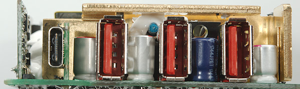
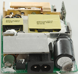
There is not much to see from the front. The board with the USB-C connector do not have any parts on it, there is 6 connections to the main circuit board. 2 power and 4 control.
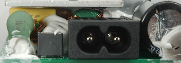
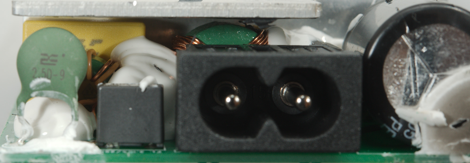
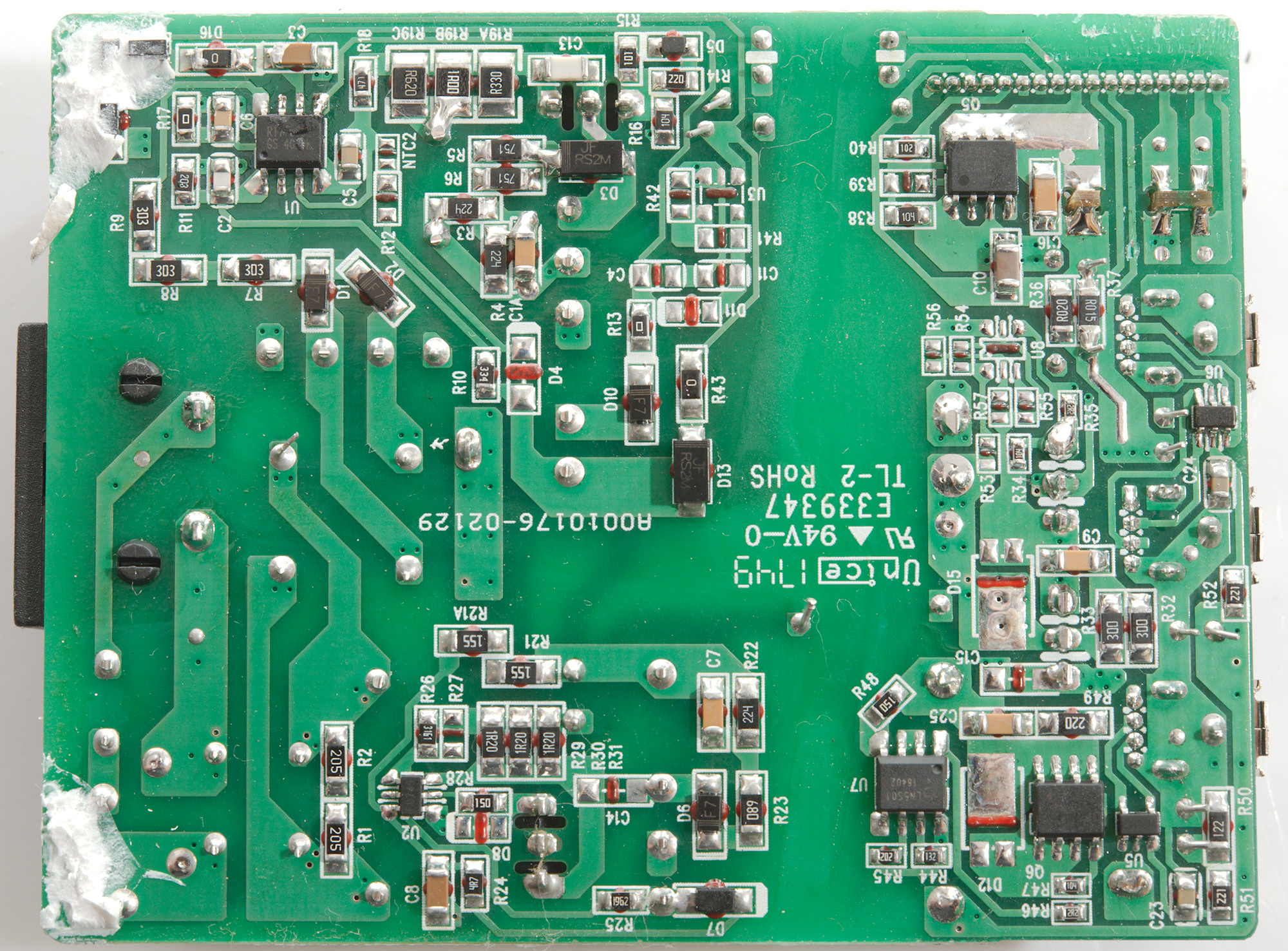
From the back a fuse, a inrush current limiter and two common mode coils can be seen.
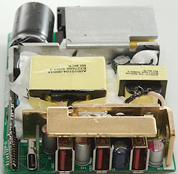
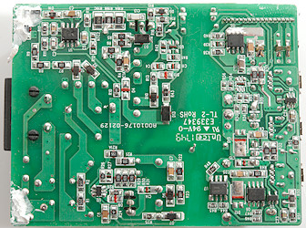
On the mains side is two switchers one for PD (U1) and one for 5V (U2: Marked FD745). On the low volt side for 5V there is a synchronous rectifier controller (U7: LN5S01) that controls a SMD transistor (Q6) to rectify normal usb. There are two auto coding chips (U5: CX1901A, U6: CX2901A).
The PD output only has a on/off switch (Q5) on this side, the rest is on a small circuit board.
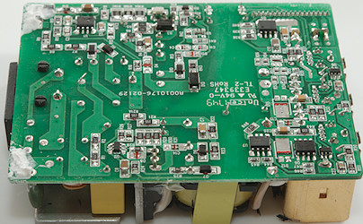
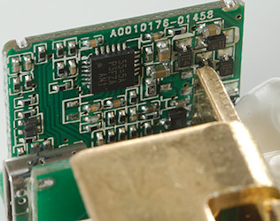
This small circuit board handles the PD, both the protocol, the regulation to the opto feedback and the synchronous rectification controller.
The distance between mains and low volt side looks fine.
The charger passed the 2830 volt and 4242 volt test, this means it is it is fairly safe.
Conclusion
As a 60W PD supply this charger is fine, but as a regular usb charger not as much, with only 2.4A for 3 outputs is is serious under powered, it only has power for one regular usb output. I did not see any safety problems in it.
Notes
Index of all tested USB power supplies/chargers
Read more about how I test USB power supplies/charger
How does a usb charger work?