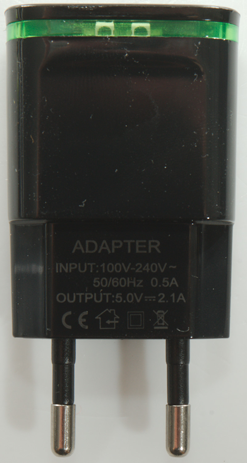
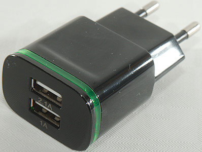
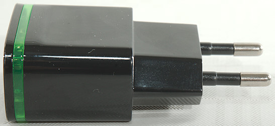
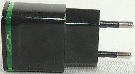
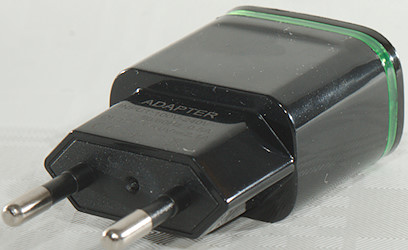
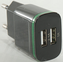
Dual USB Charger 2.1A
Official specifications:
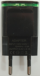
- Input voltage: 100-240 V 50-60Hz
- Output: 5.0V 2.1A
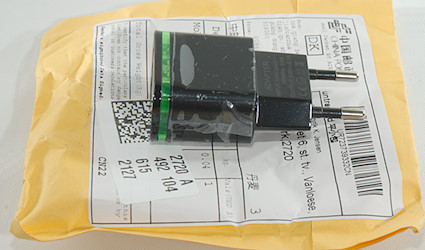
It is a cheap charger and as usual is is in a envelope without anything else.
Measurements
- Power consumption when idle is 0.27 Watt
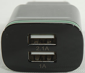
- 1A USB output is coed as Samsung
- 2.1A USB output has unknown coding.
- The output are in parallel.
- There is some leds behind the green plastic.
- Weight: 32.3g
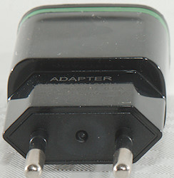
- Size: 71.2 x 37.7 x 24.6 mm
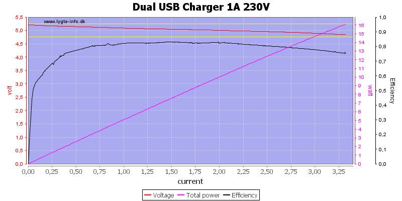
The charger can deliver over 3A on the 1A output before it has problems.
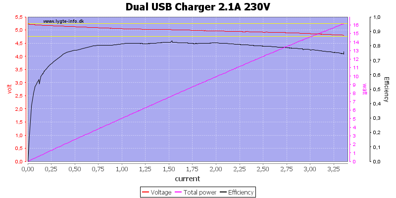
And the same on the 2.1A output
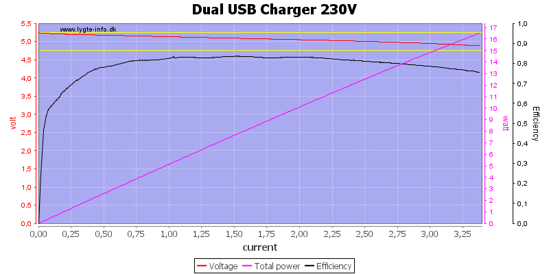
Using them in parallel do not change the current.
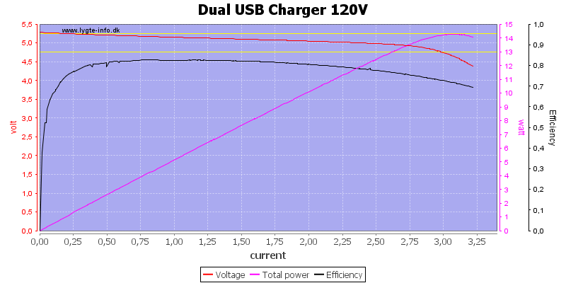
The current is lower at 120VAC and the regulation is not very good above 2.7A
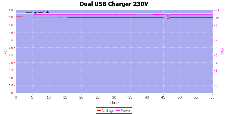
The charger can deliver 2.1A for one hour.
The temperature photos below are taken between 30 minutes and 60 minutes into the one hour test.
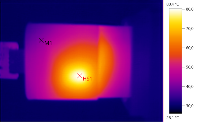
M1: 41.8°C, HS1: 80.4°C
HS1 is the transformer.
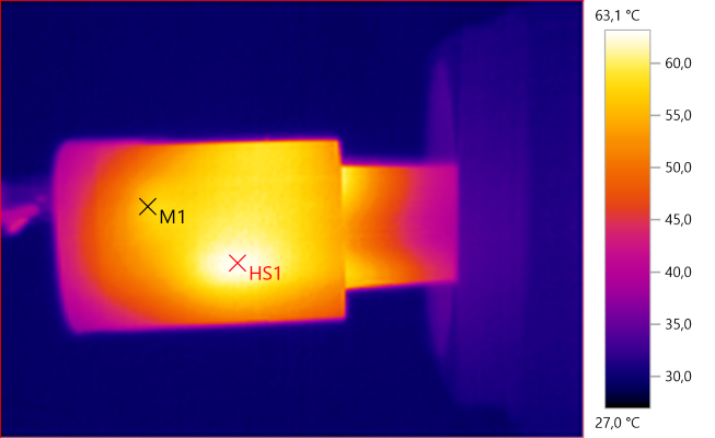
M1: 57.0°C, HS1: 63.1°C
Here HS1 is most likely the rectifier diode transferring heat through the circuit board.
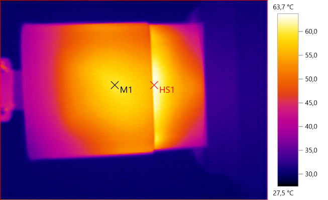
M1: 59.7°C, HS1: 63.7°C
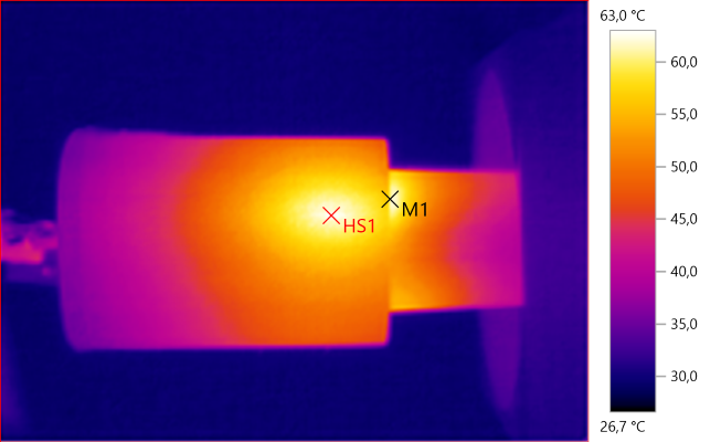
M1: 60.6°C, HS1: 63.0°C
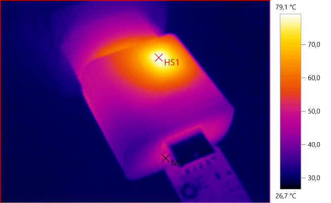
M1: 46.9°C, HS1: 79.1°C
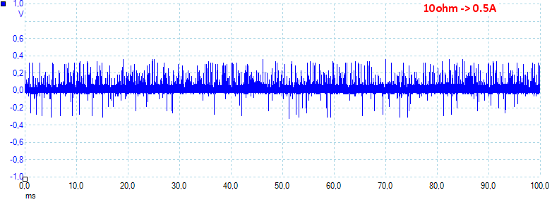
At 0.5A the noise is 66mV rms and 723mVpp.
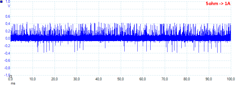
At 1A the noise is 89mV rms and 697mVpp.
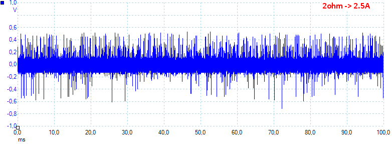
At 2.5A the noise is 127mV rms and 1438mVpp, it is a lot of noise.
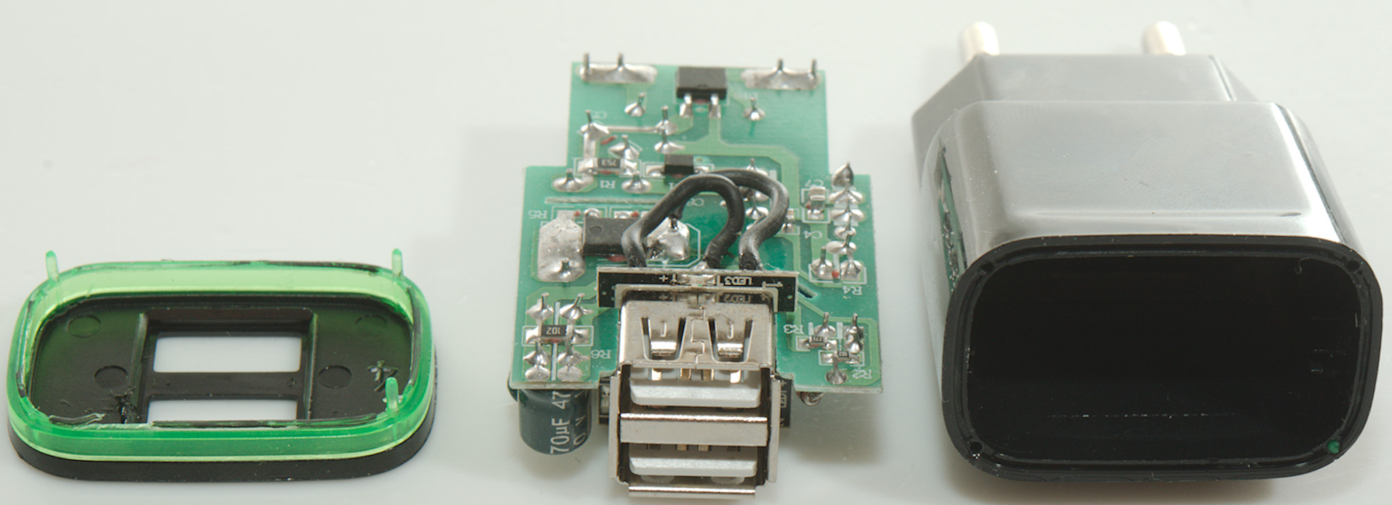
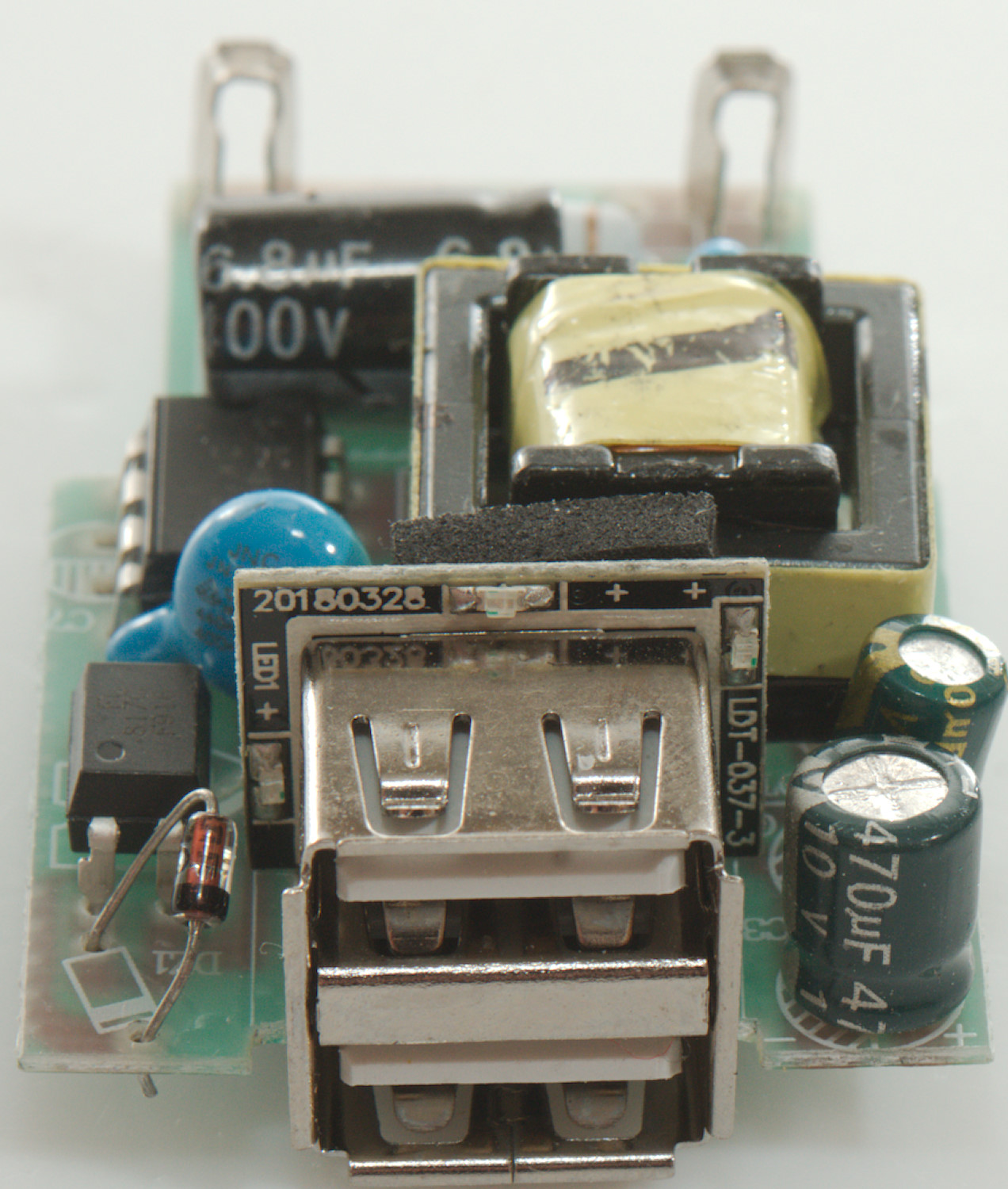
Tear down
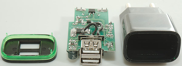
Using my vice to apply some pressure just below the green band broke the glue and I could open it.

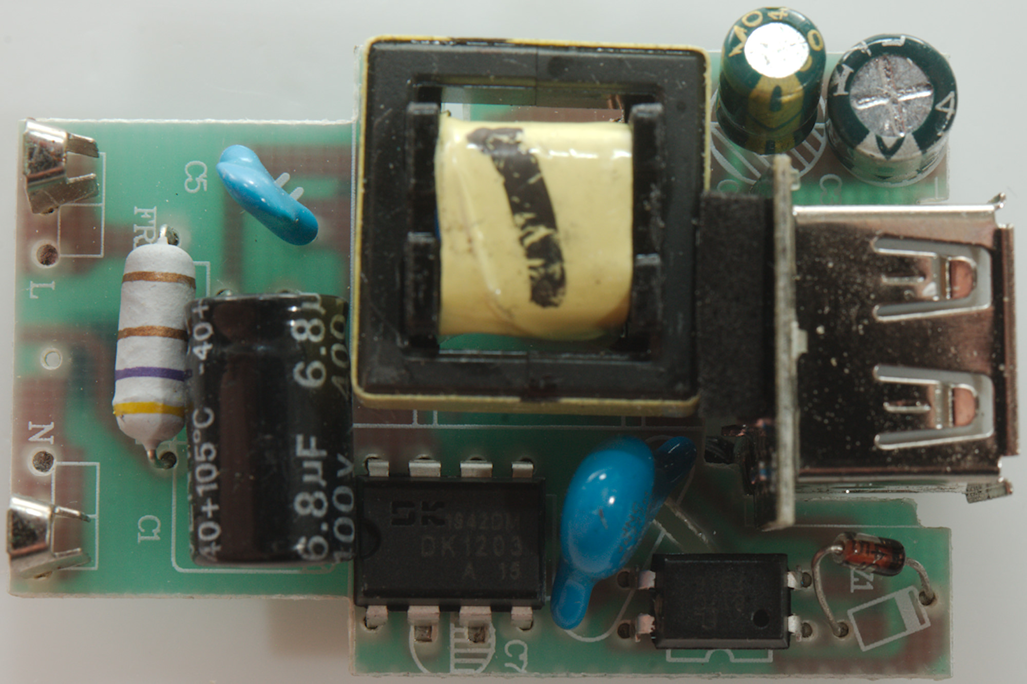
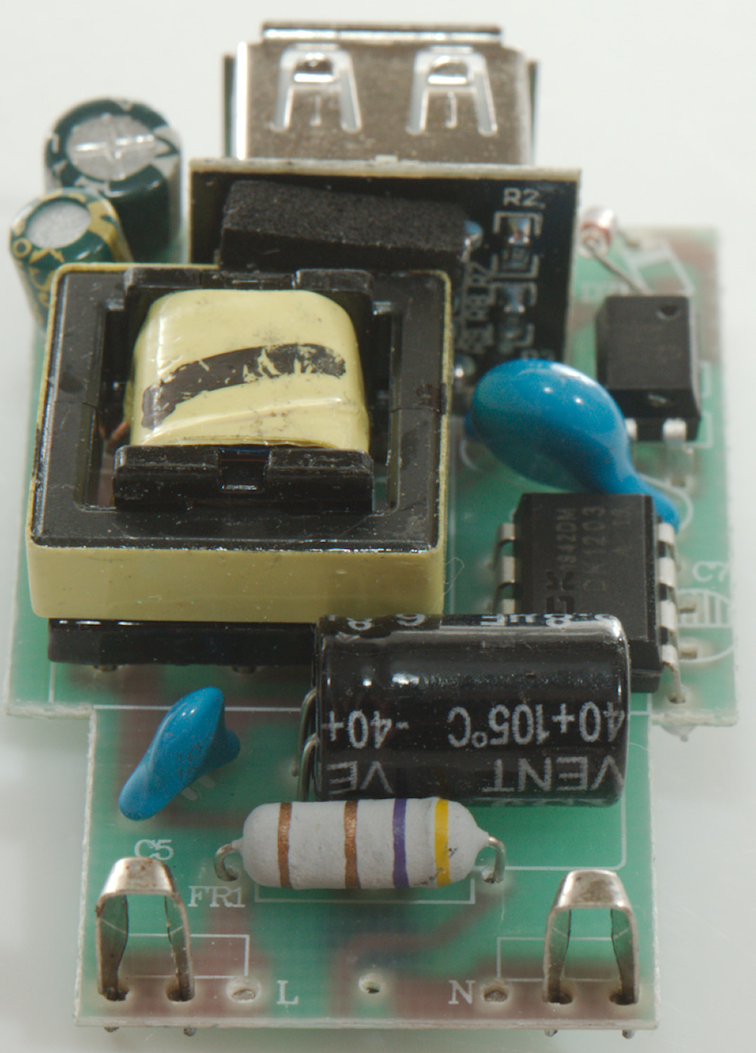
The circuit is fairly simple, at the input is a fusible resistor (FR1), the mains switcher is a single chip (DK1203) next to the safety capacitor (CY1) and the opto coupler for feedback. On the low volt side the voltage is regulated with a Zener diode (DZ1) and not the usually reference chip, this means wider tolerance on the output voltage.
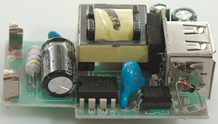


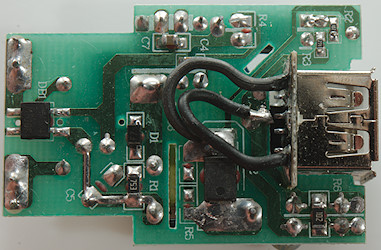
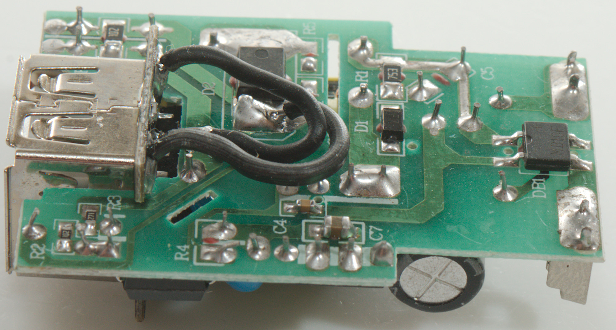
On this side is the bridge rectifier (DB1) and the low volt rectifier diode (D2).
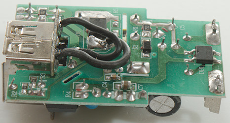
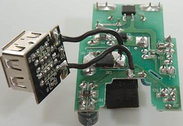
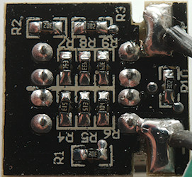
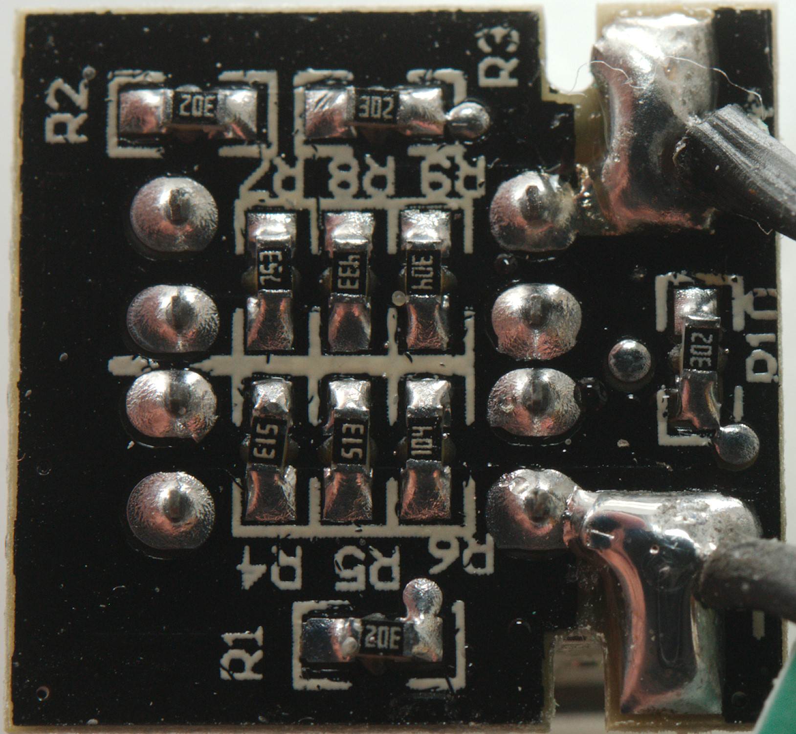
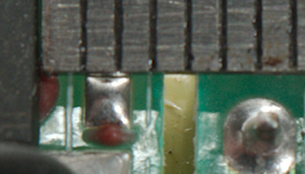
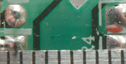
The USB connectors is on their own circuit board, together with the coding resistors.
There are 4 leds on the other side to light the green band.
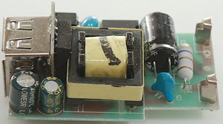
With a slot in the circuit board the distance between mains and low volt side only needs to be 4mm, here it is around 3mm.
When there is no slot the distance must be above 6mm, here it is around 4mm.
Testing with 2830 volt and 4242 volt between mains and low volt side, did not show any safety problems.
Conclusion
The charger can only sustain maximum output on one port and has lots of noise, strange coding and safety is not that good with the isolation distances on the circuit board being significant below legal requirements.
Notes
Index of all tested USB power supplies/chargers
Read more about how I test USB power supplies/charger
How does a usb charger work?