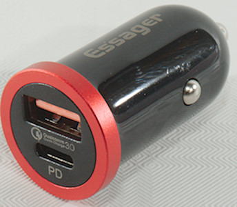
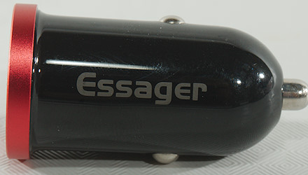
Essager QC+PD Car charger FQC23
Official specifications:
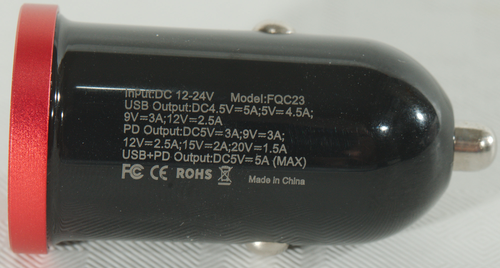
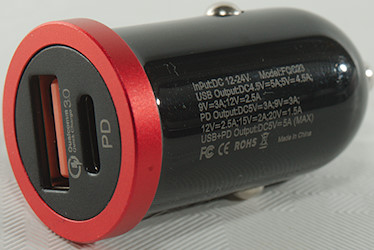
- Input: 12-24V
- USB: 4.5V 5A, 5V 4.5A, 9V 3A, 12V 2.5A
- PD: 5V 5A, 9V 3A, 12V 2.5A, 15V 2A, 20V 1.5A
- USB+PD: 5V 5A
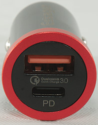
- Multiple protocols: QC3.0 QC2.0, Huawei SCP, Huawei FCP, Samsung FCP
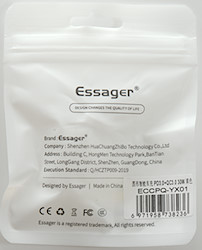
I got it from aliexpress dealer: ESSAGER Official Store
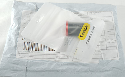
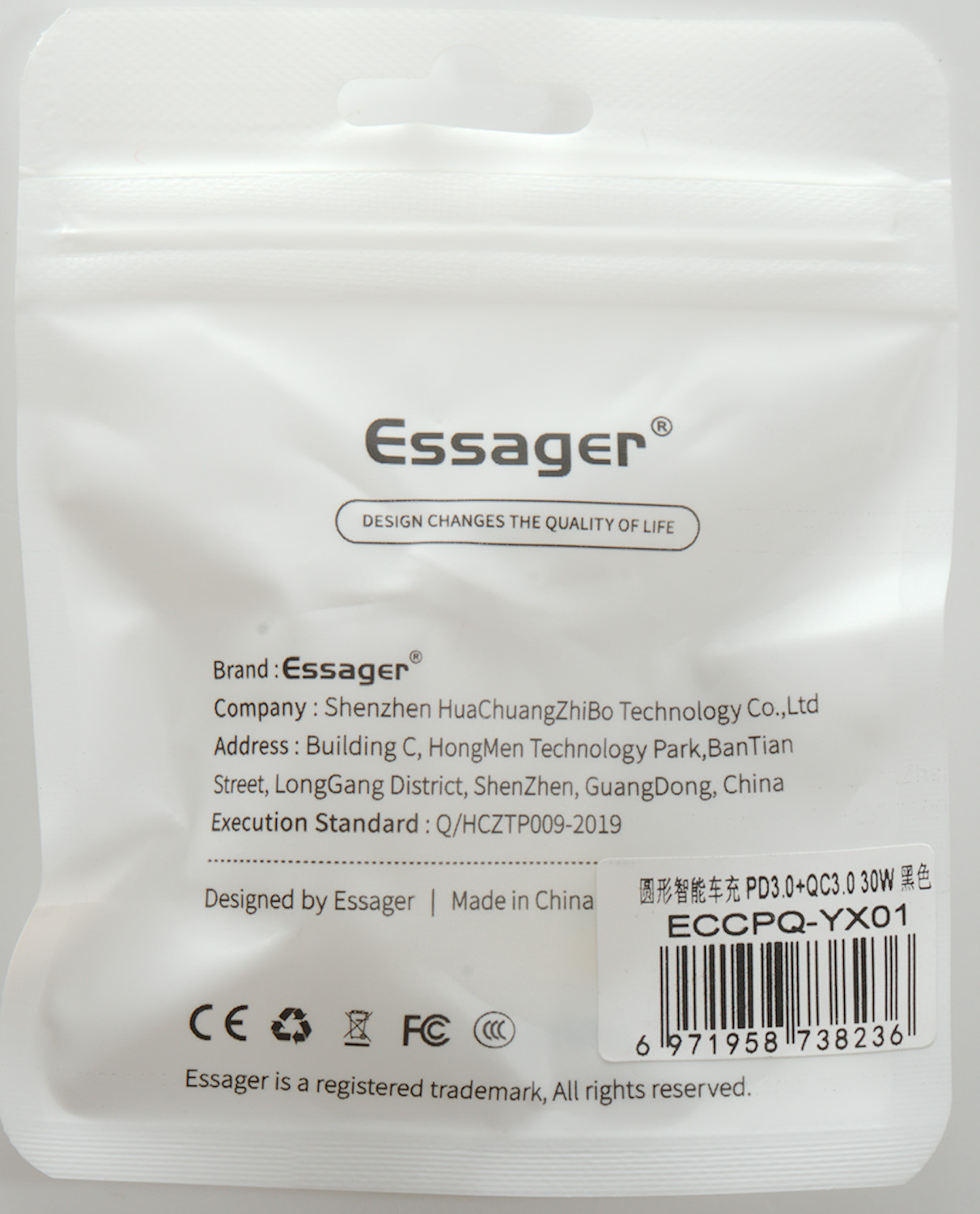
The charger was packed in a plastic bag inside an envelope, very common for Ebay.

Measurements
- PD output: 5V 2A, 9V 3A, 12V 2.5A, 15V 2A, 20V 1.5A, PPS:3-5V 3A, PPS:3-11V 3A
- Minimum QC3 voltage is 3.7V
- 20V output is enabled at 20.5V and disabled at 19.0V
- 15V output is enabled at 14.7V and disabled at 13.2V
- 12V output is enabled at 11.4V and disabled at 10.8V
- USB output is coded as Apple 2.4, DCP, DCP, Samsung, QC3
- Due to the automatic port switching I could not detect more protocols on either USB or PD.
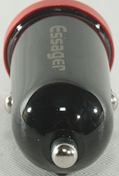
- There is a white light inside the charger.
- Power consumption when idle is about 5mA on 12V and 24V
- The chip used is rated for 36V and input capacitor 35V.
- Weight: 15.4g
- Length: 46mm
- Diameter: 24mm
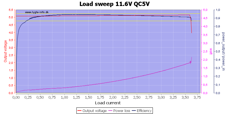
I did not see the 4.5A rating for the QC output and it would be to high for a USB connector anyway, but it can deliver about 3.6A
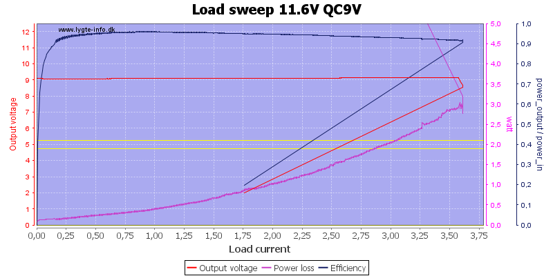
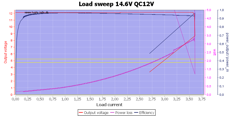
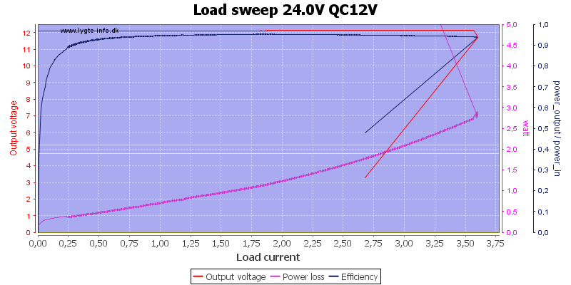
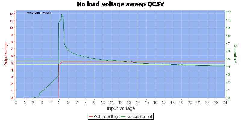
In can deliver 3.6A at any QC voltage,
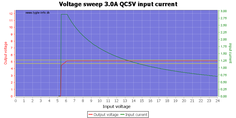
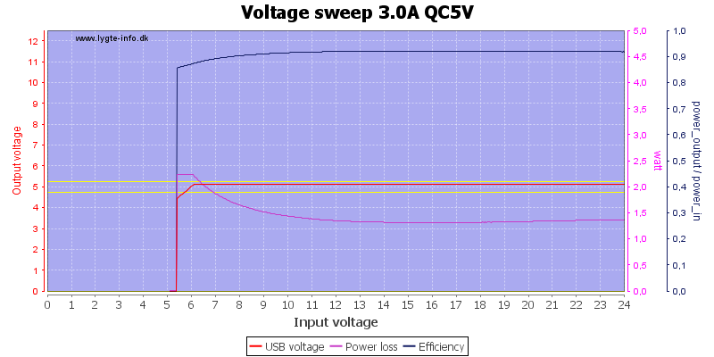
At 5V it can maintain output down to 6V
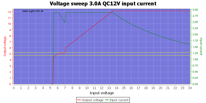
The 12V QC output will be 12V down to 13.5V when drawing 3A.
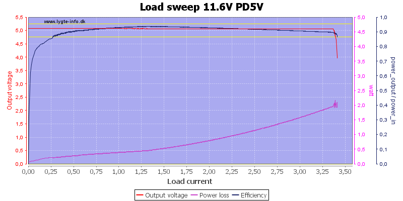
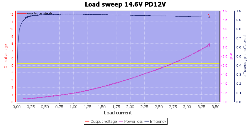
The PD output has a slightly lower current limit of around 3.3A, this matches the 3A marked on the charger, the electronic marking says 2A for regular 5V and 3A for variable voltage.
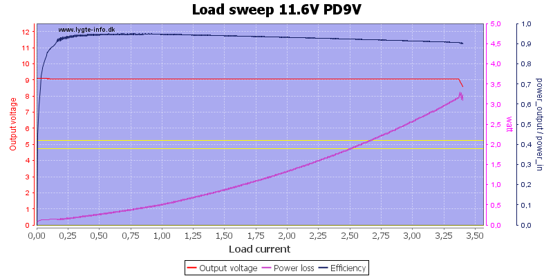
THe 9V PD output is supposed to deliver 3A and do it.
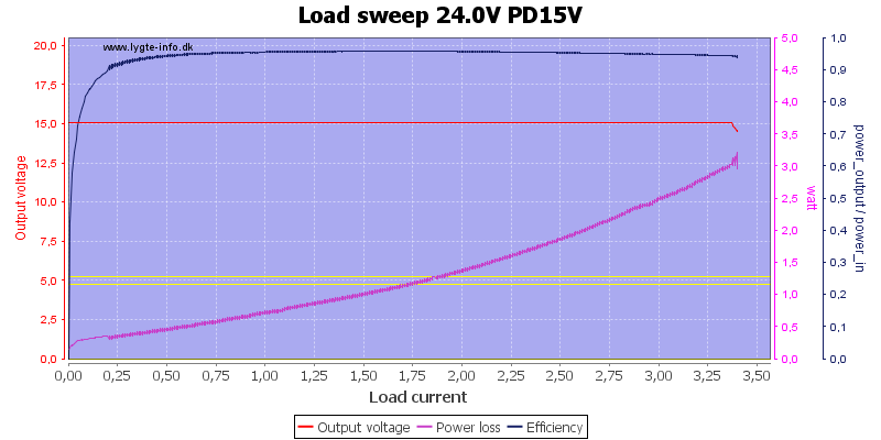
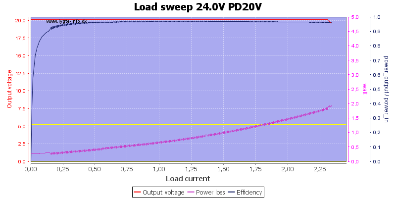
The higher PD voltages also deliver 3A, but the Electronic marking is lower. Also note that 15V and 24V will only work in a 24V car system.
The current consumption is fairly independent of input voltage.
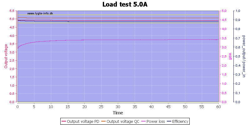
Using a PD resistive coding I could draw 2.5A from both QC and PD output for 1 hour, using any electronic coding (QC or PD) the other output would switch off.
The temperature photos below are taken between 30 minutes and 60 minutes into the one hour test.
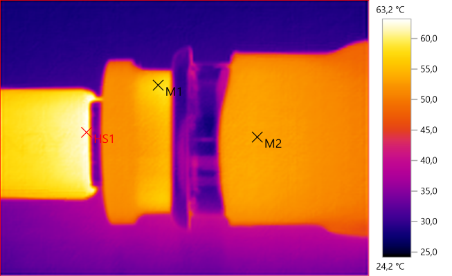
M1: 57.6°C, M2: 53.5°C, HS1: 63.2°C
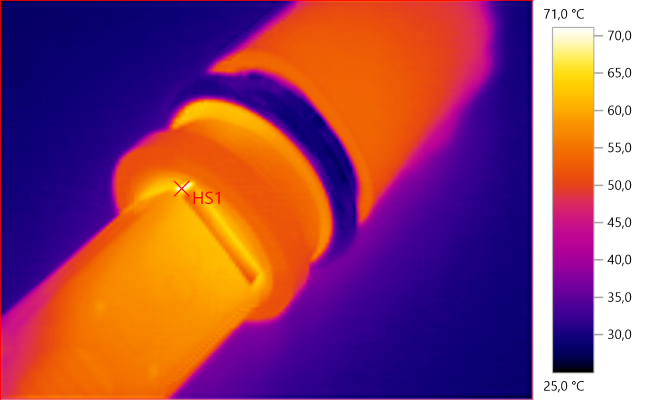
HS1: 71.0°C
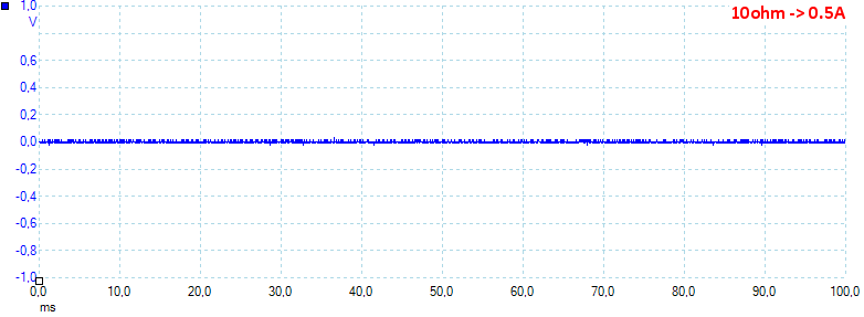
At 0.5A load the noise is 6mV rms and 69mVpp.
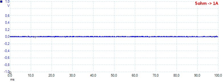
At 1A load the noise is 8mV rms and 106mVpp.
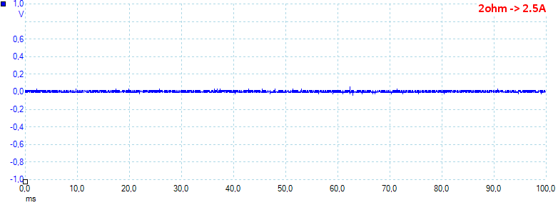
At 2.5A load the noise is 8mV rms and 106mVpp.
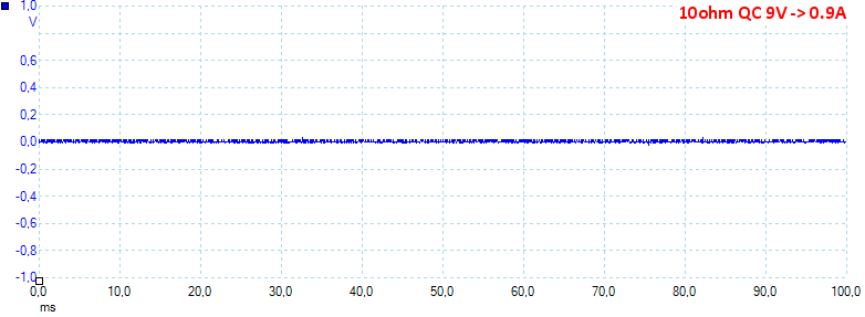
At 0.9A load the noise is 5mV rms and 60mVpp.
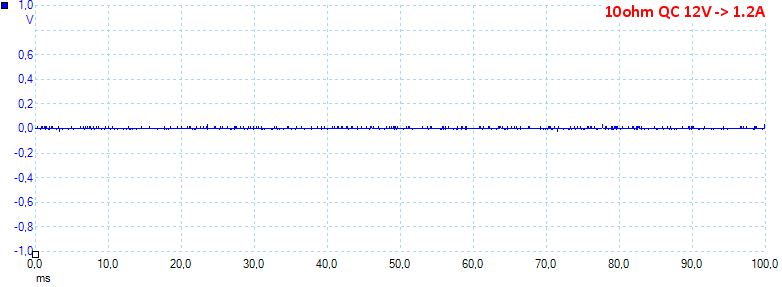
At 1.2A load the noise is 3mV rms and 79mVpp, all is very low values.
Tear down

Are there any reason to do a tear down with this nice rendering of the inside?
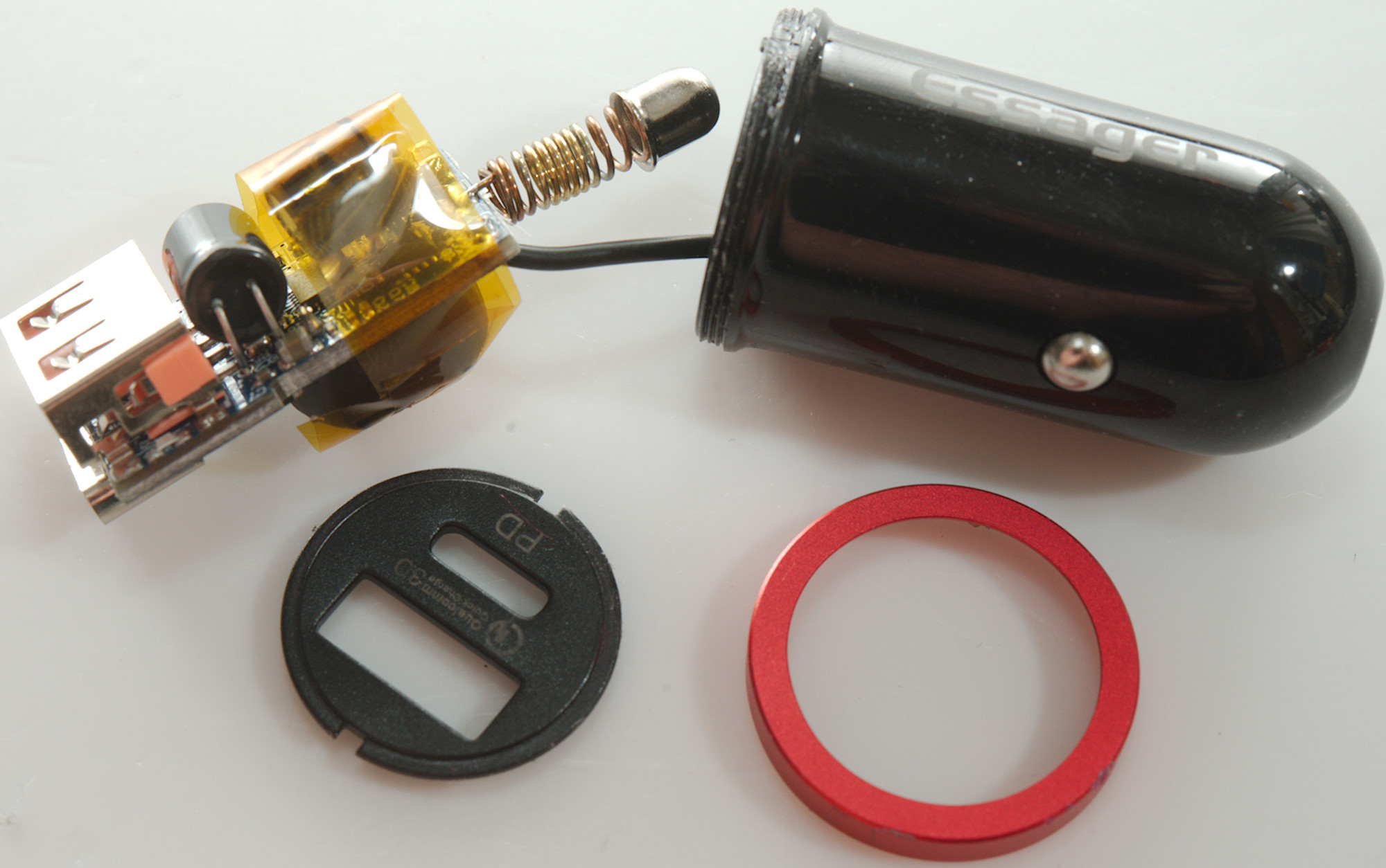
Looking below it can be seen that this rendering is fiction and has nothing to do with how the charger looks inside!
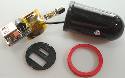
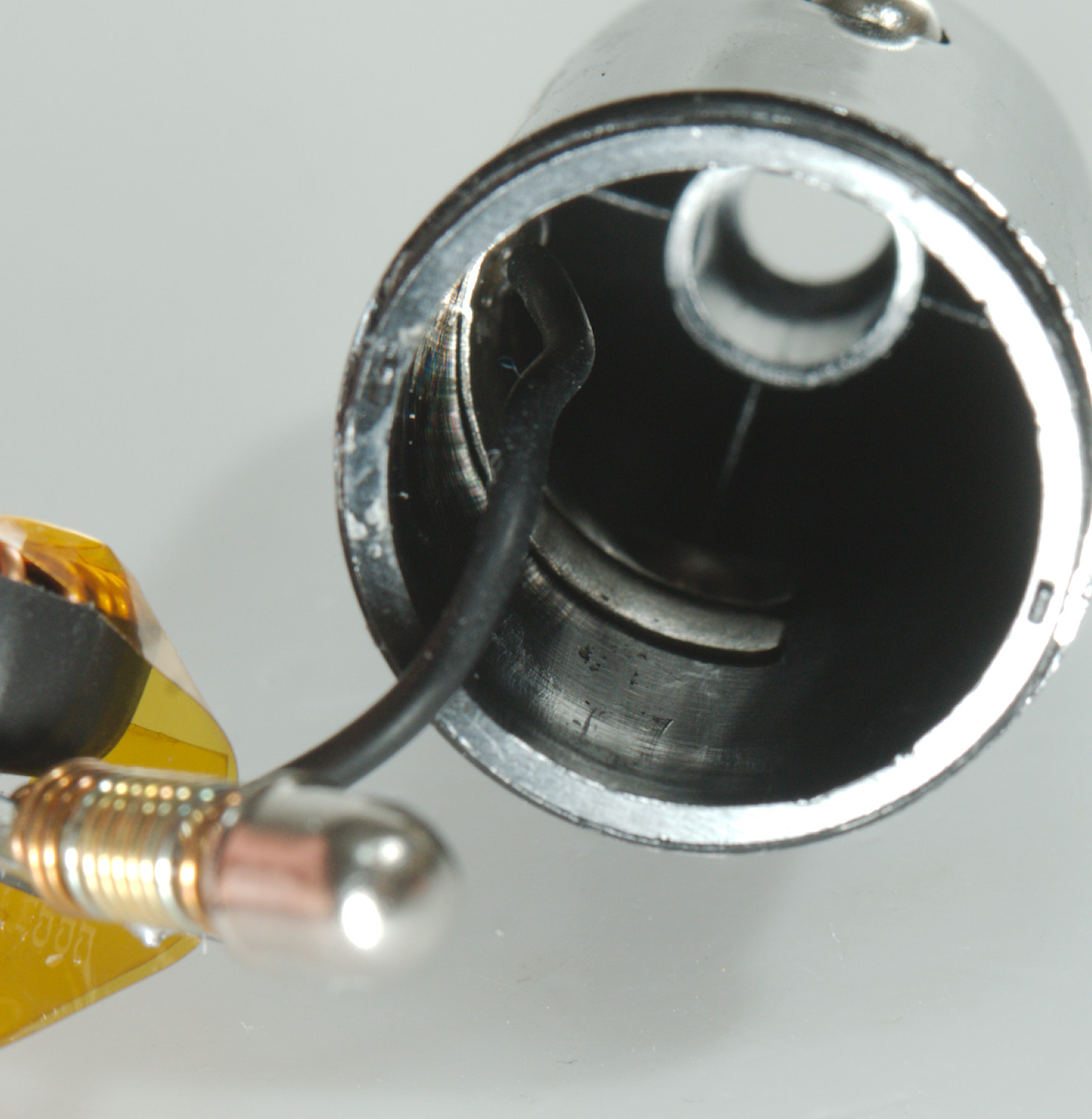
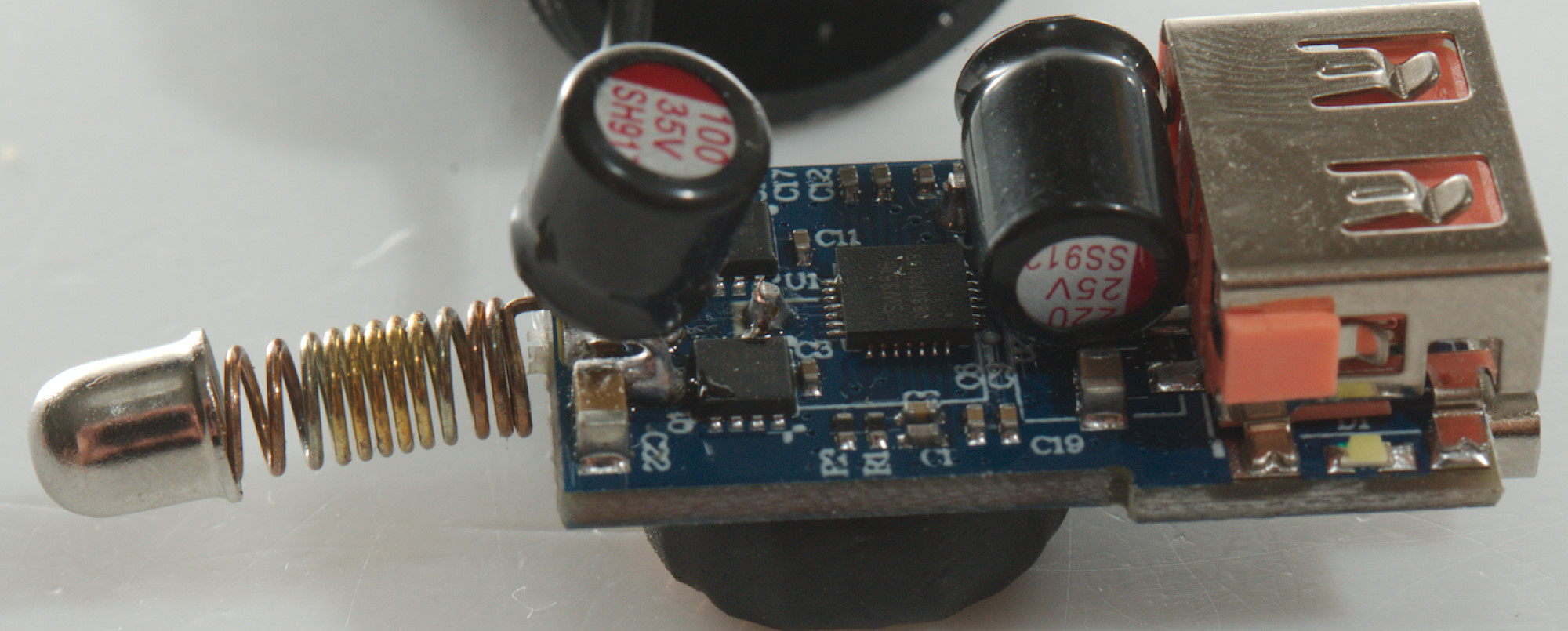
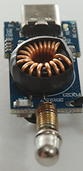
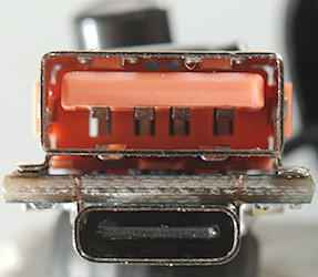
The front could be unscrewed, but not easily. The electronic could easily be pulled out.
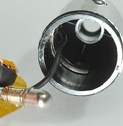
The wire goes to a ring with the two side connections.
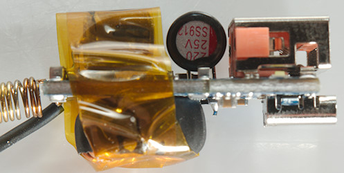
The electronic has kapton tape around it to isolate it from the metal ring.
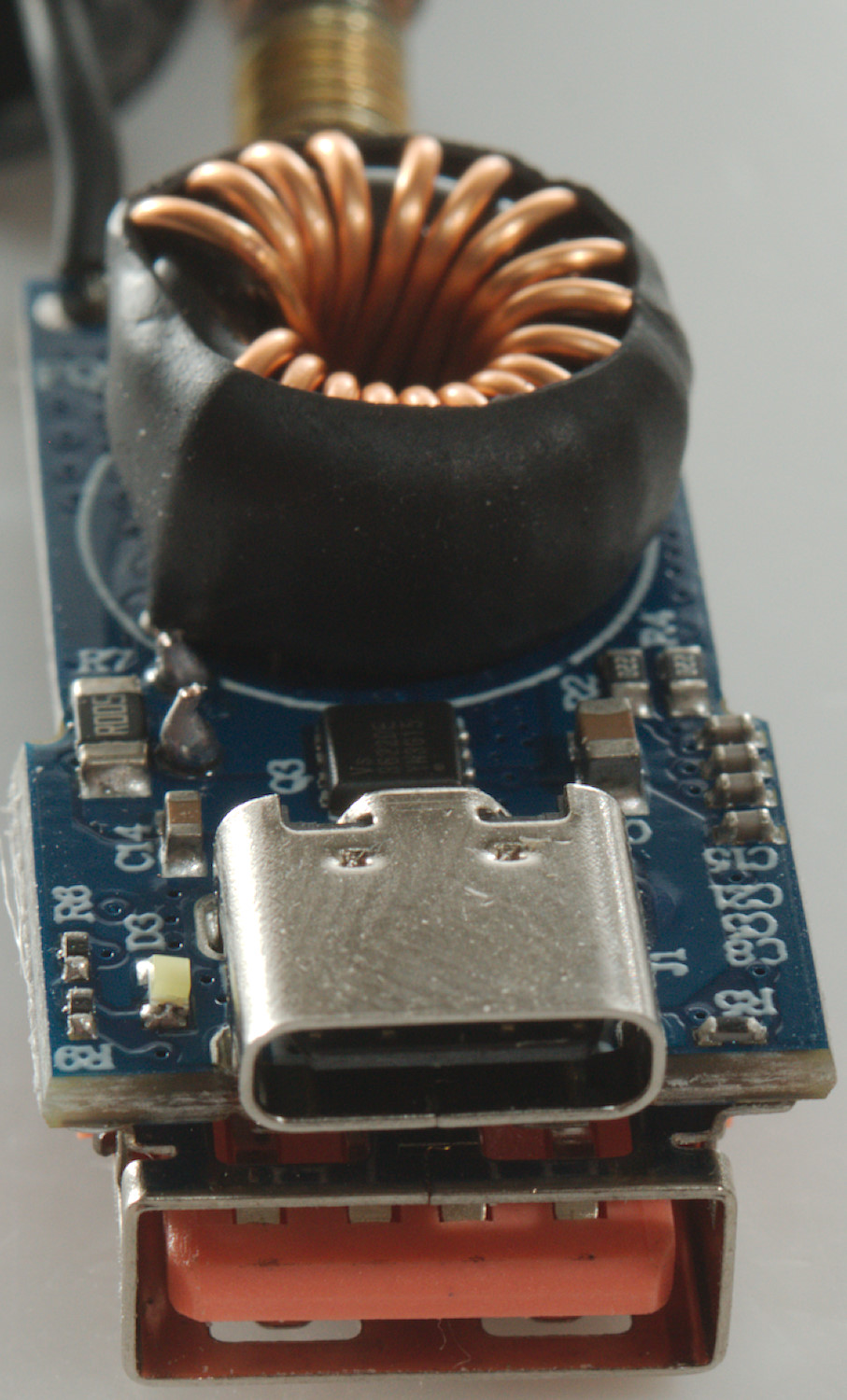
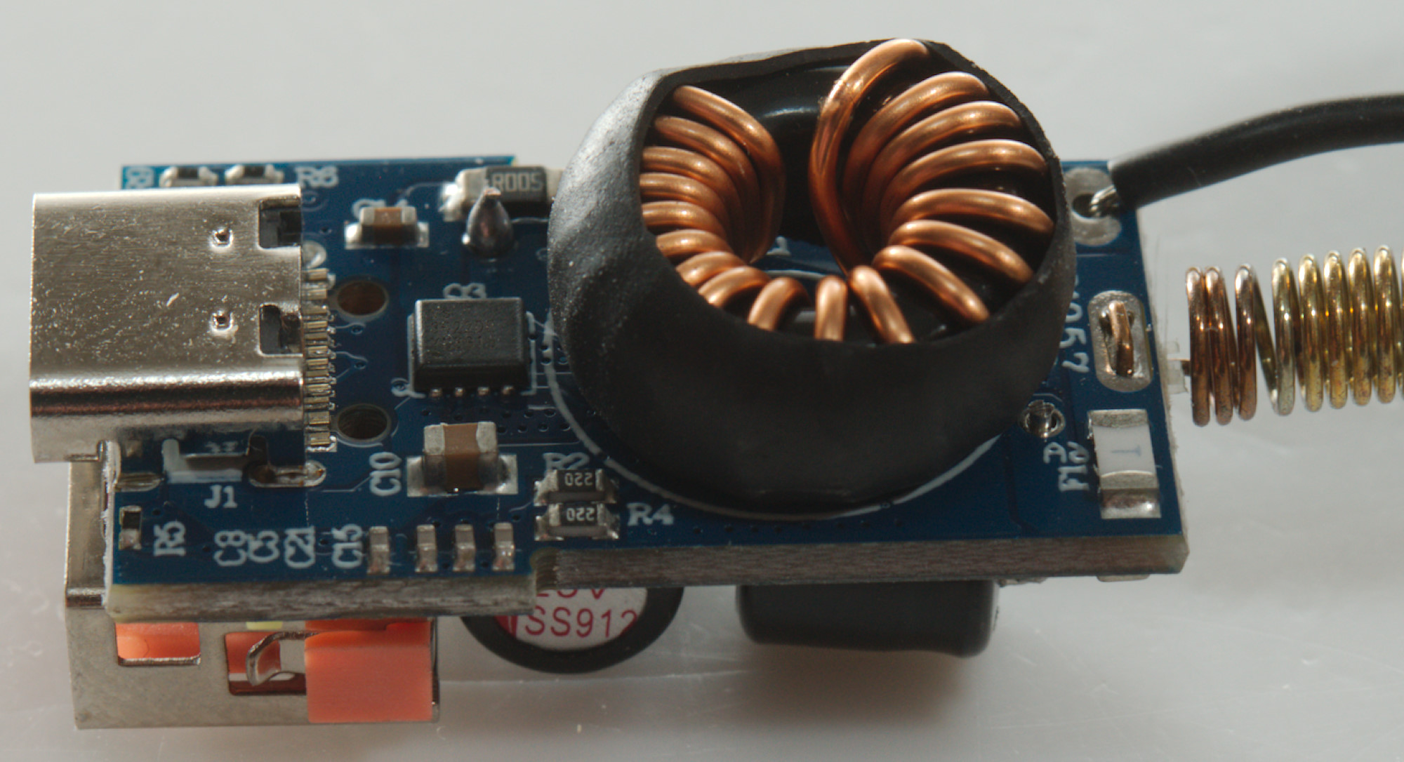
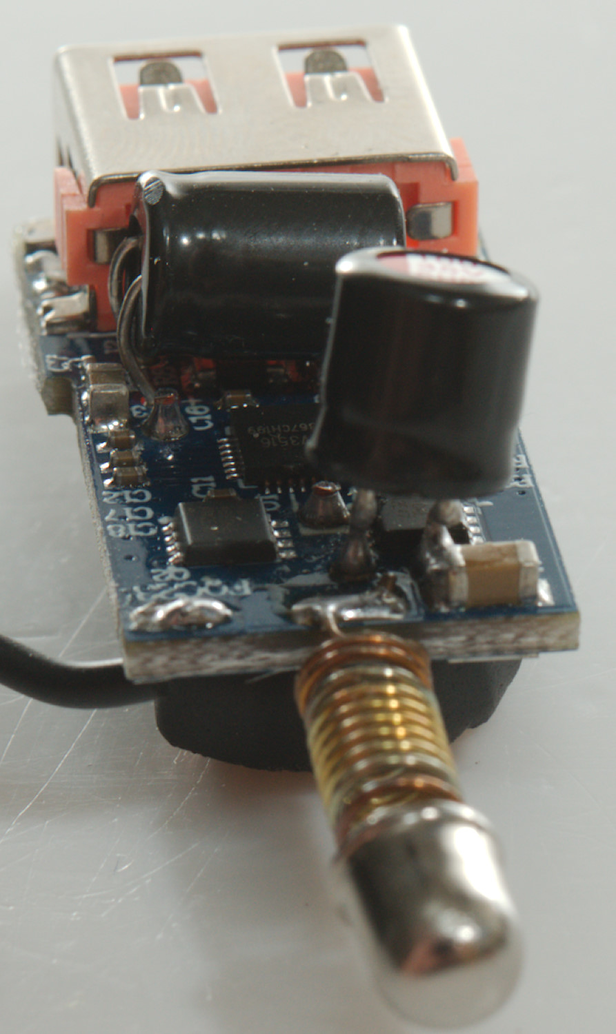
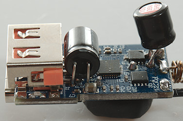
On this side is a input fuse (F1) and a dual transistor (Q3: VS3622DE) to switch the two outputs. There is also a current sense resistor (R7: 0.005ohm) and a led (D3).
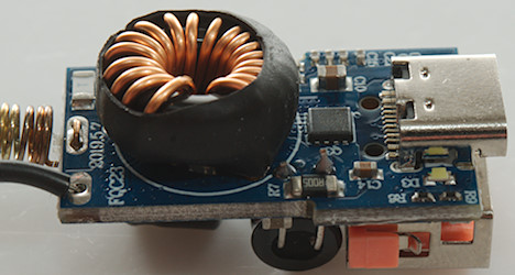
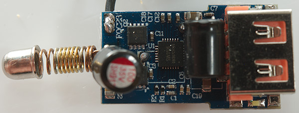
The two larger capacitor are bend across the electronic.
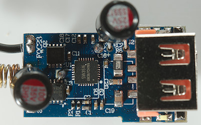
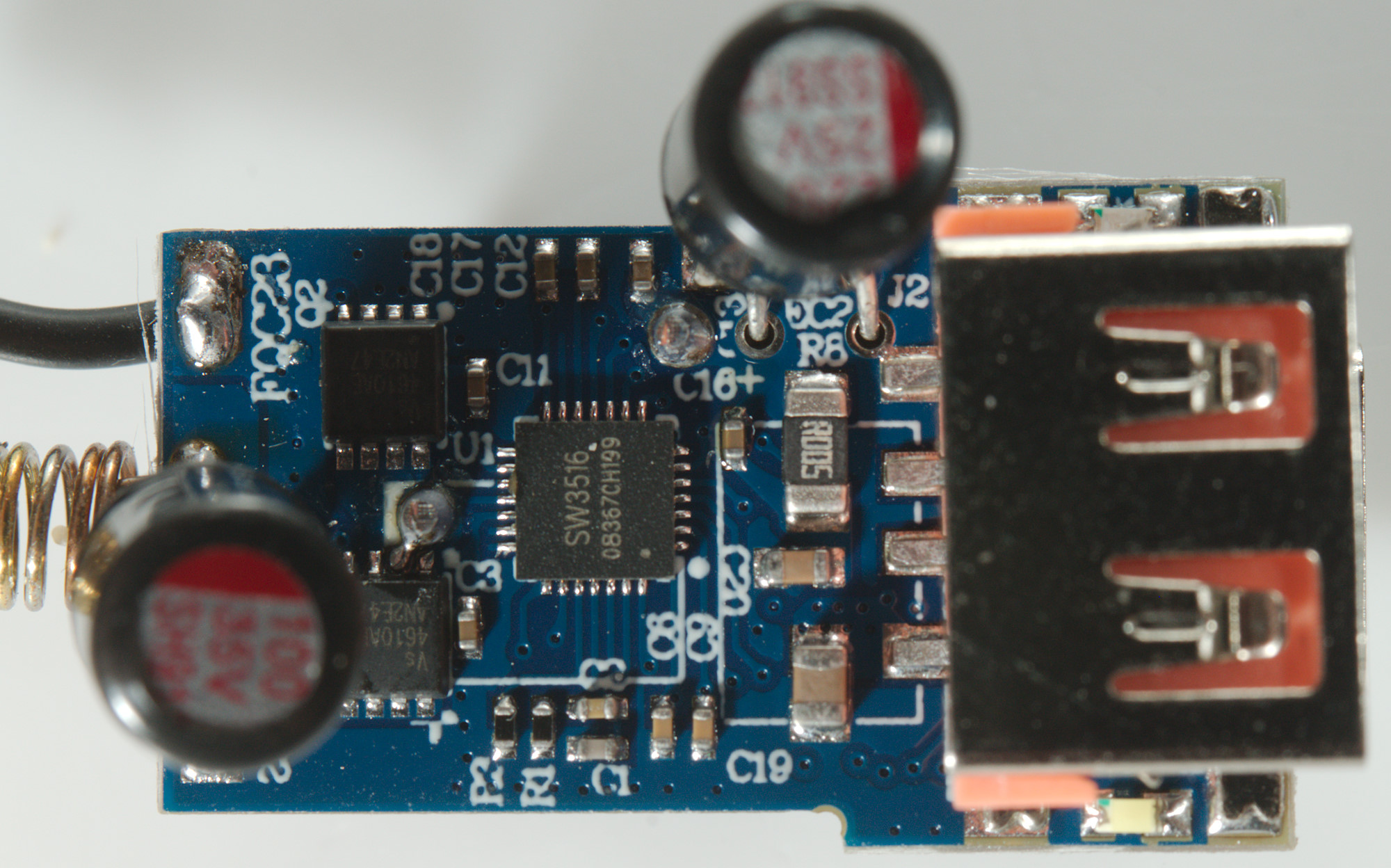
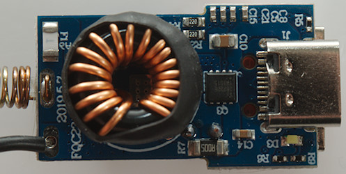
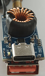
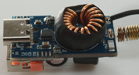
This side has the two switcher transistors (Q1 & Q2: VS4610) and a combined switcher and USB QC/PD controller (U1: SW3516) and also a current sense resistor (R8: 0.005ohm). There is two leds (D1 & D2) on this side.
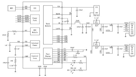
Typical schematic for the controller chip.


Conclusion
The charger works fine, but the specified 5A current is fiction, it it is a 3A or 2x2.4A charger and that is better for the connectors. Because it uses a single switcher it is very restricted when trying to charge two devices, it will only supply 5V and do not like using advanced protocols.
It is a good car charger, but works best when charging a single device at a time.
Notes
Read more about how I test USB power supplies/charger
Compare car chargers and other DC supplied chargers