Flowme 2 port with LED display HKL-USB36
Official specifications:
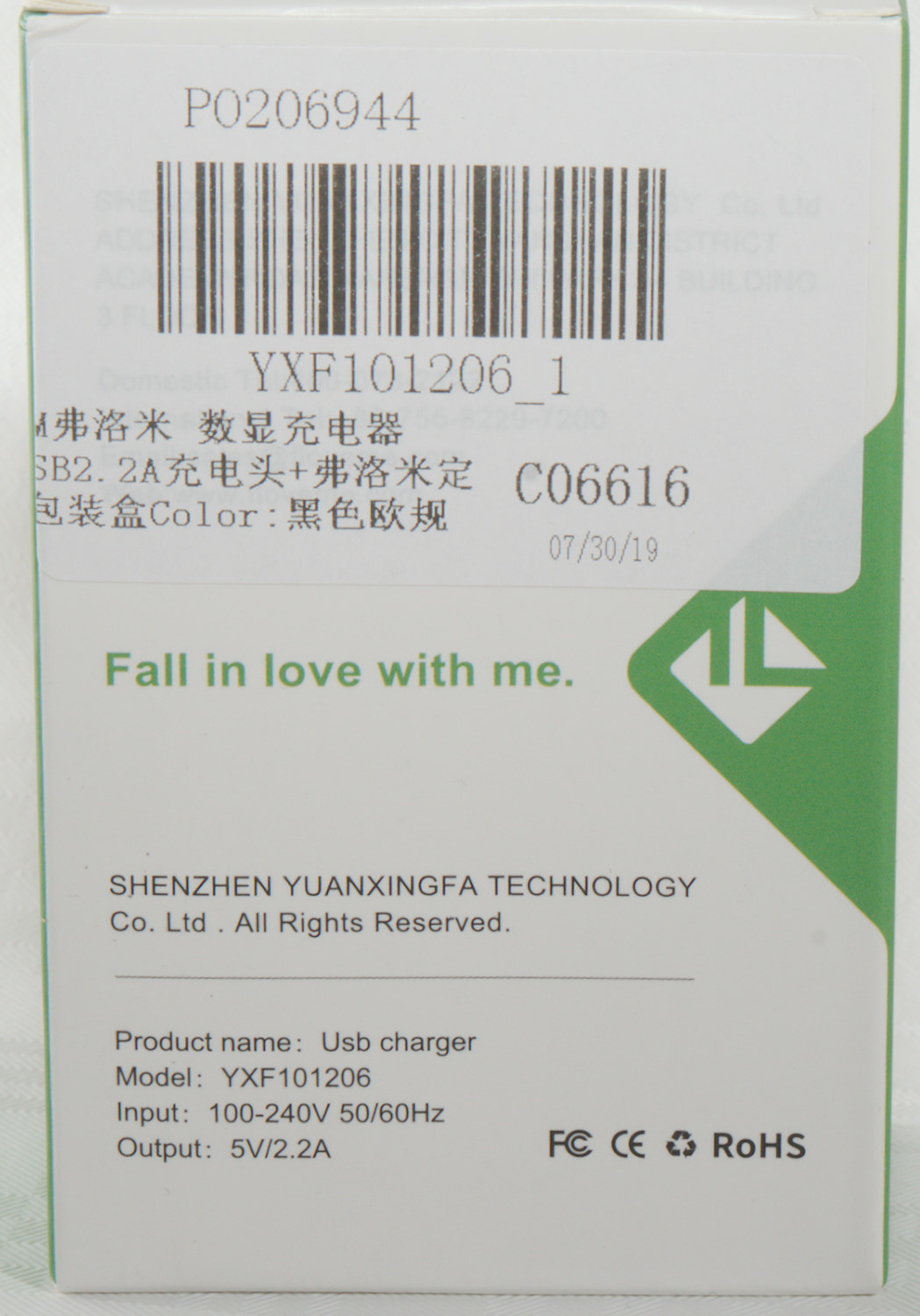
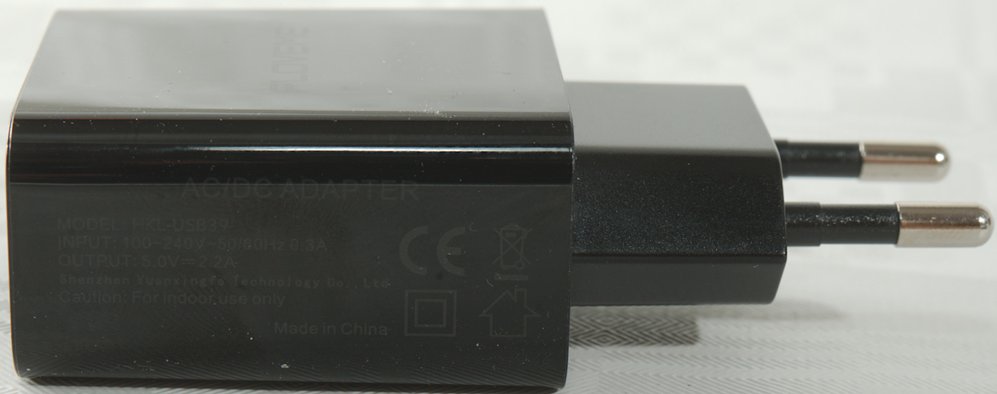
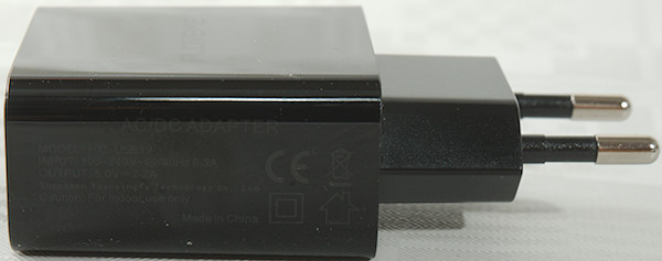
- Input: AC 100-240V
- Output: 5V 2.2A
- Net Weight: 55g
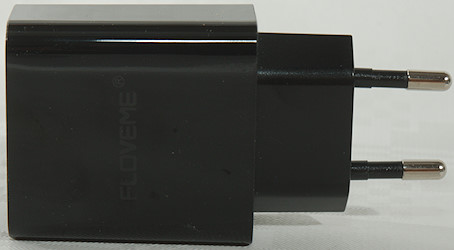
I got it from Aliexpress: FLOVEME Official Flagship Store

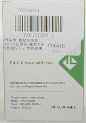
I got it in a cardboard box with some specifications on it.
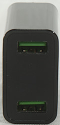
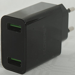
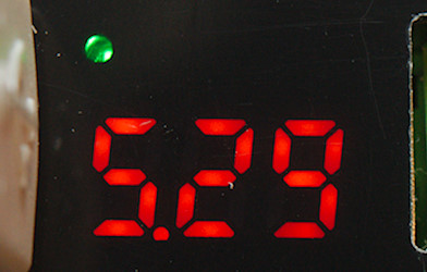
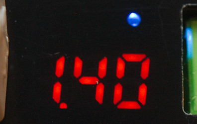
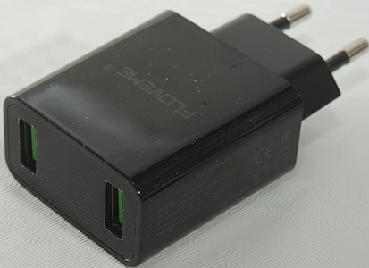
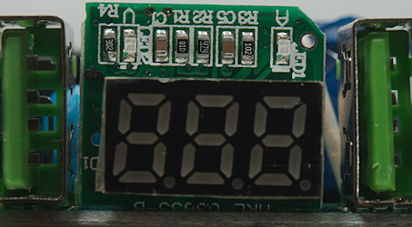
The charger has a display that shows voltage and current, the led color indicates which on. Current will only be indicated when there is a current draw and the display turns off while charger is idle.
Measurements
- Power consumption when idle is 0.08 Watt.
- USB output is auto coding with Apple 2.4A, Samsung, DCP
- USB outputs are in parallel.
- Voltage display is within 0.01V.
- Display turns on at 0.2A and off when below 0.07A for 10 seconds.
- The current is combined for both outputs.
- Blue led indicate current, green led voltage display.
- Weight: 48g
- Size: 82.1 x 42.5 x 24.2 mm
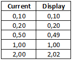
The current display has good precision.

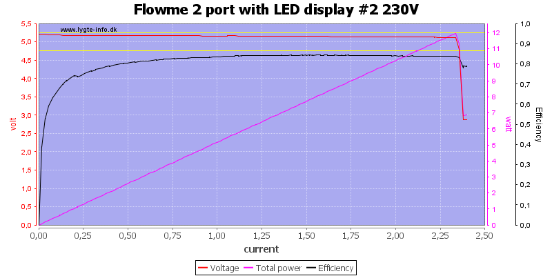
One output can deliver about 2.3A and the current measurement is before the voltage feedback, preventing voltage drop at high current.
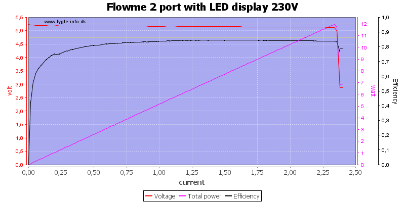
The other output is the same 2.3A
And together it is also 2.3A
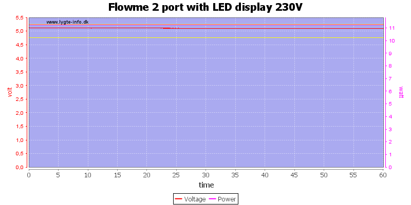
Running one hour with 2.2A was no problem.
The temperature photos below are taken between 30 minutes and 60 minutes into the one hour test.
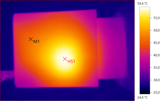
M1: 46.5°C, HS1: 59.4°C
HS1 is the transformer
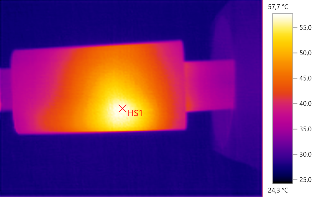
HS1: 57.7°C
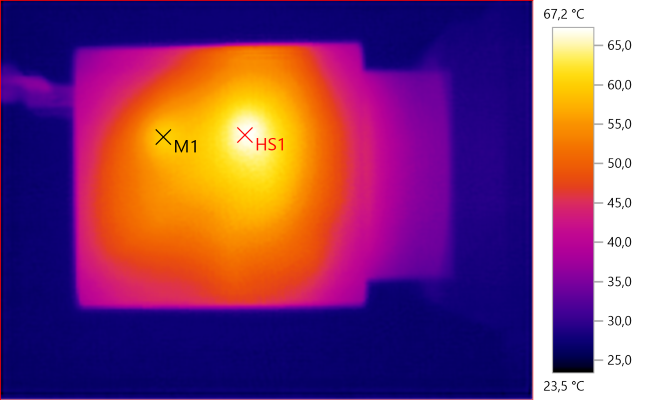
M1: 59.8°C, HS1: 67.2°C
M1 is the transformer and M1 is the rectifier chip.
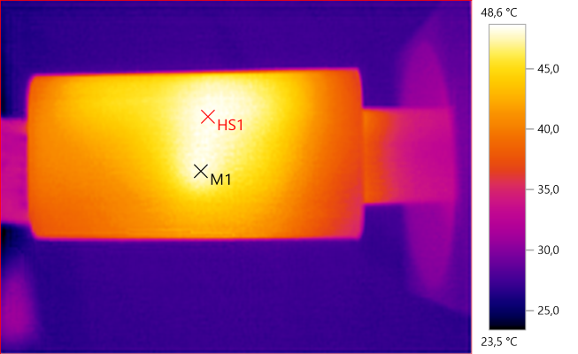
M1: 48.1°C, HS1: 48.6°C
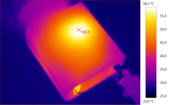
M1: 55.4°C, HS1: 58.3°C
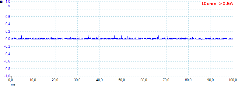
At 0.5A the noise is 8mV rms and 143mVpp.
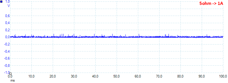
At 1A the noise is 10mV rms and 126mVpp.
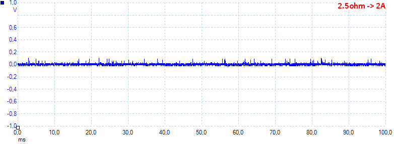
At 2A the noise is 15mV rms and 163mVpp, all noise looks fairly low.
Tear down
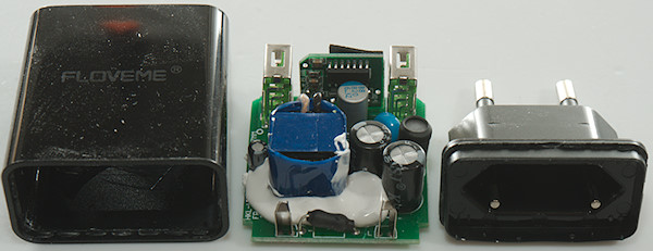
Mounting the plug in my vice and hitting the body of the charger with my mallet broke it open.
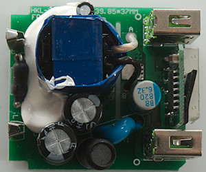
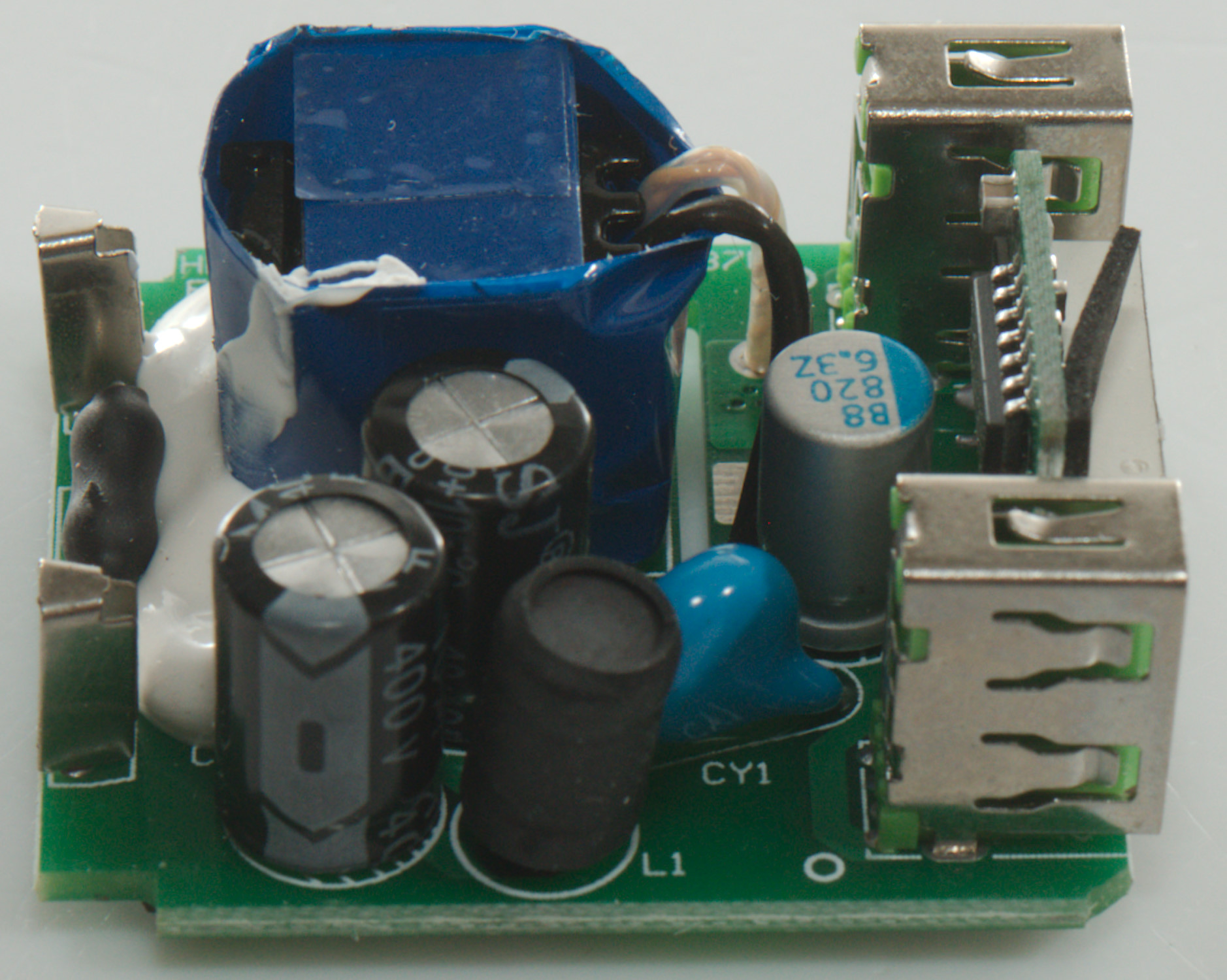
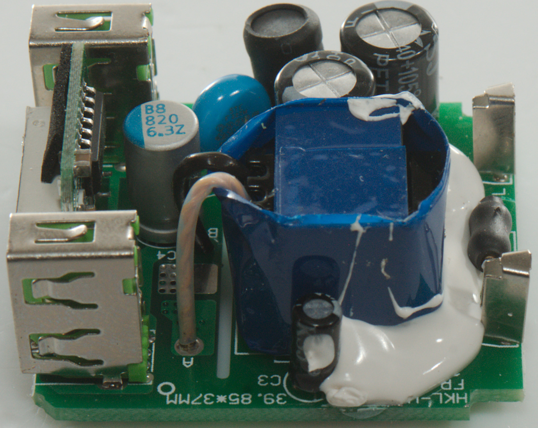
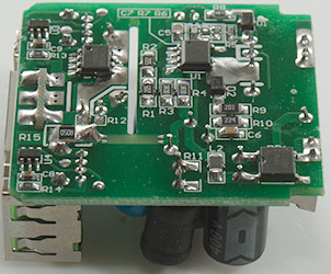
At the mains input is a fuse or fusible resistor. There is two smoothing capacitors (C1 & C2) with a inductor (L1) between. There is a blue safety capacitor (CY1). The low volt side has a small circuit board for the volt and am meter.


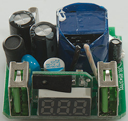

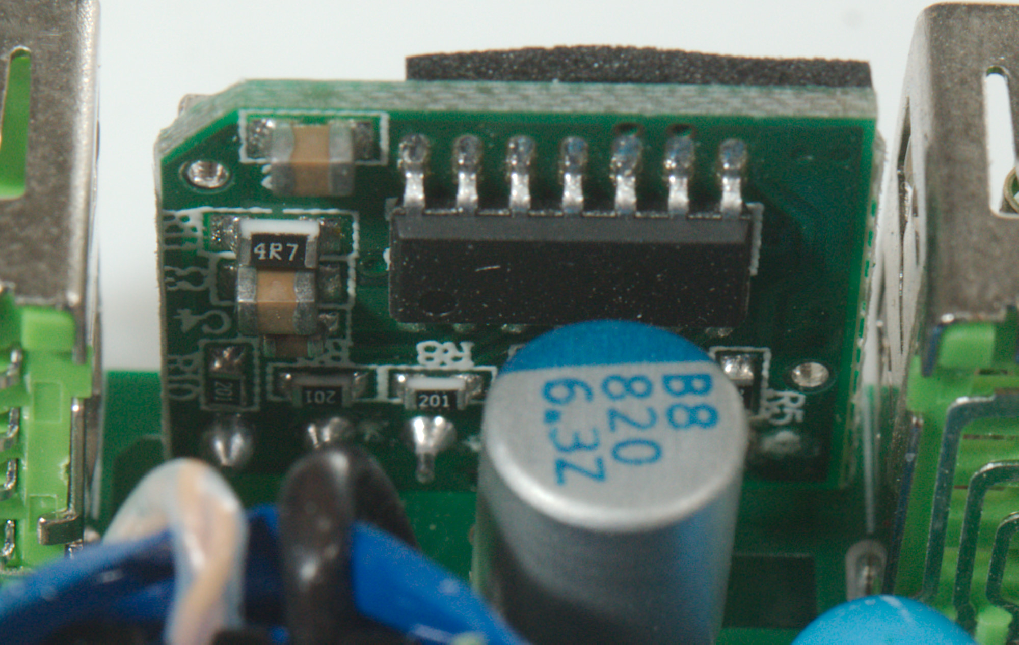
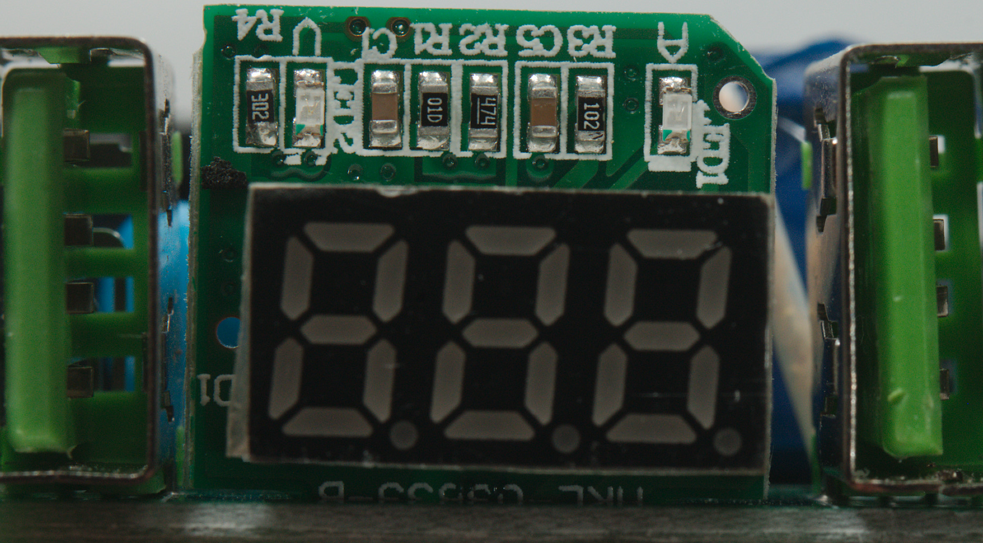
The volt and am meter circuit board has a couple of resistors and capacitors, together with a single unmarked chip.
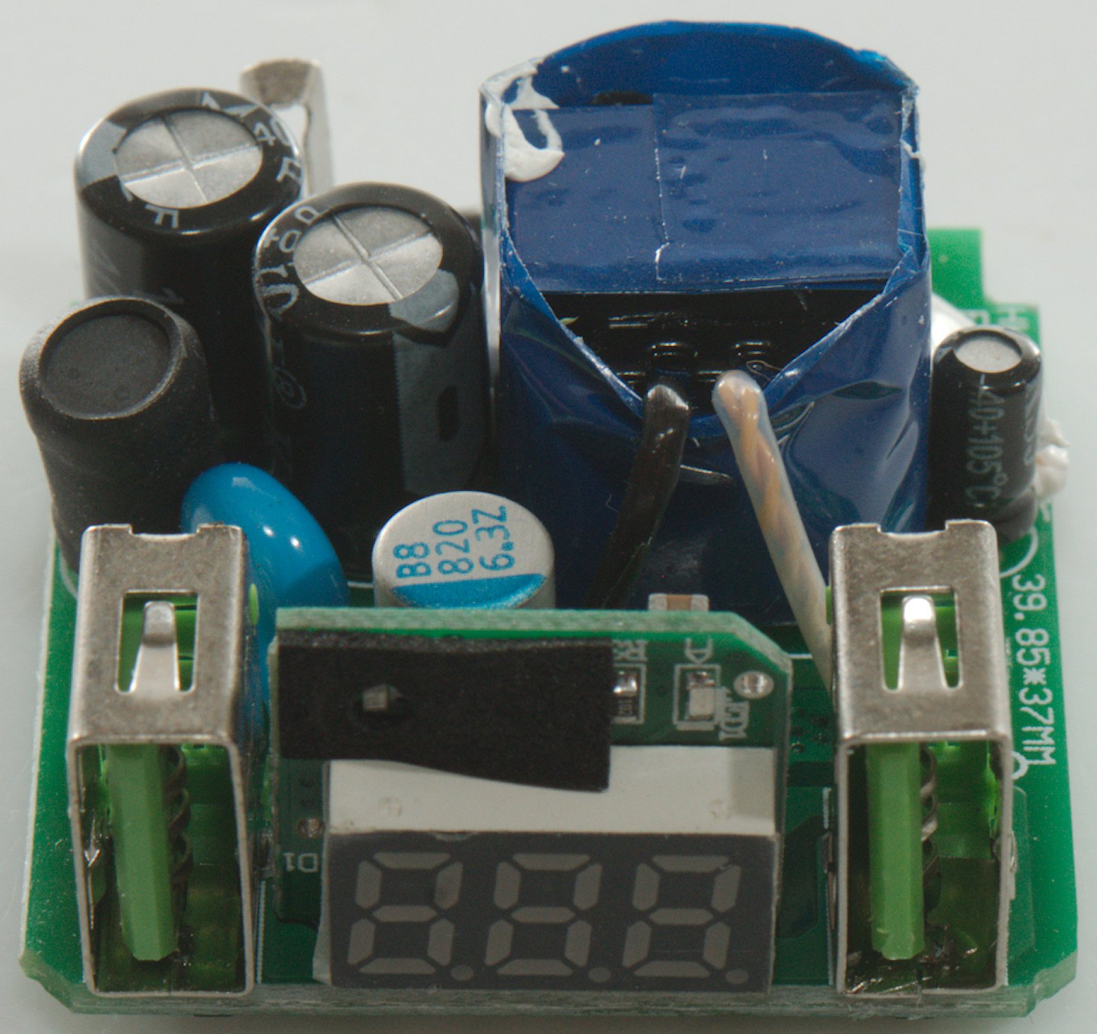
This side has mode capacitors and resistors, the display and the two leds.
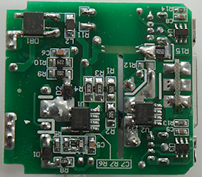
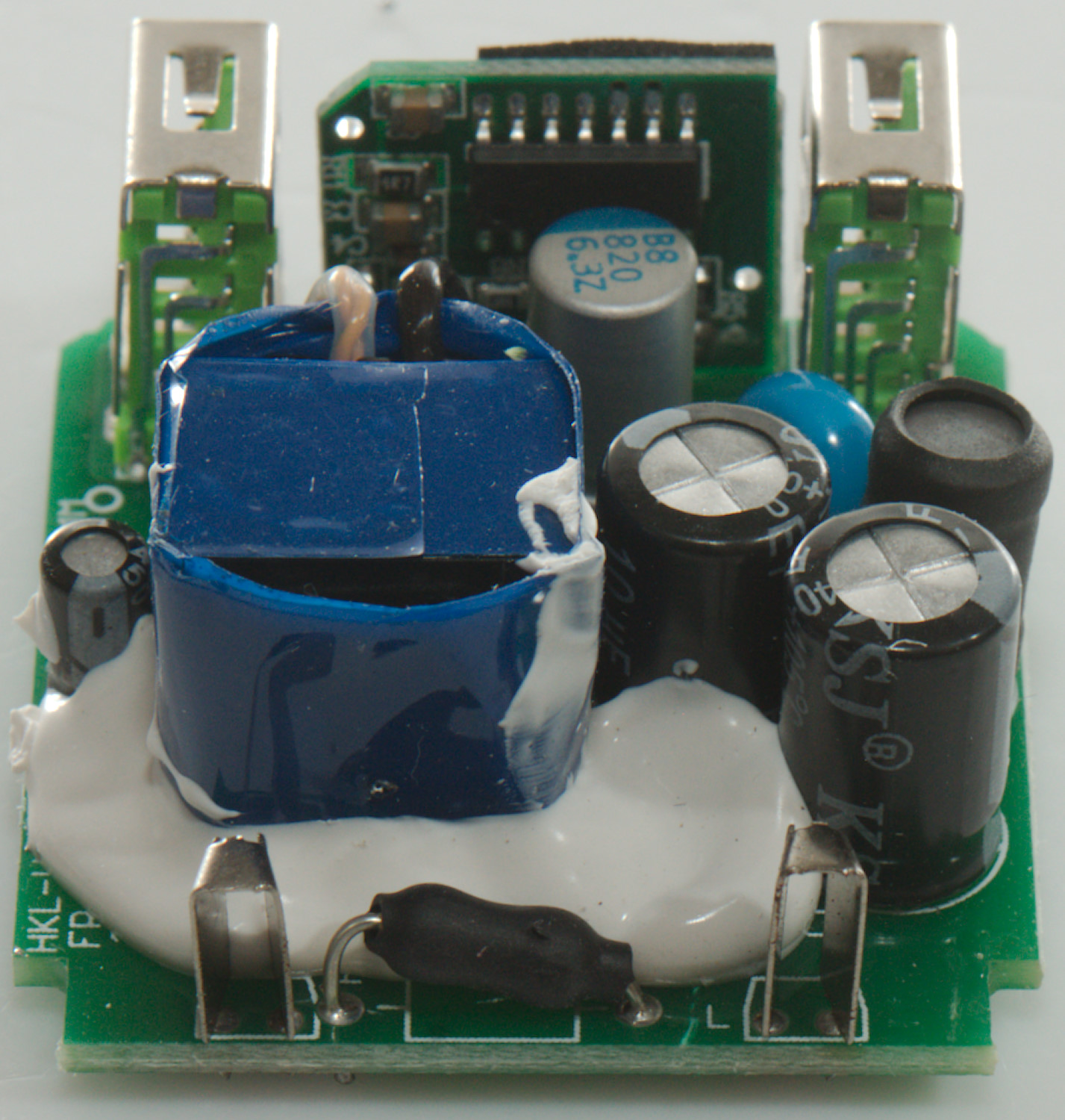
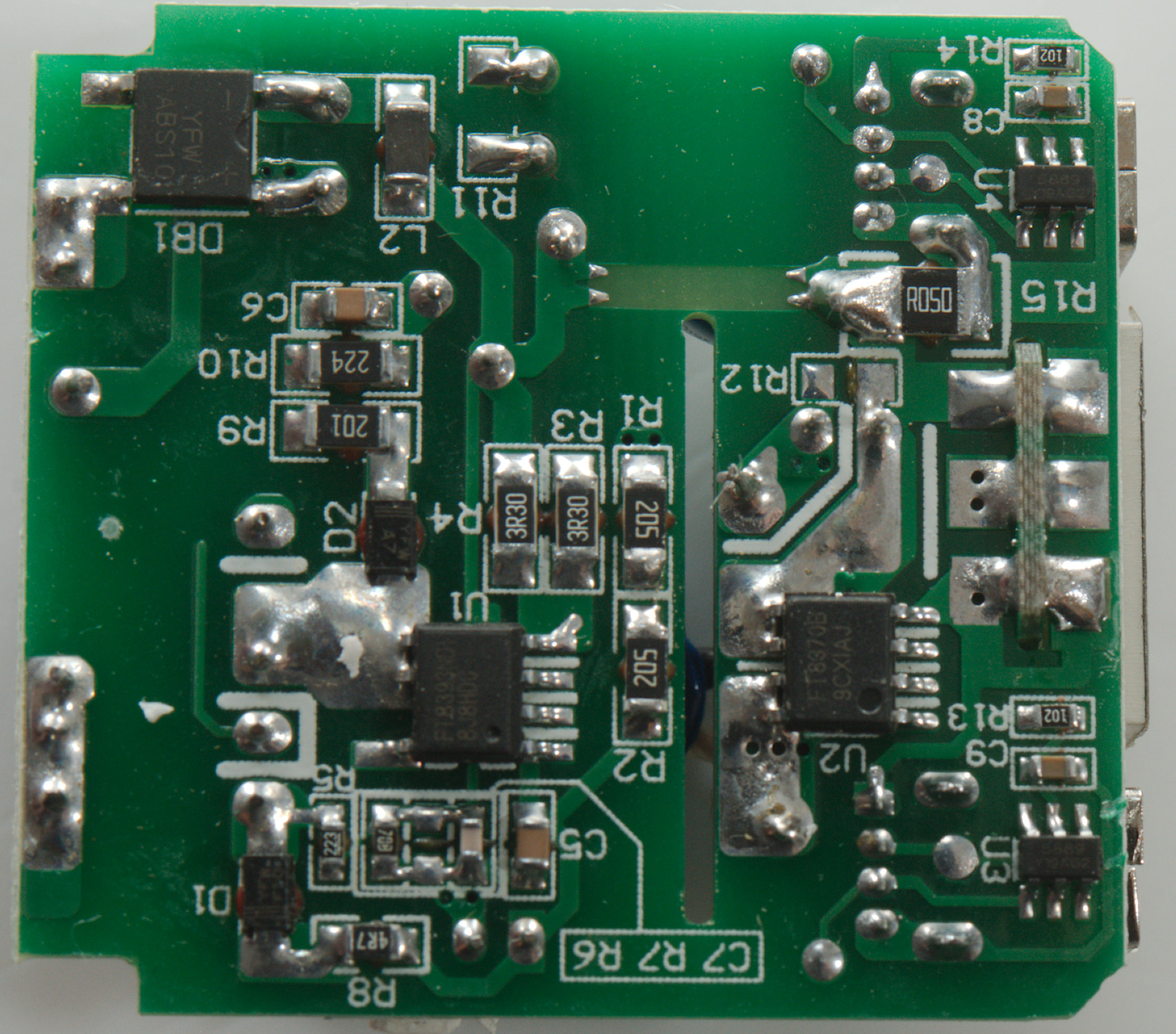
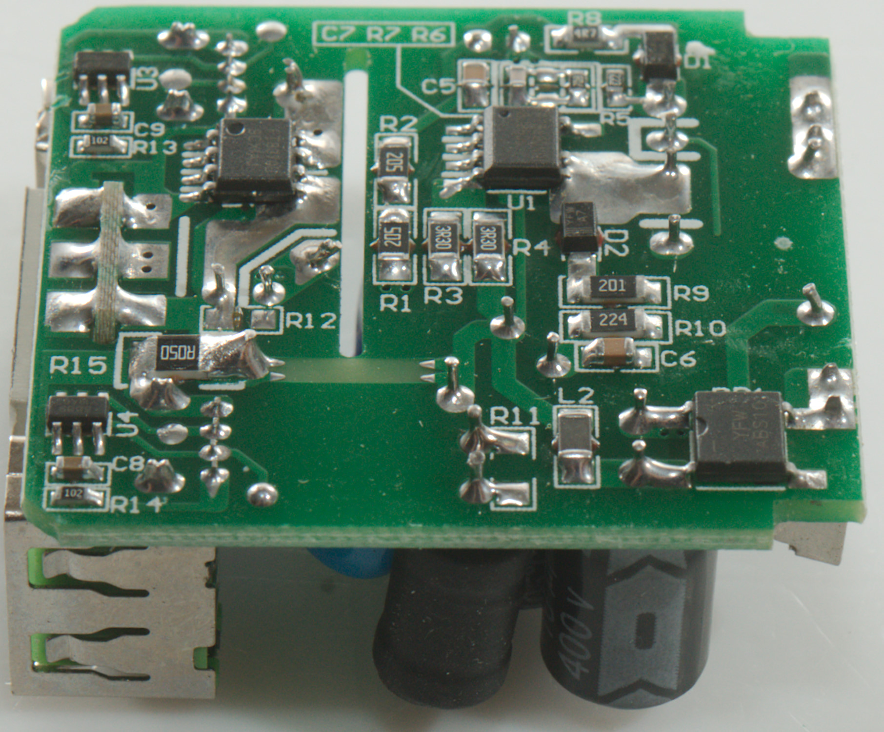
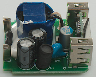
On this side is the bridge rectifier (BD1), the mains switcher (U1: FT8393ND1) and a synchronous rectifier (U2: FT8370B 5V/2.4A). There is a current sense resistor (R15: 50mOhm) and two auto coding chips (U3 & U4: MA5889)
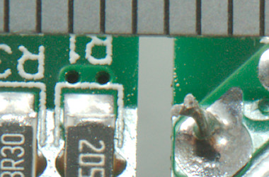
Distance between mains and low volt side must be 4mm when there is a air gap, here it is 1mm. A piece of plastic through the gab would have fixed this.
Testing with 2830 volt and 4242 volt between mains and low volt side, did not show any safety problems.
Conclusion
The charger works fine, but the output power is rather low for two outputs, it would have been acceptable for one output. Generally the charger looks good, but it has a safety problem, I wonder if the missing piece of plastic protection is a production fault on my copy.
Notes
Index of all tested USB power supplies/chargers
Read more about how I test USB power supplies/charger
How does a usb charger work?