GUSGU Dual USB Charger LED Display LQ-008
Official specifications:
- Model No.: GUSGU DUAL USB LED Charger
- Input: AC 100-204V ~ 50-60Hz 0.4A
- Total output: 5V/ 2.4A
- Single port output: 5V/2.4A(Max.)
- Material: fireproof PC
- Weight: 57g
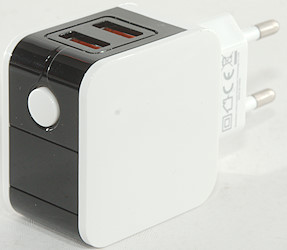
- Dimension: 80x45x28mm
I got it from aliexpress dealer GUSGU BrandFlagship Store
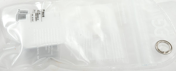
I got it in a plastic bag with some text on that has nothing with the charger to do.
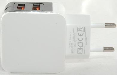
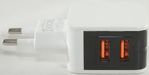
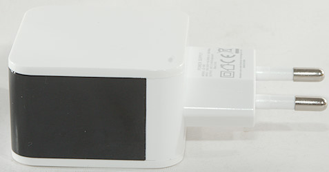
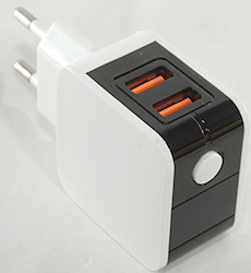
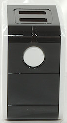
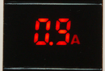
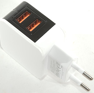
The charger has a display showing voltage and current for both usb output together, the button is used to change between current and voltage. It will also change automatic at the start of a charge. Display will only turn on during charging.
Measurements
- Power consumption when idle is 0.1 watt
- Display turns on at around 0.15A
- Both USB output is auto coding with Apple 2.4A and DCP
- The two outputs are in parallel.
- Weight: 53.2g
- Size: 82.2 x 45 x 28.7mm
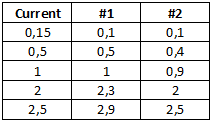
The meter do not show the same current for the two outputs.
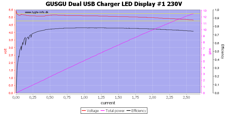
The output can deliver about 2.5A, this matches fine with a 2.4A rated charger.

The other output port is the same.
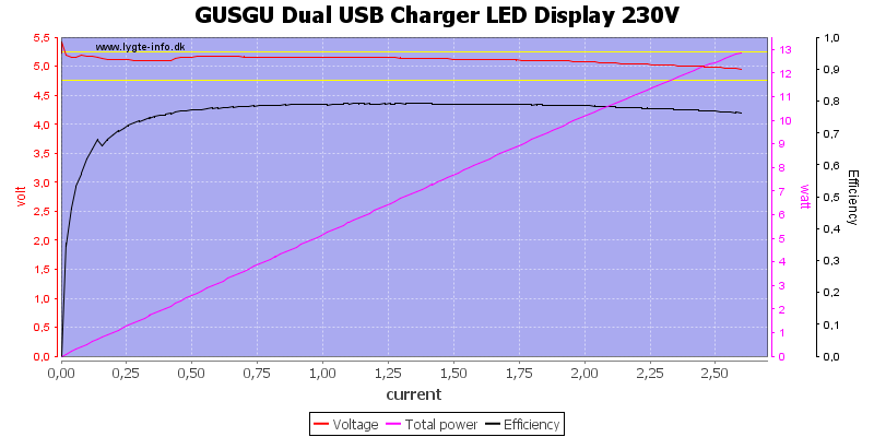
And both ports at the same time is also the same.

Also at 120VAC
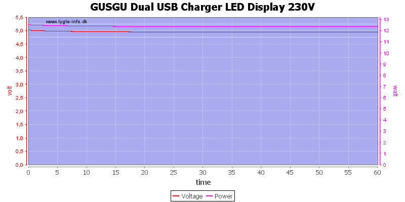
Running 1 hour at 2.5A worked fine.
The temperature photos below are taken between 30 minutes and 60 minutes into the one hour test.
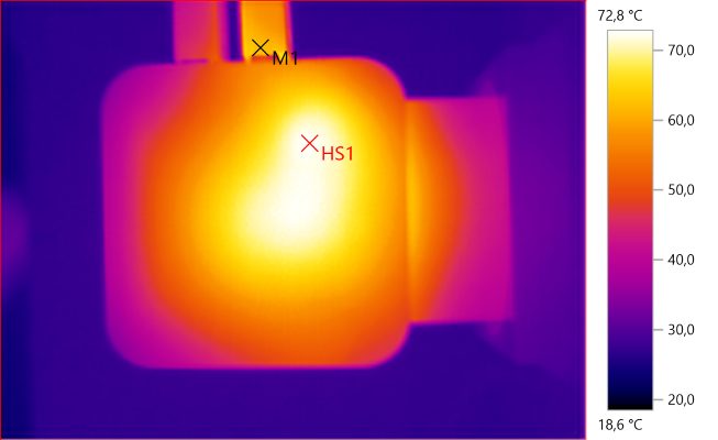
M1: 62.3°C, HS1: 72.8°C
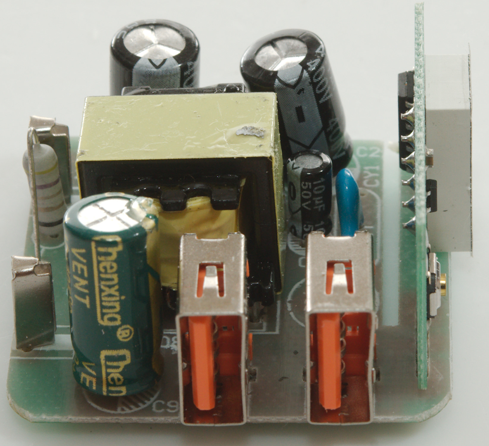
HS1 is the output capacitor and the transformer is next to it.
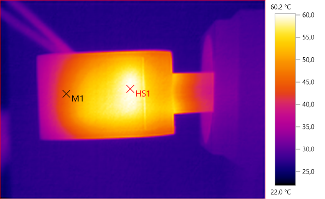
M1: 45.8°C, HS1: 60.2°C
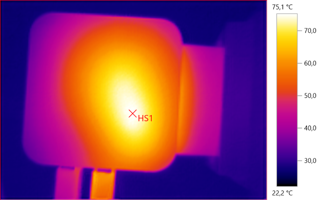
HS1: 75.1°C
HS1 is the transformer.
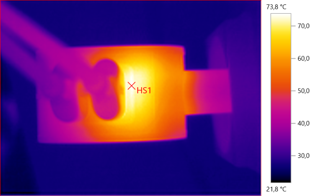
HS1: 73.8°C
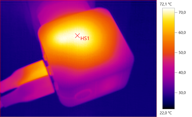
HS1: 72.1°C
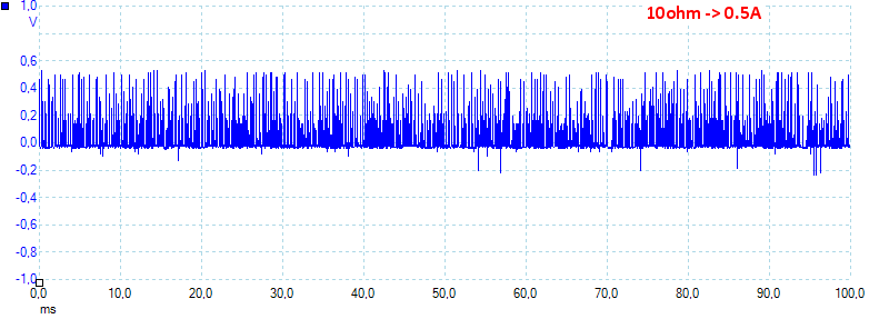
At 0.5A the noise is 93mV rms and 979mVpp.
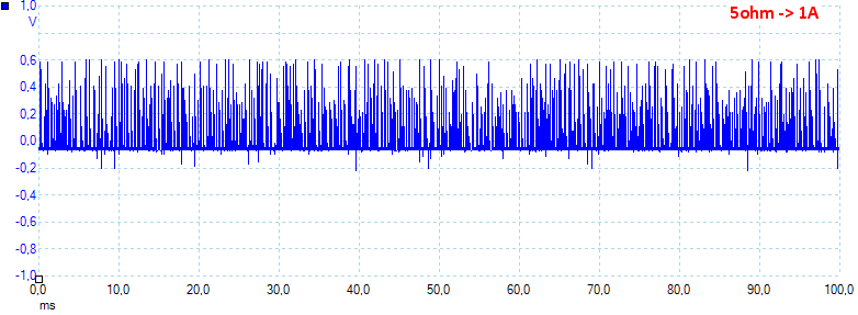
At 1A the noise is 130mV rms and 953mVpp.
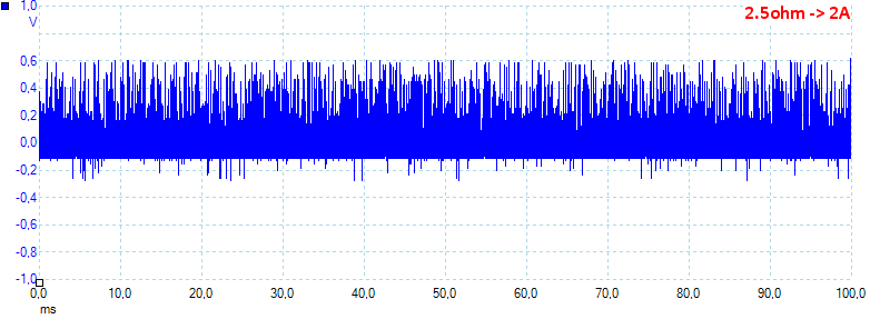
At 2A the noise is 172mV rms and 1068mVpp.
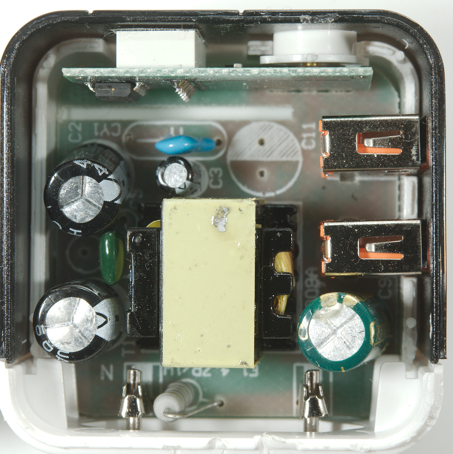
Tear down
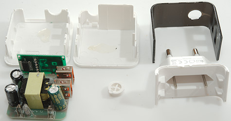
I mounted it my vice and gave it a few whacks with my mallet, that broke the glue and then I could break it apart.
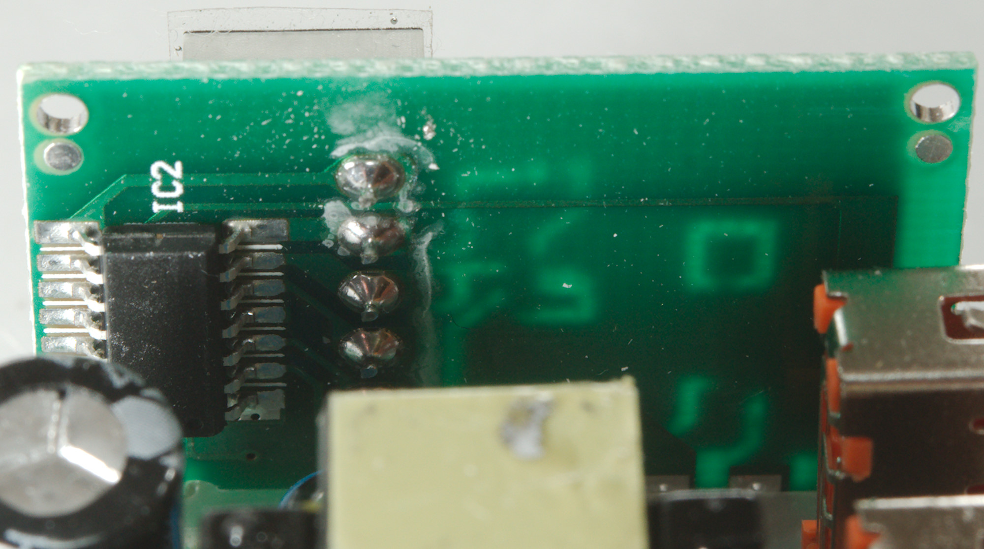
Circuit board in box, when put together there is a pice of white plastic behind the display board.
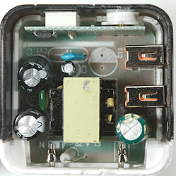
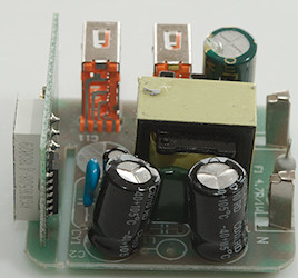
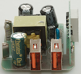
On this side is the input fuse (F1: 4.7ohm/1W fusible resistor), a "blue safety capacitor" (CY1) that is not a safety capacitor.
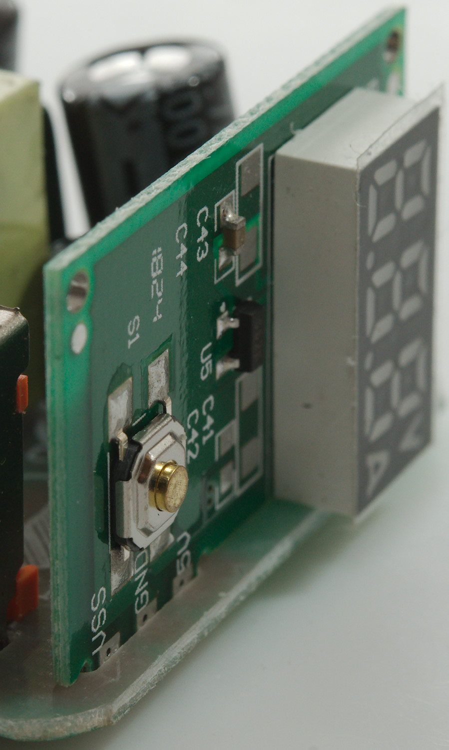
This display board is also mounted on this side.
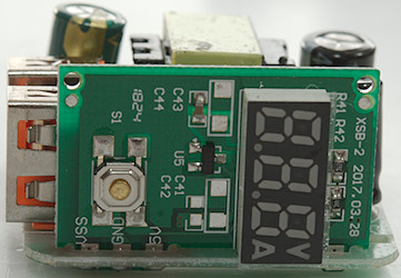
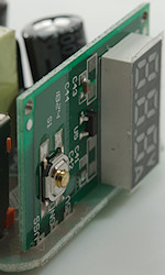
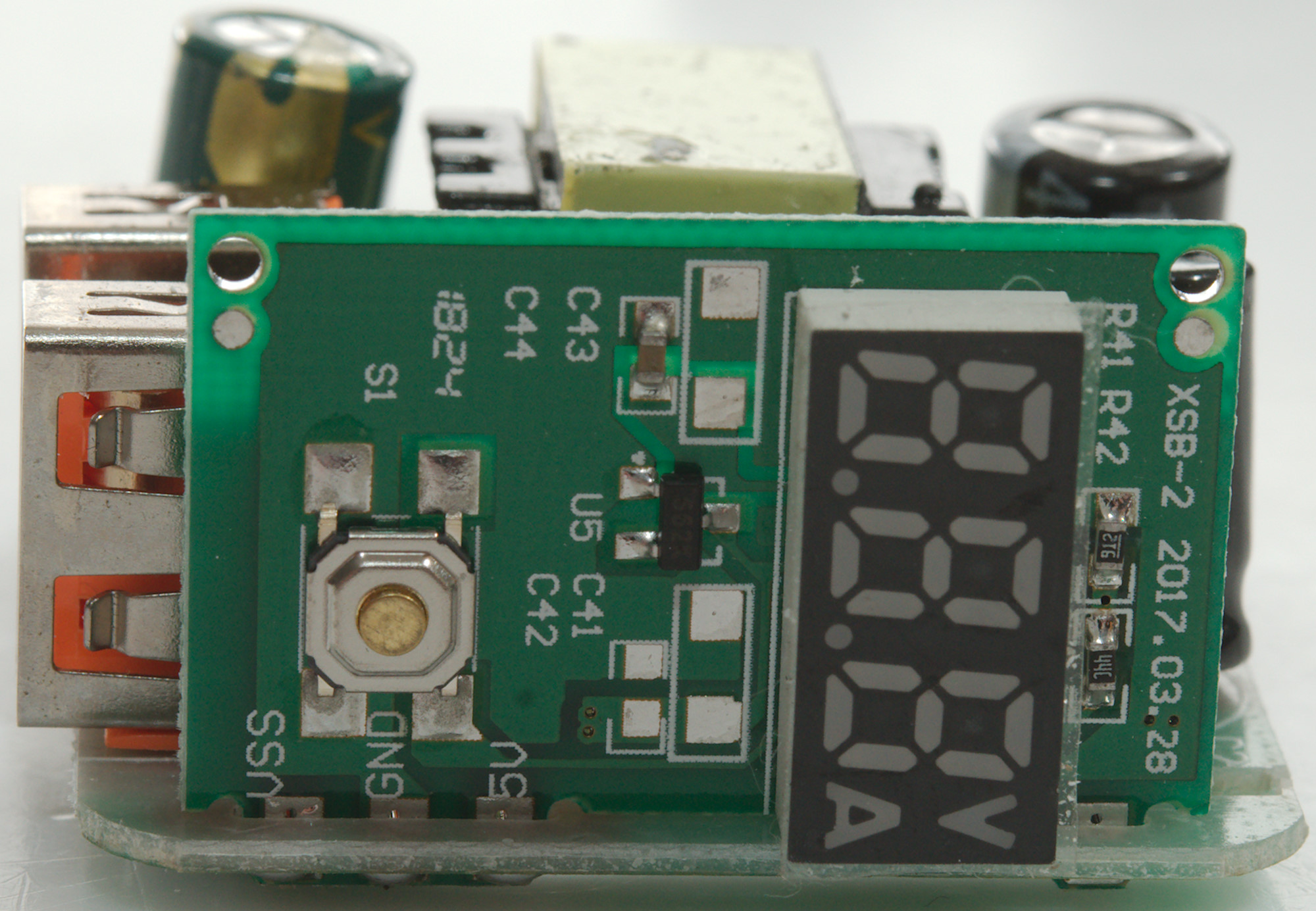
On this side of the display board if the display, a switch and probably a 3.3V voltage regulator (U5: 662K: XC6206)

On the backside is the voltmeter chip.
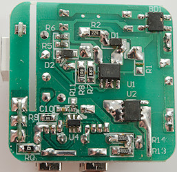
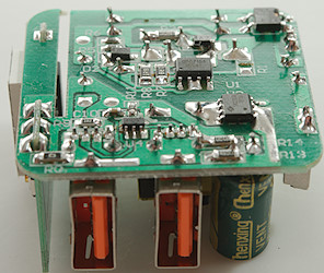
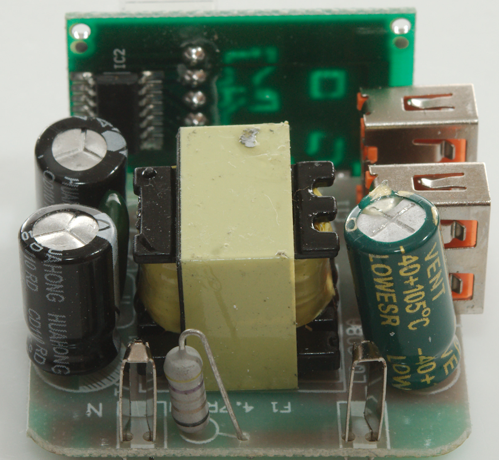
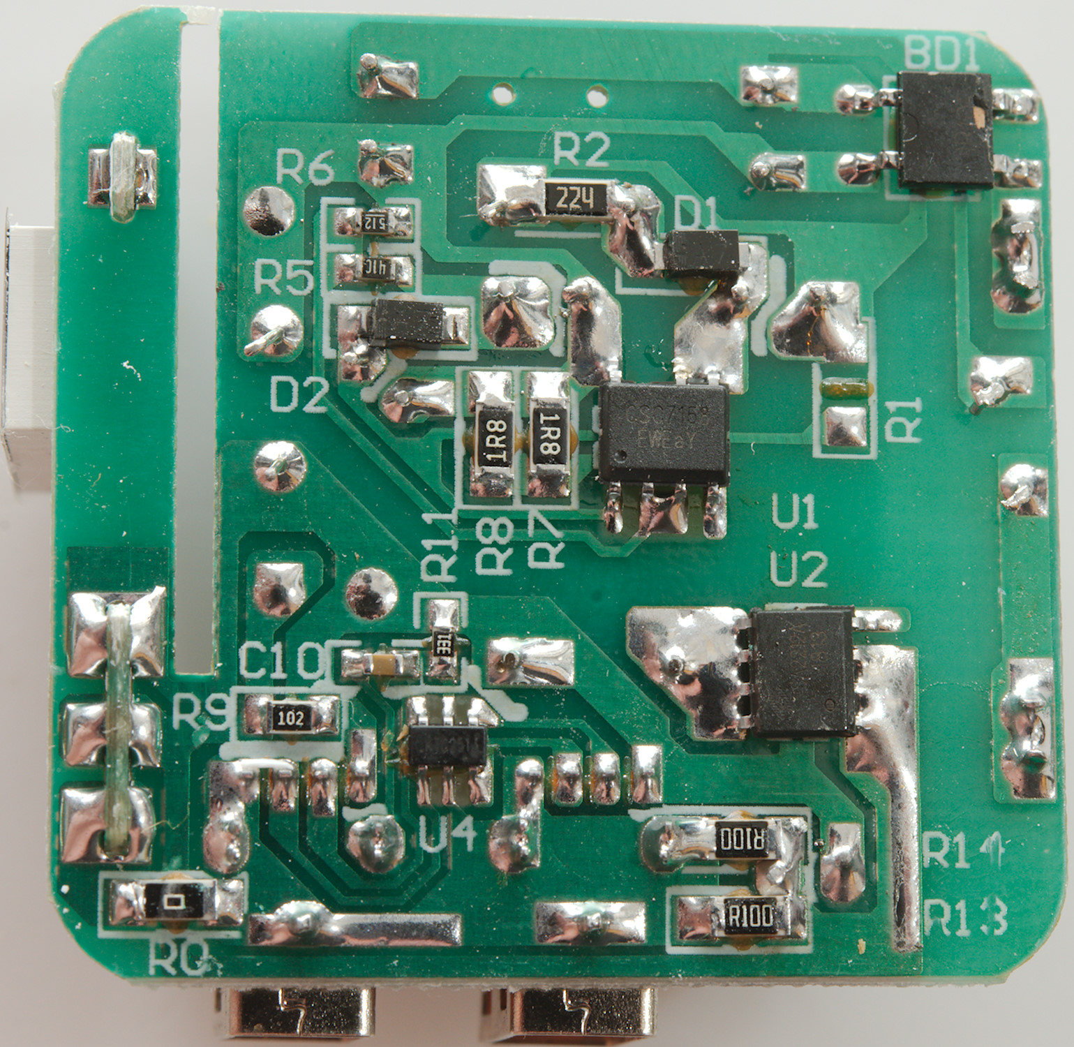
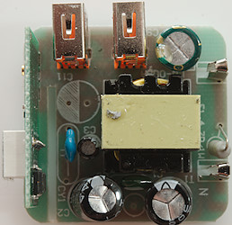
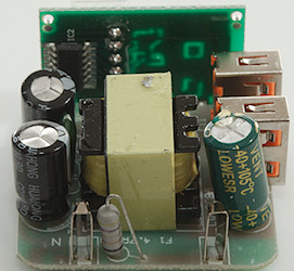
On this side is the input bridge rectifier (BD1), the switcher (U1: CSC7158), on the low volt side is a synchronous rectifier (U2: SA2212A) and a auto coding chip (U4), it is connected to both usb ports, i.e. both are supposed to be auto coding.
There is two R100 resistors in parallel for measuring the current. I have a suspicion that the current sense is at R0, but the sense resistors are R13 & R14 and that is the reason for the difference between the two usb outputs.
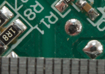
Creepage distance is about 1.5mm, this is way below the required distance.
Testing with 2830 volt and 4242 volt failed the 4242V test, this means it is unsafe in 230V countries.
Conclusion
It is a nice idea with a ammeter on the usb charger, but that is about the only nice thing about this charger. The isolation distance is way too short and it do not use a real safety capacitor, both are very bad for safety, in addition to this the output has a lot of noise.
Stay away from this charger.
Notes
Index of all tested USB power supplies/chargers
Read more about how I test USB power supplies/charger
How does a usb charger work?