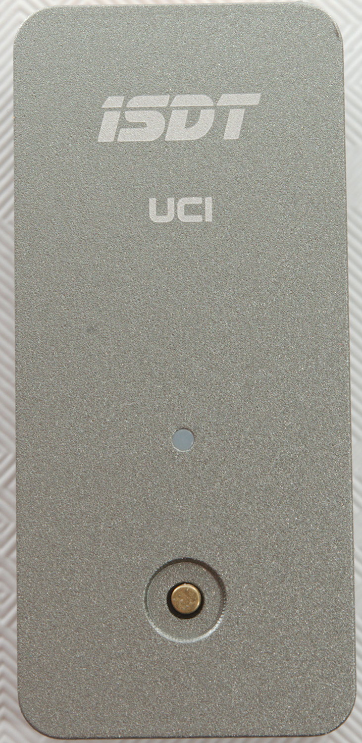
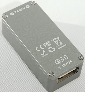
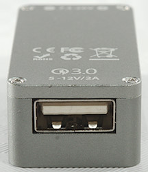
ISDT UC1
Official specifications:
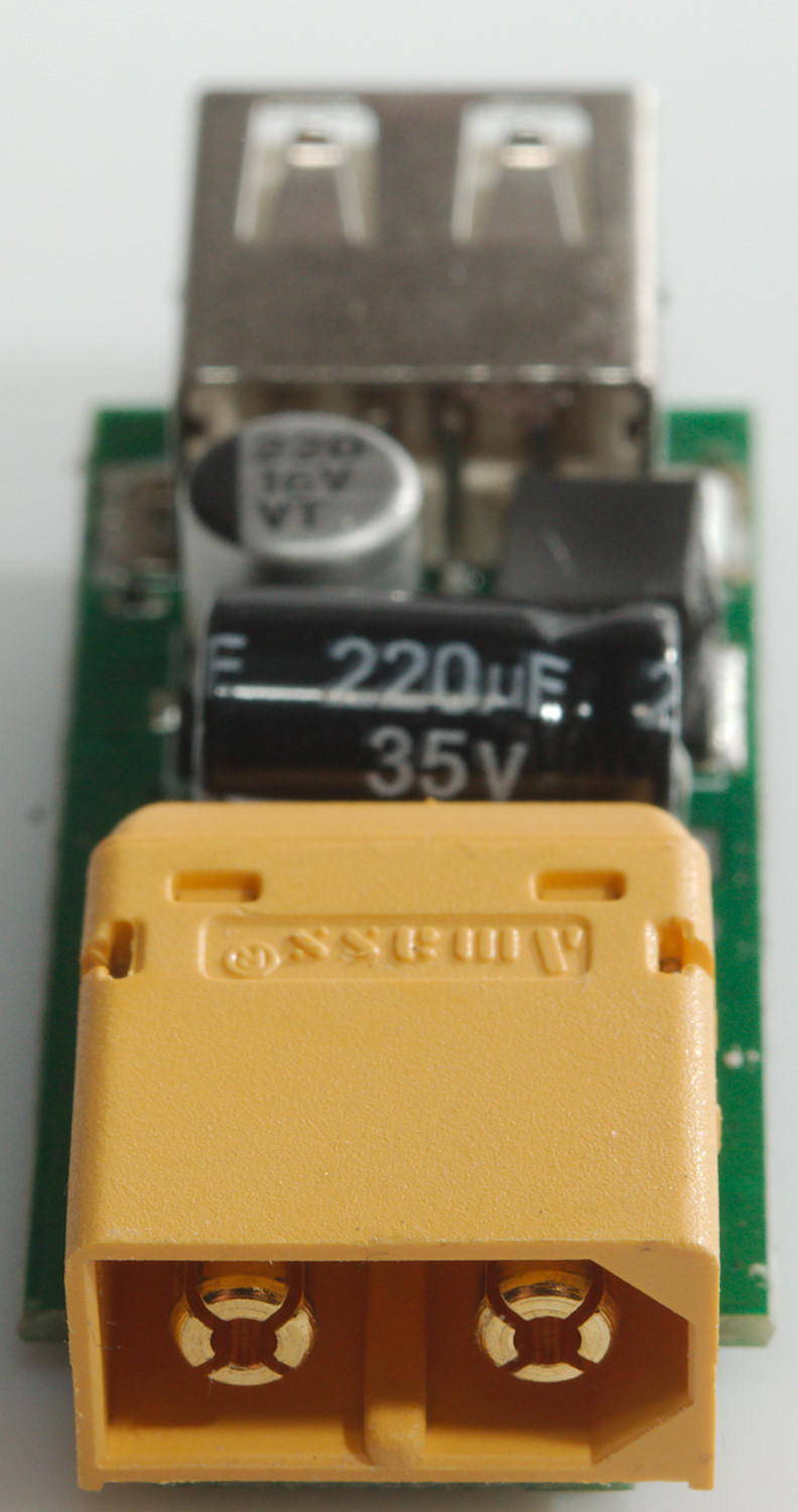
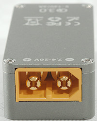
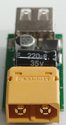
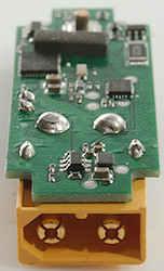
- Input connector: XT60
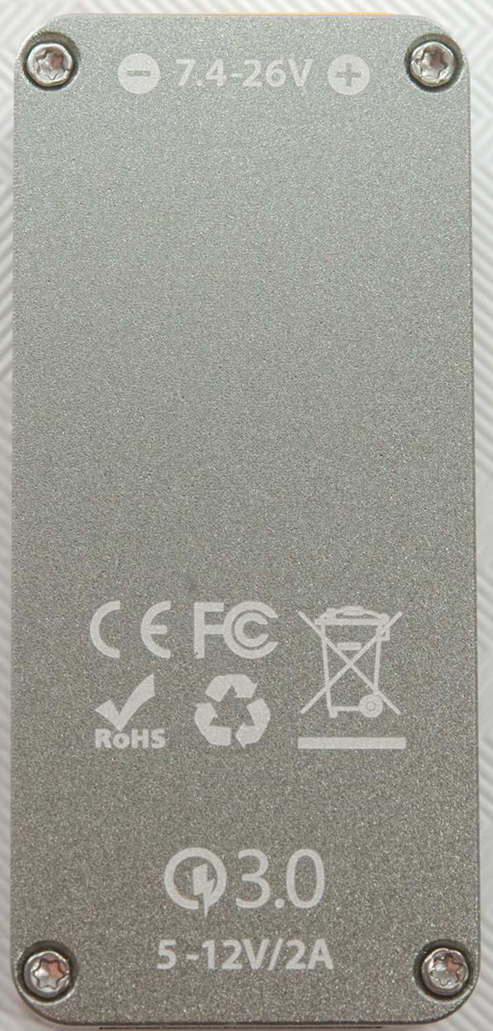
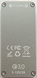
- Input voltage: DC 7.4~26.0V
- Output voltage: 5.0~12.0V
- Maximum output current: 2.0A
- Support protocol: QC 2.0/3.0/FCP/BC 1.2
- Size: 48.5x22x14.4mm
- Weight: 23g
I got it from Banggood
This device will supply USB power from a external LiIon battery pack, it matches connector with many RC applications.


It has a single led a button, these are used to adjust the number of LiIon batteries in series. Hold down the button and the change number of batteries by one or more clicks, hold down again to store. During this process the led will show selected number of batteries.
When used the led will show or under over voltage, but will also disable the output.
Led color:
- Green: Input voltage is in range.
- Flashing cyan: In battery adjust mode.
- Flashing red: Input voltage is too low.
- Flashing magenta: Input voltage is too high, this is only detected when connected, not during use.
Measurements
- USB output support auto coding with Apple 2.4A, Samsung, DCP, QC3, Samsung-AFC, Huawei-FCP
- Minimum QC3 voltage is 3.90V
- Power consumption when idle is 40mA from 24V, will drop to around 5mA when voltage is below 22V
- Power consumption when idle is 40mA from 12V, will drop to around 5mA when voltage is below 11V
- Weight: 23.9g
- Size: 48.5 x 22.0 x 14.3 mm
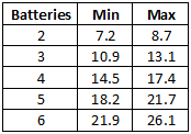
Voltage limits with settings from 2 to 6 batteries. Min/max are the voltages where the device reported error.
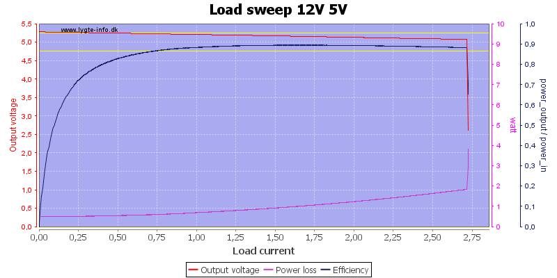
With 12V input and 5V output is can deliver about 2.6A
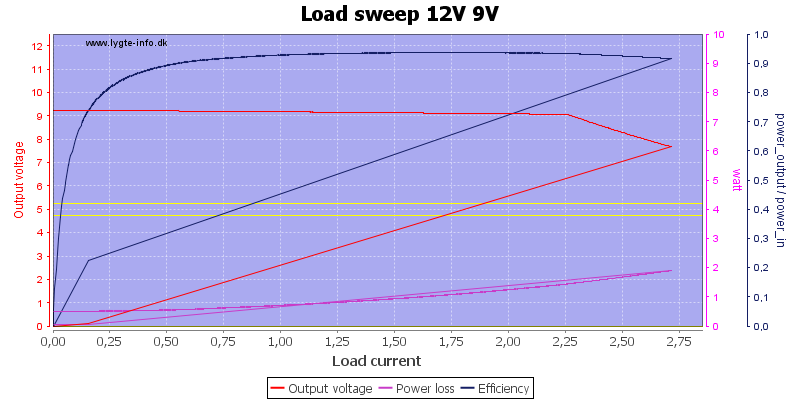
With 12V input and 9V output it is the same 2.6A, but voltage starts to drop at 2.2A, it is still very good for a 9V QC output.
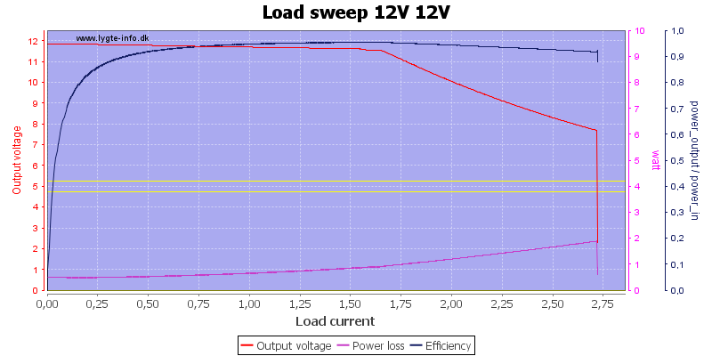
With 12V input the output will be a bit below 12V and it can deliver about 1.7A before starting to drop.
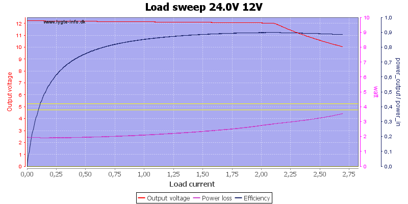
Increasing the input voltage to 24V the output voltage will be 12V and the current increases to about 2.1A
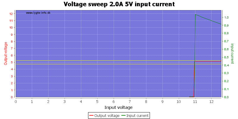
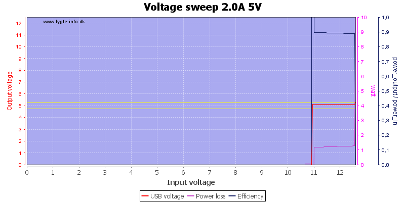
With the device configured for 3 batteries I slowly reduces the input voltage, as can be seen it cuts out at around 11V.
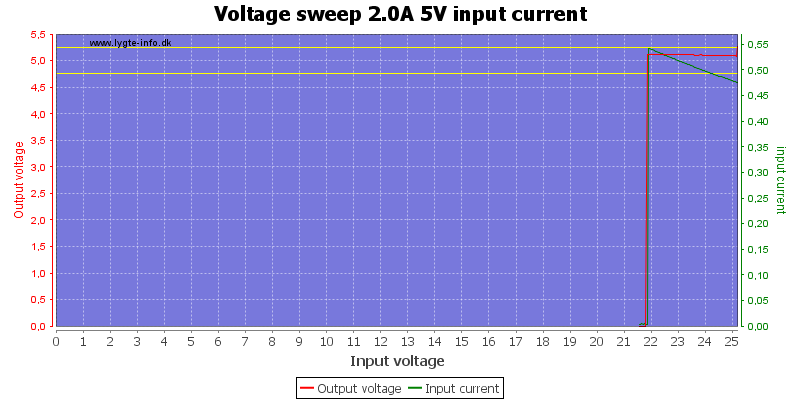
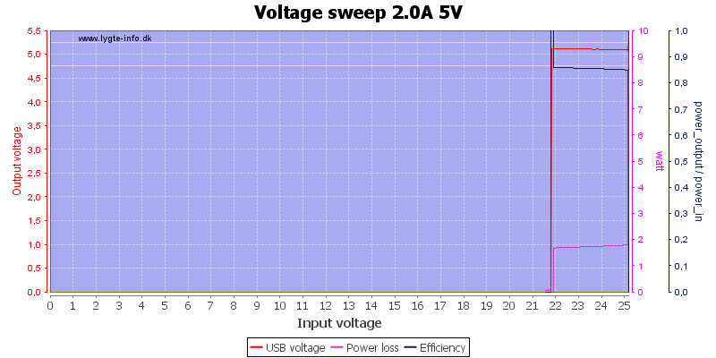
Here I do the same with the device configured for 6 batteries and it will cut out around 22V
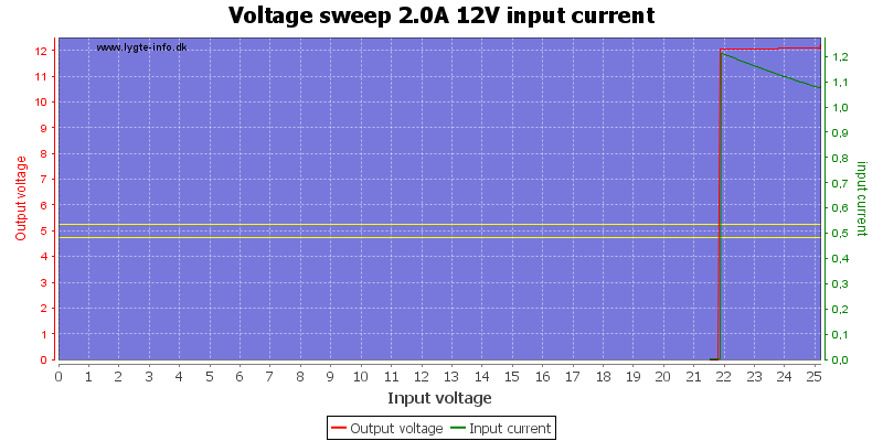
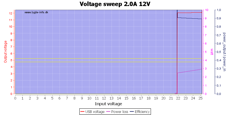
The behaviour is the same when output voltage is at 12V.
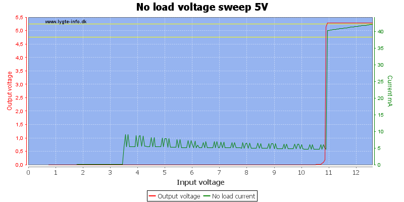
With no load on the output the device will draw about 40mA and drop to around 5mA when battery voltage gets too low. This means it is best to disconnect a empty battery, if it stays connected it will be over discharged after some time.
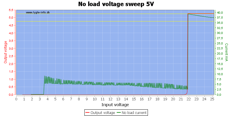
With 24V input the behaviour is similar.
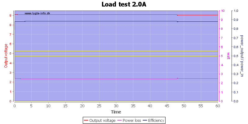
A load test with 24V input and 12V output loaded with 2A could maintain output for at least an hour.
The temperature photos below are taken between 30 minutes and 60 minutes into the one hour test.
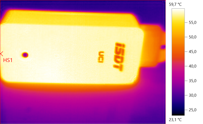
HS1: 59.7°C
It gets around 60°C when working at maximum load with about 2.5W power lost in the device.
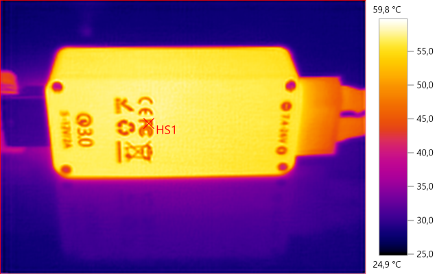
HS1: 59.8°C
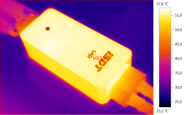
HS1: 57.6°C

With 12V input and 5V 0.5A output the noise is 104mV rms and 414mVpp.
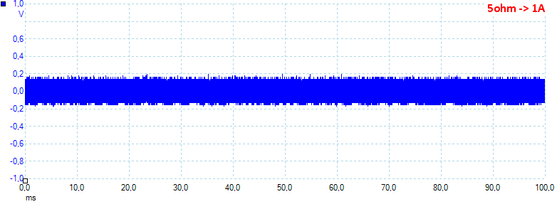
With 12V input and 5V 1.0A output the noise is 110mV rms and 776mVpp.

With 12V input and 5V 2.5A output the noise is 95mV rms and 454mVpp.
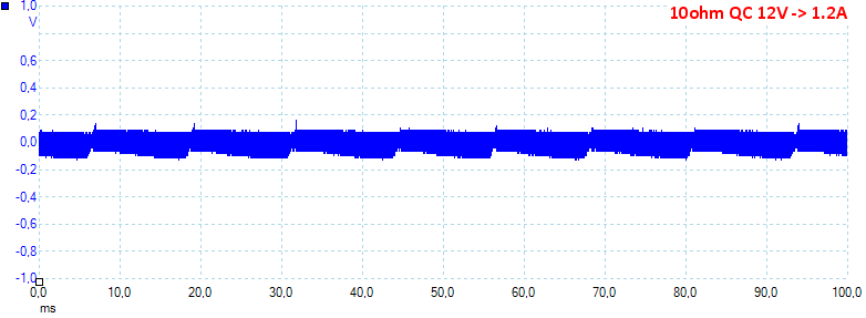
With 12V input and 12V 1.2A output the noise is 67mV rms and 326mVpp.

With 24V input and 5V 2.5A output the noise is 144mV rms and 534mVpp.
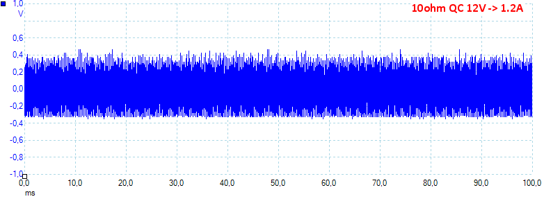
With 24V input and 12V 1.2A output the noise is 186mV rms and 803mVpp. Generally the noise is on the high side.
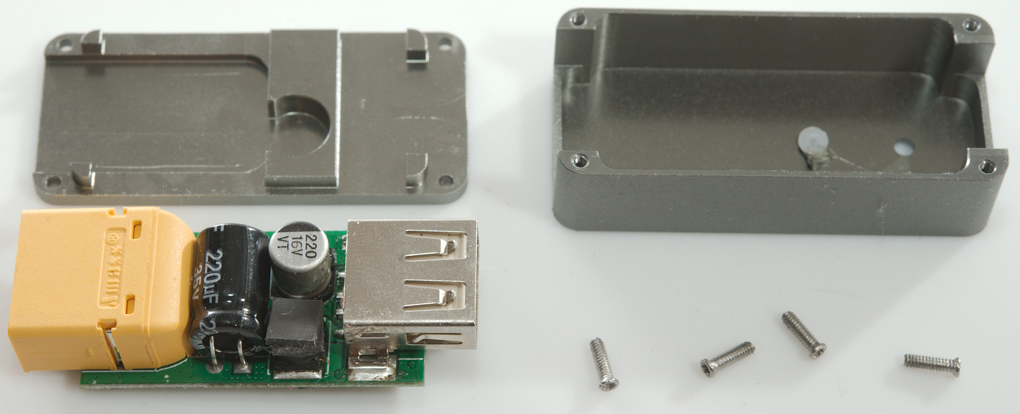
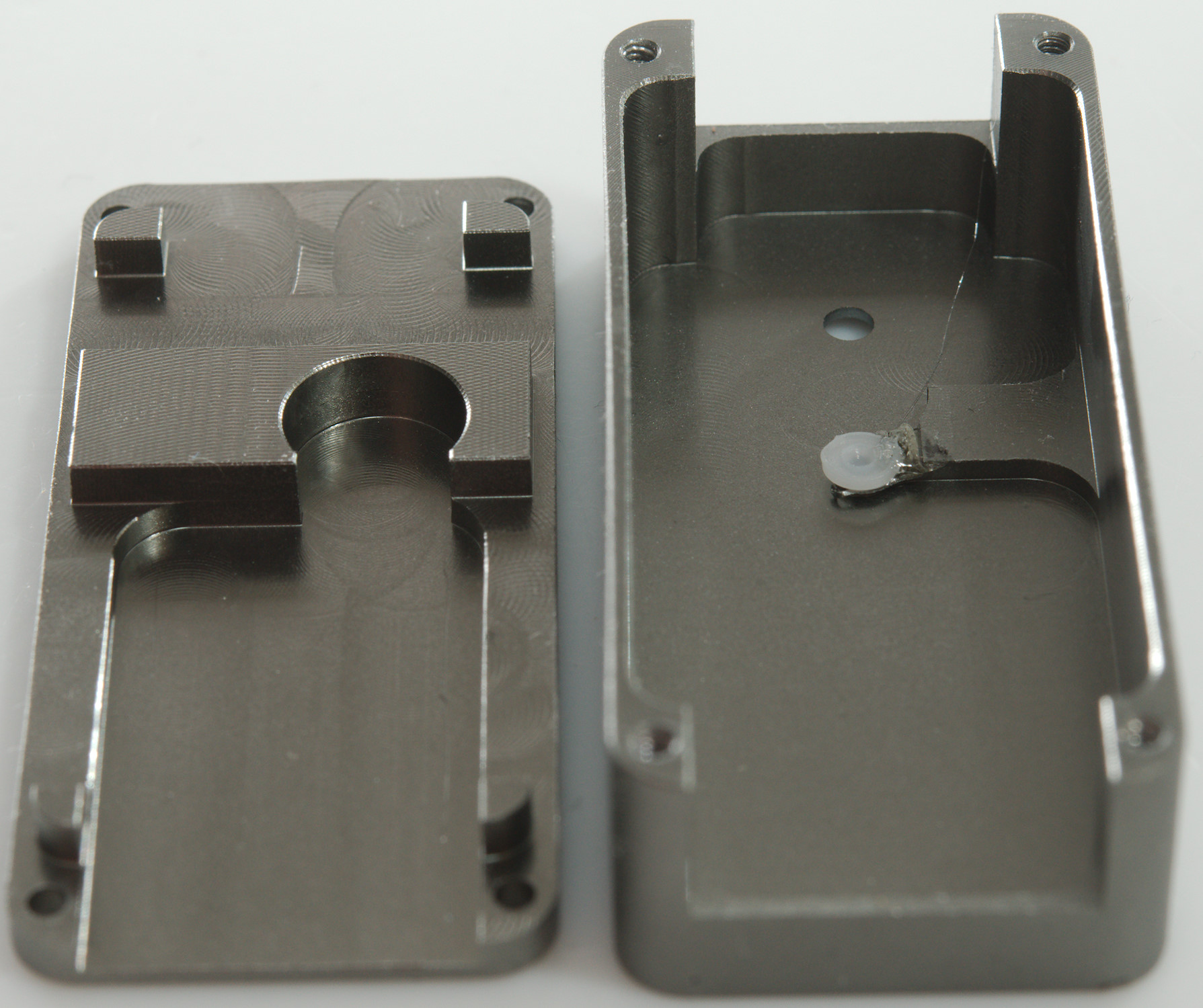
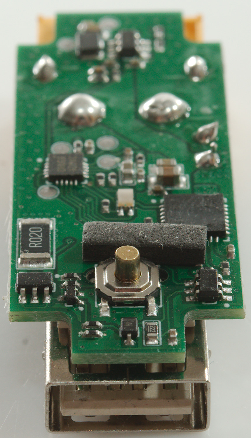
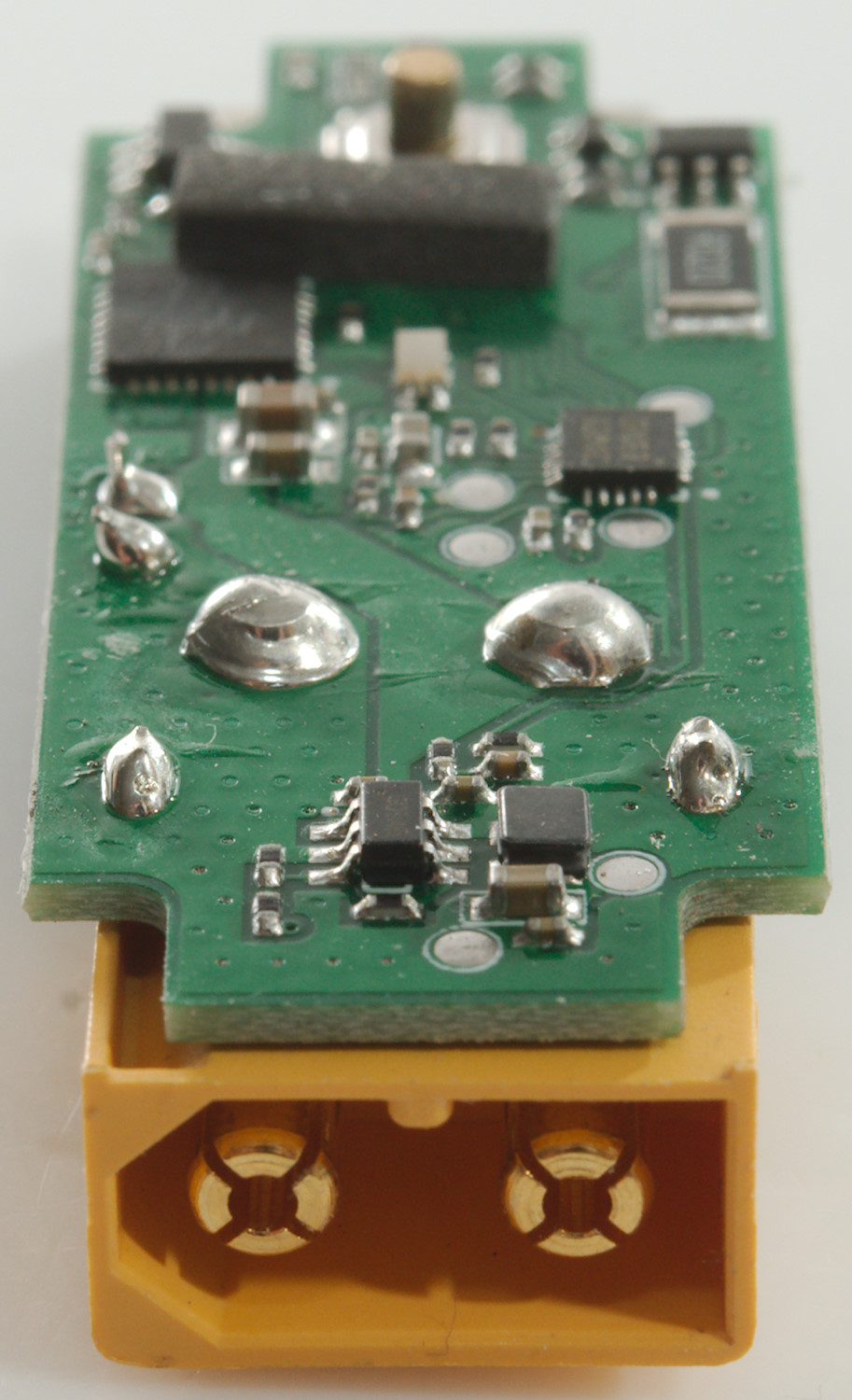
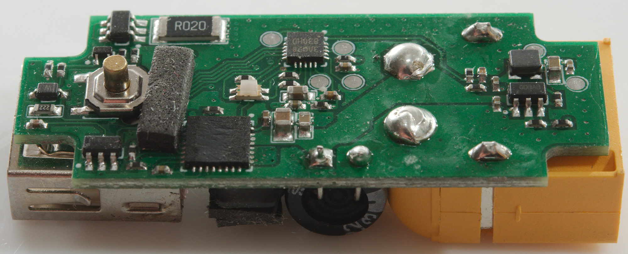
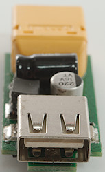
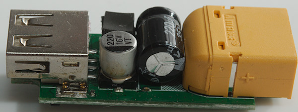
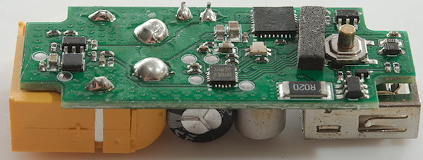
Tear down
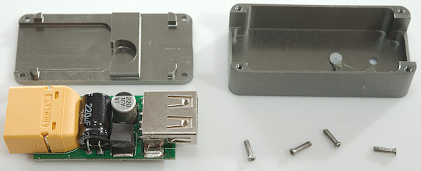
Four small screws (T4) and at it was open.
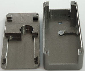
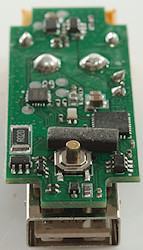
The metal body is shaped to get good contact for cooling.
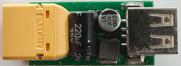
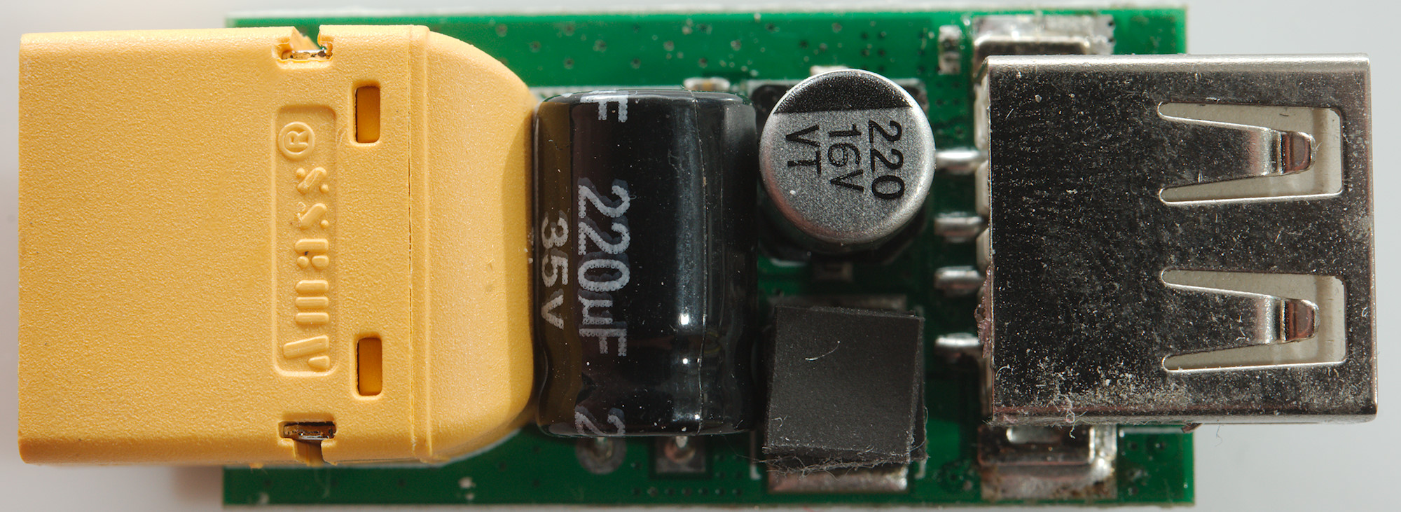
On this side is the connectors, capacitors on both input and output and the inductor for the switcher.
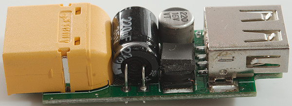
The inductor has a pad on the top to get better cooling contact to the metal enclosure.
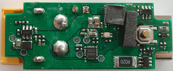
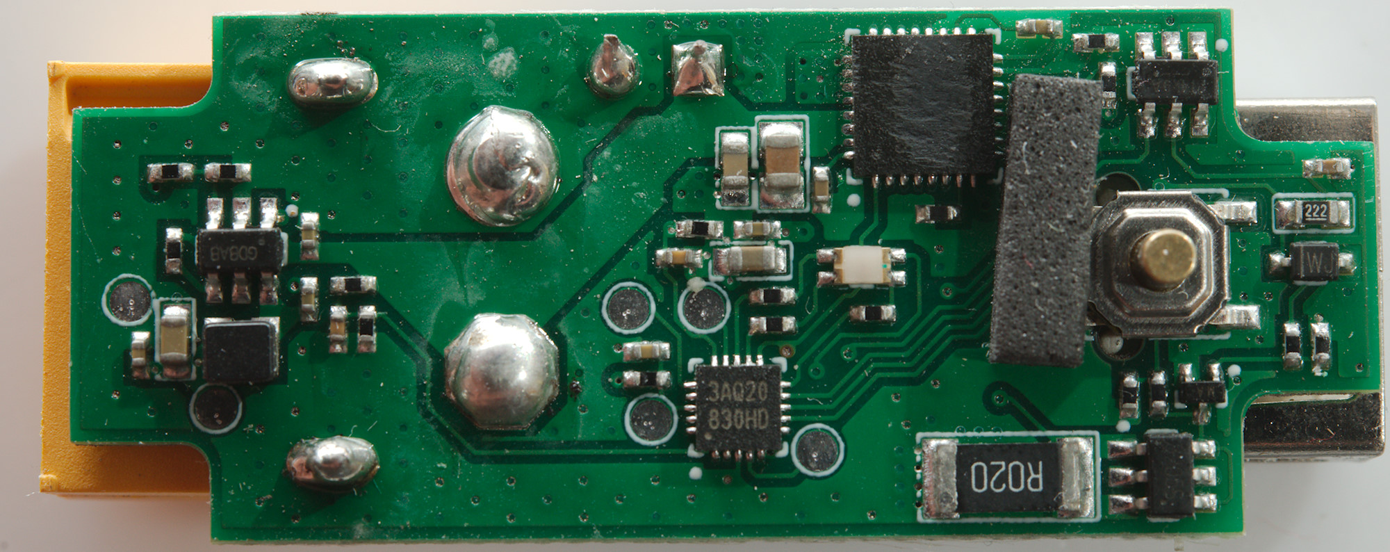
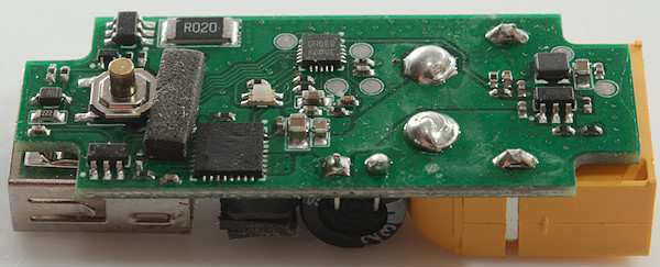
There is a lot of chips on this side, the switcher has a pad on the top for better cooling contact to the enclosure.
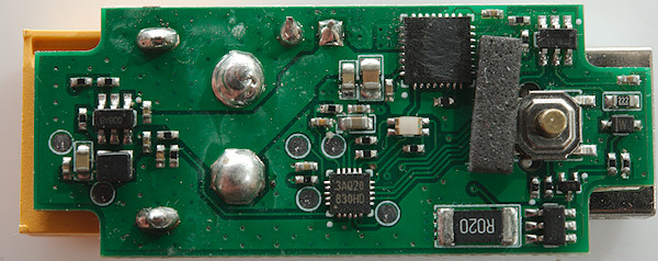
The first chip is voltage regulator (Marked GD8A8 or something similar: 3.3V) to supply the microprocessor (3AQ20: N76E003AQ20 8051 based). There is a switch mode controller with markings removed and next to it a usb controller (FT4: QC2/QC3) and it looks like the switch mode IC cannot easily be switched off, there is a mos transistor (STT8205S dual 6A mos) next to the current sense resistor (R020: 20mOhm). The led is a 4 pin led with 3 color led all connected to the microcontroller with resistors.
Being a low volt device for battery supply there is no need to test with high voltages.
Conclusion
It is an interesting idea to make a USB power supply/bank designed for RC battery packs, but if you use this type of batteries it is a nice little device to carry and it can easily replace a ordinary power bank. The noise is a bit high and may disturb some devices while they are being charged. Being metal it is also very solid.
I will call it fairly good for its special application.
Notes
The USB charger was supplied by Banggood for review.
Read more about how I test USB power supplies/charger
Compare car chargers and other DC supplied chargers