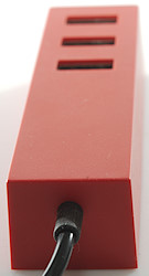
Ikea Lörby USB 5V 3.4A 303.877.07
Official specifications:
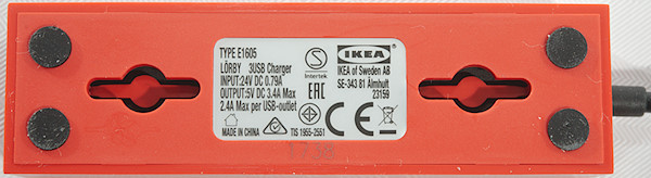
- Type: E1605 LÖRBY
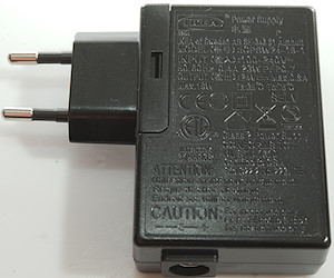
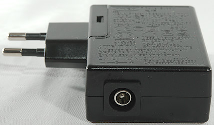
- Input: 24VDC This is obvious only for the red device and do not include the supplied power supply
- Output: 5V DC
- Max load on one output: 2400mA
- Max total load: 3400mA
I got it from Ikea Denmark.
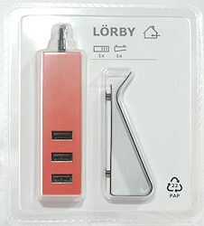
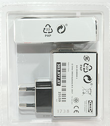
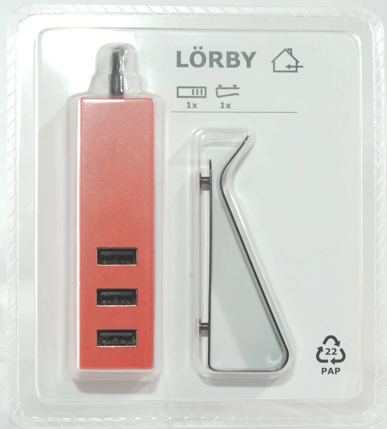
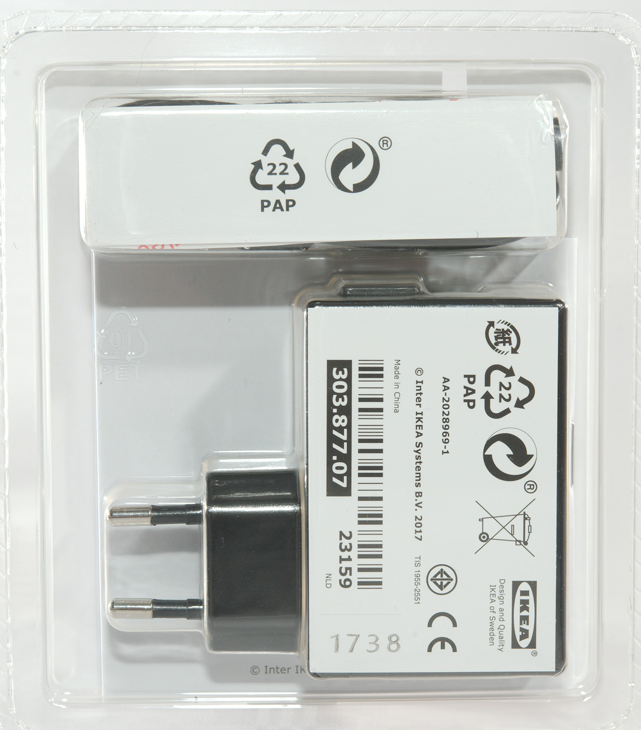
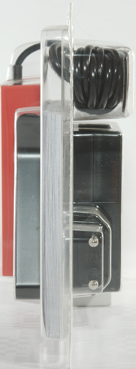
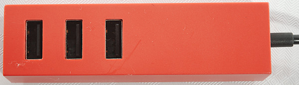
It is packed in plastic where most parts can be seen.
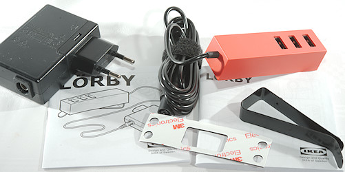
The parts are: Power supply, usb outlet, two manuals, clip, double sided adhesive tape.
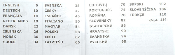
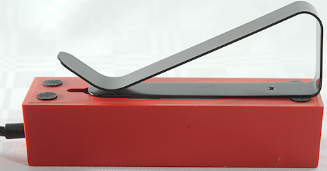
As usual with Ikea the manual is in many languages, it also includes a manual with drawings of possible mountings:
On iron with build in magnets, on table with clip, with screws, with double sided adhesive tape. Each mounting method is carefully illustrated with drawings.
Measurements
- Power consumption when idle is 0.15 watt
- All USB outputs is coded as DCP, Samsung and Apple 2.1A
- Weight: 86.8g for red part with clip and cable, red part without cable and clip is 35-40g
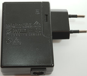
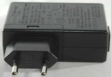
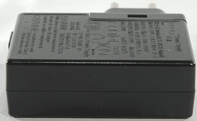
- Weight: 98.2g for power supply
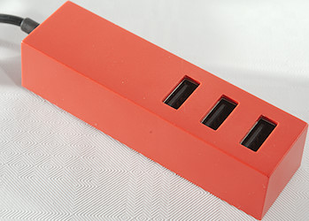
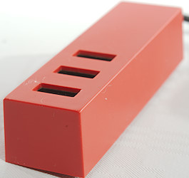
- Size: 88 x 25 x 20.2 mm for red part, ignoring cable
- Size: 87.2 x 73.3 x 24.8 mm for power supply, with cable plugged in the 73.3mm is more like 114mm
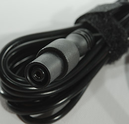
- Cable between USB output and power supply: 178cm

The first output can deliver 2.5A, very precise overload protection for a 2.4A rated output.
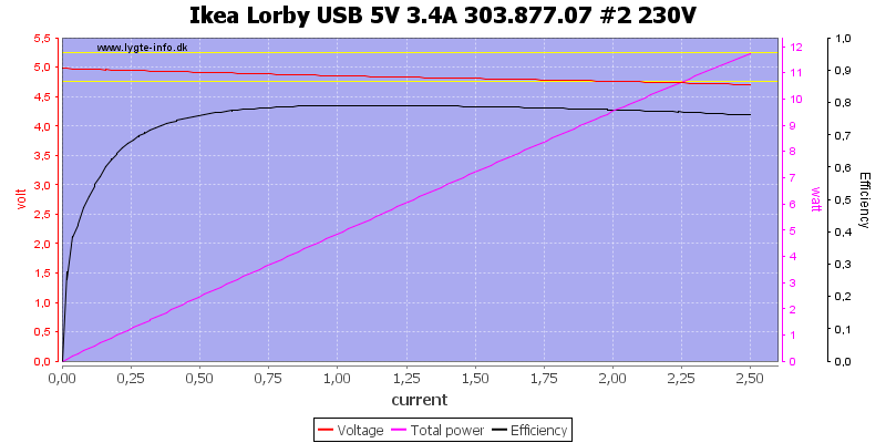
The second output can also deliver 2.5A
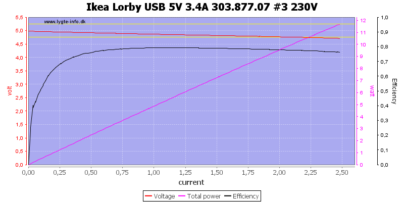
And the third is exactly the same.
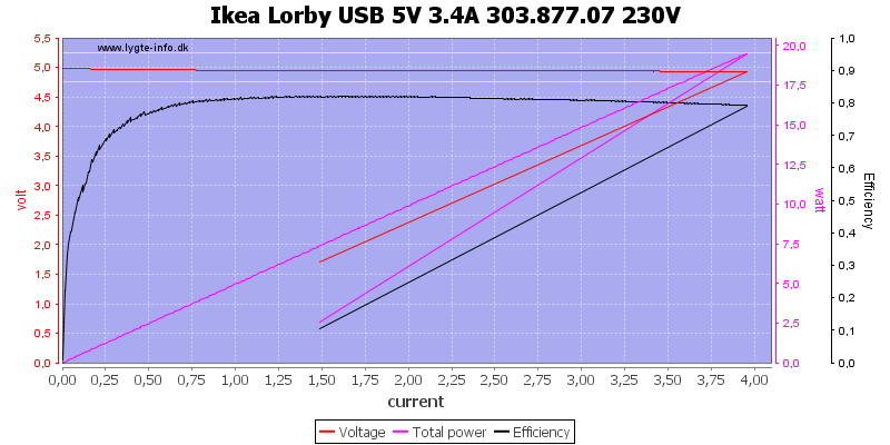
Total output current for all 3 outputs is 4A, rating says 3.5A
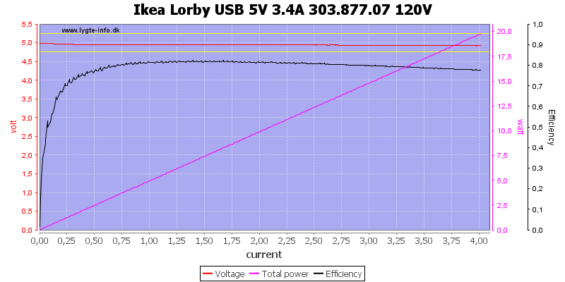
Using 120VAC do not change it.
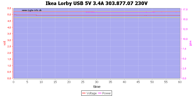
And the charger has no problem delivering rated current for one hour.
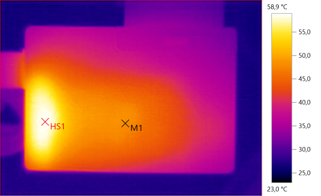
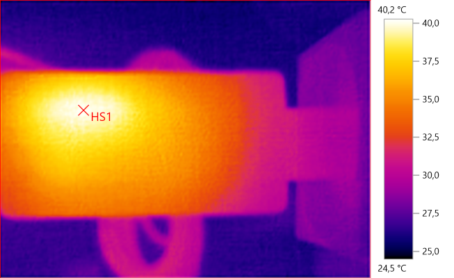
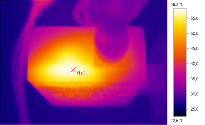
The temperature photos below are taken between 30 minutes and 60 minutes into the one hour test.
M1: 48.1°C, HS1: 58.9°C
The current may be low in the rectifier diode, but it shows up here as HS1.
HS1: 40.2°C
Again the rectifier diode.
HS1: 58.2°C
The square matches the pad on top of the transformer.
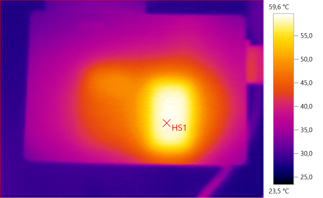
HS1: 59.6°C
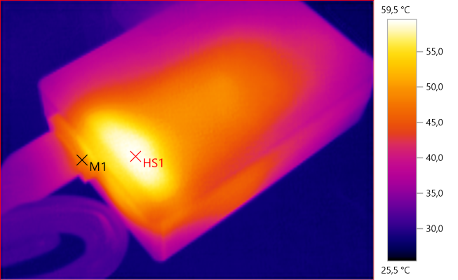
M1: 48.1°C, HS1: 59.5°C
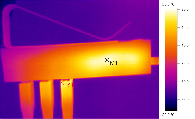
M1: 49.5°C, HS1: 50.3°C
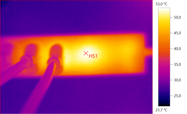
HS1: 53.0°C
HS is the inductor, the two transistors is probably also adding to the heat.
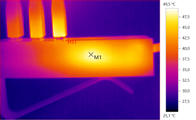
M1: 48.5°C, HS1: 49.5°C
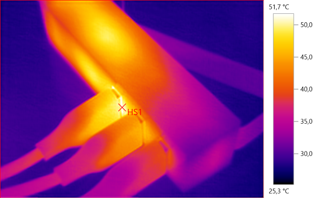
HS1: 51.7°C
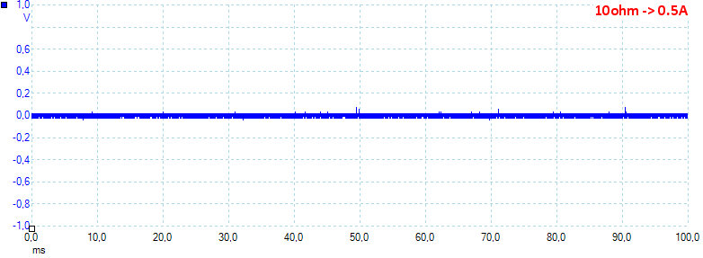
At 0.5A the noise is 16mV rms and 174mVpp.
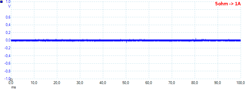
At 1A the noise is 17mV rms and 164mVpp.
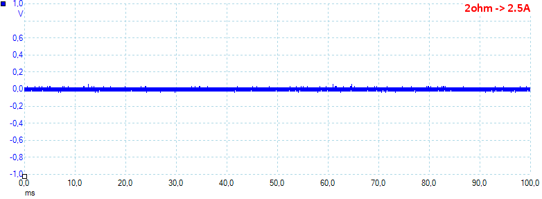
At 2.5A the noise is 16mV rms and 174mVpp.
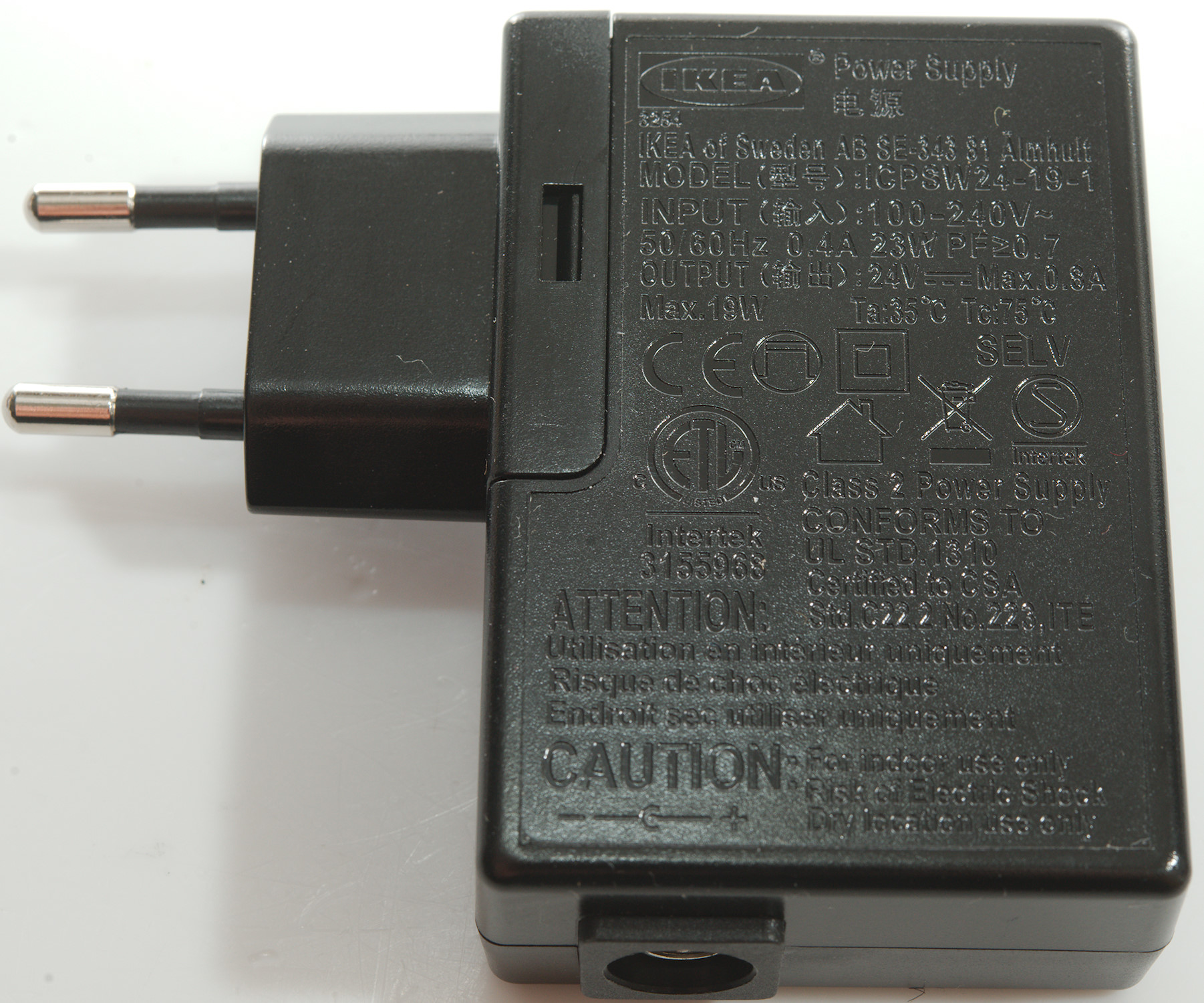
Tear down power supply
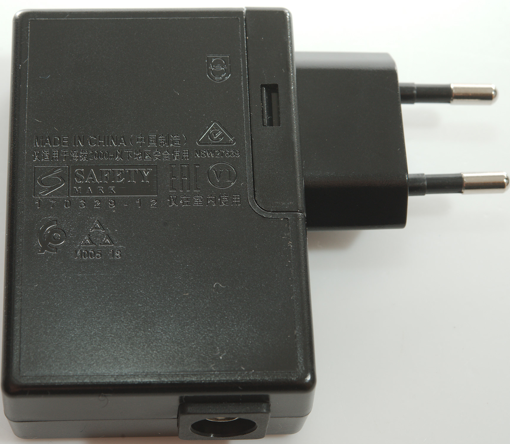
This is not a USB power supply with 5V, but a 24V supply, this means much less current in the rectifier diode, rating says output current is 0.8A.
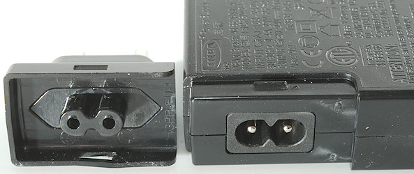
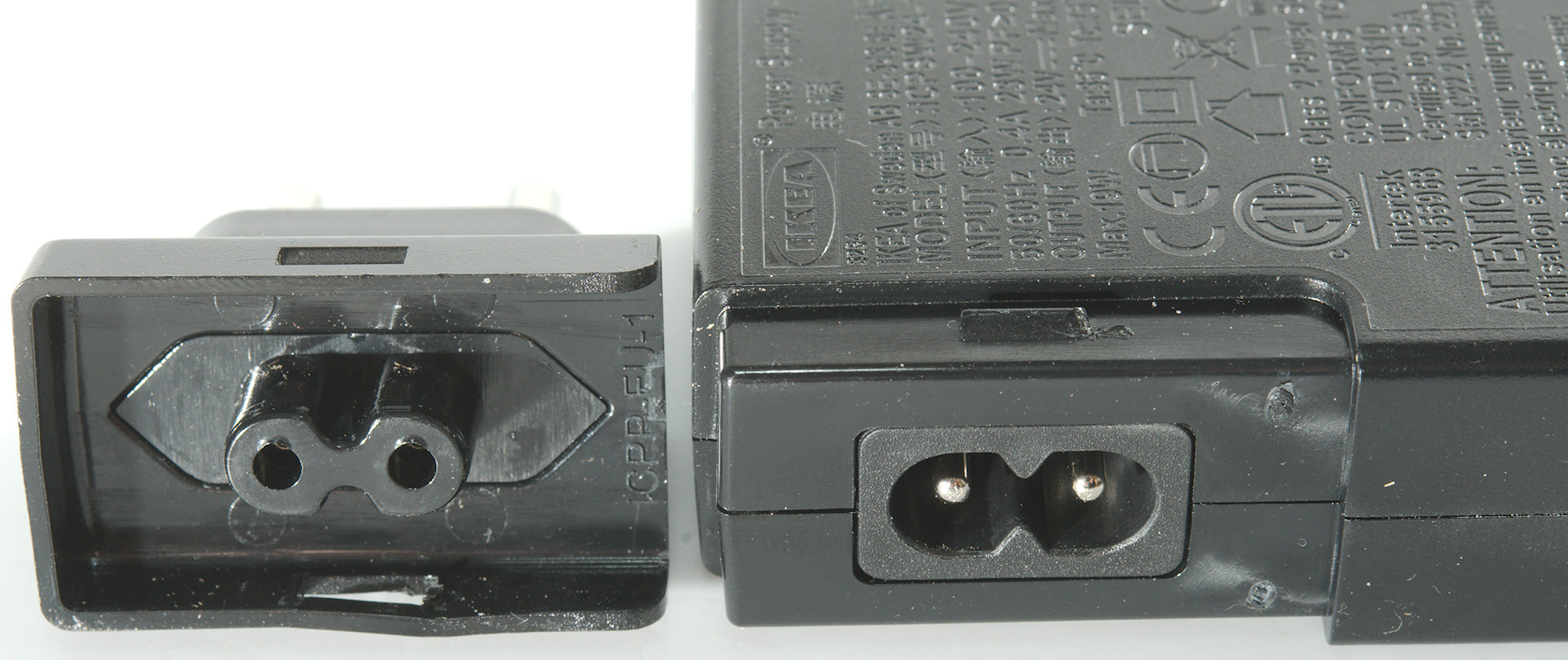
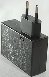
The mains plug can be removed, but it is not designed for it.
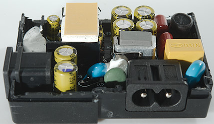
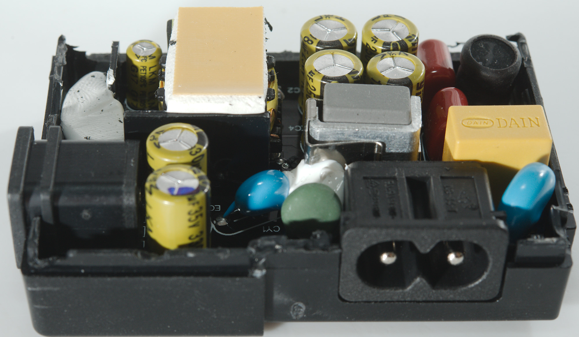
A bit of cutting and I could open the charger, the circuit board fits very nicely into the enclosure.
And was easy enough to remove when the enclosure was open.
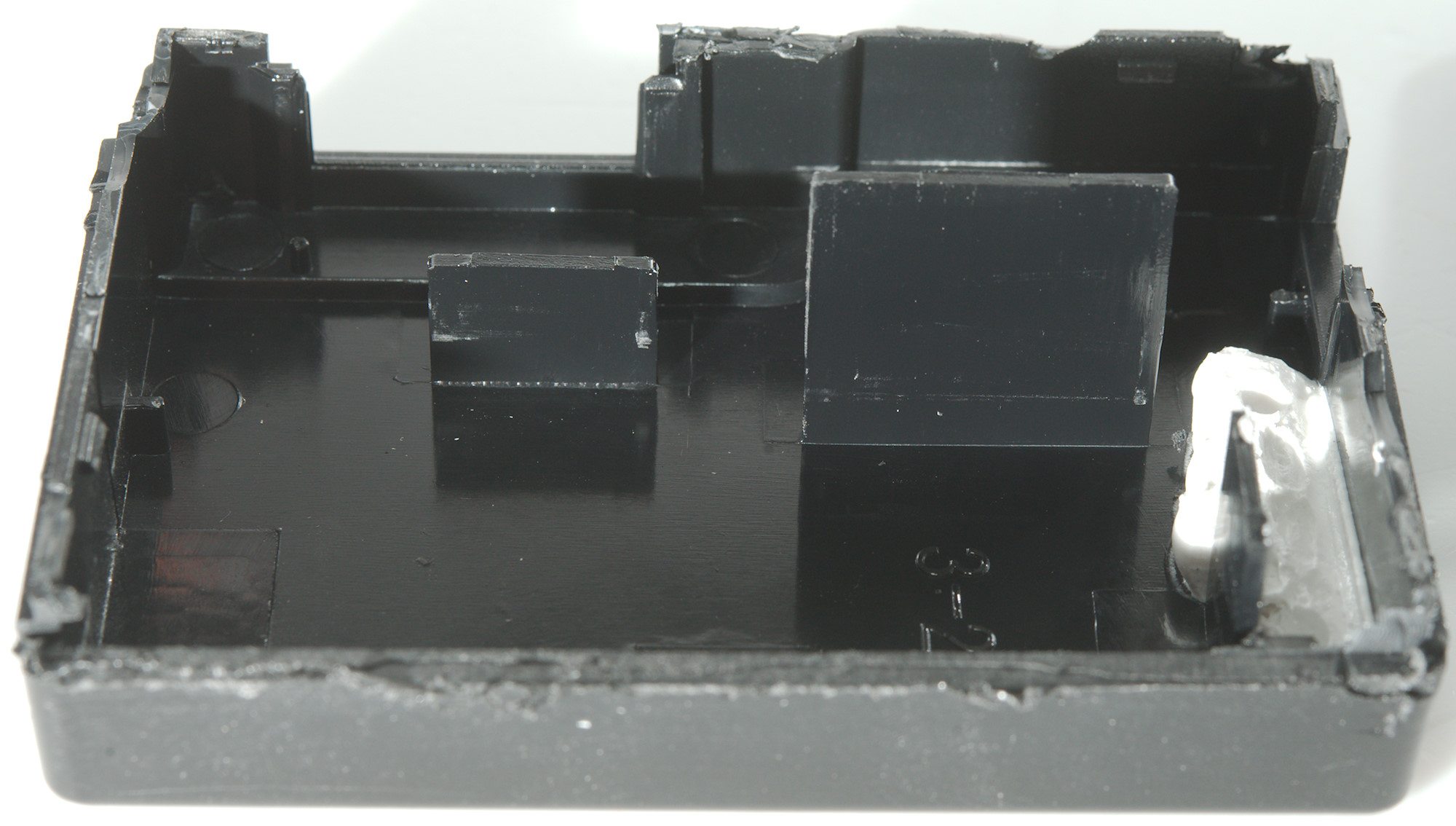
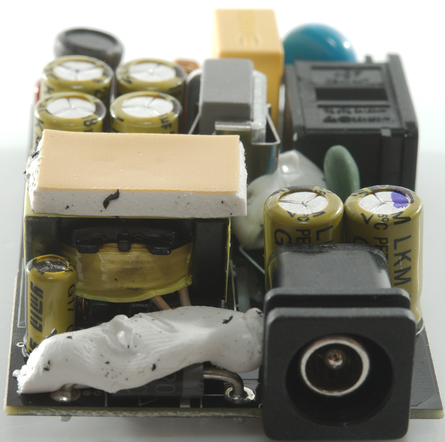
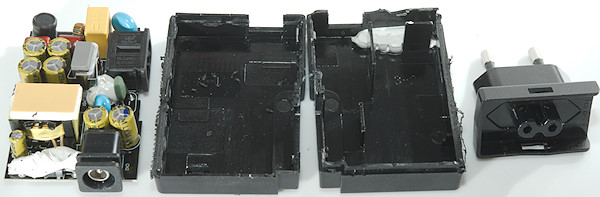
The 3 plastic shields goes through slots in the circuit board and improves isolation. Two of them can be seen above where the circuit board is in the enclosure.
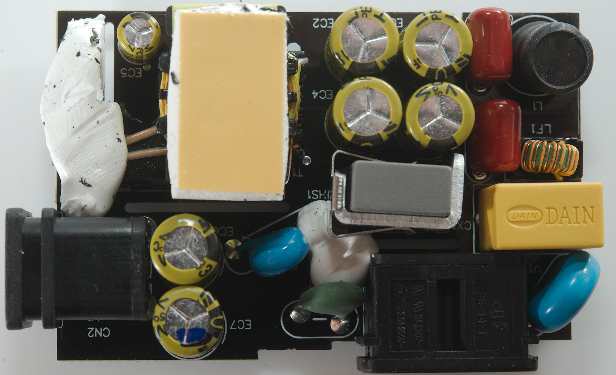
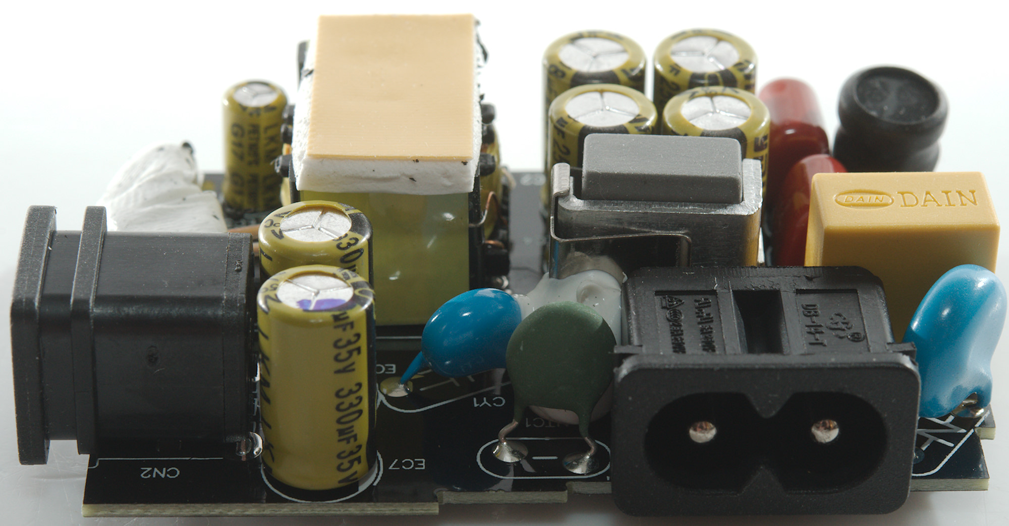
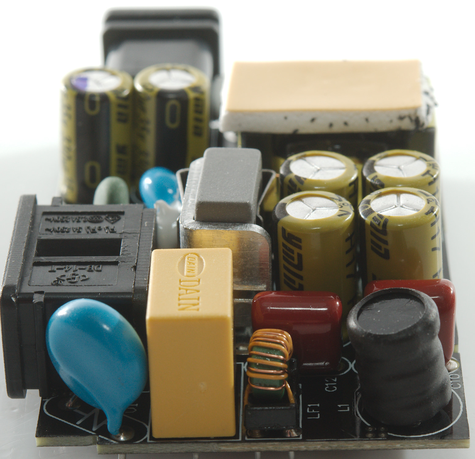
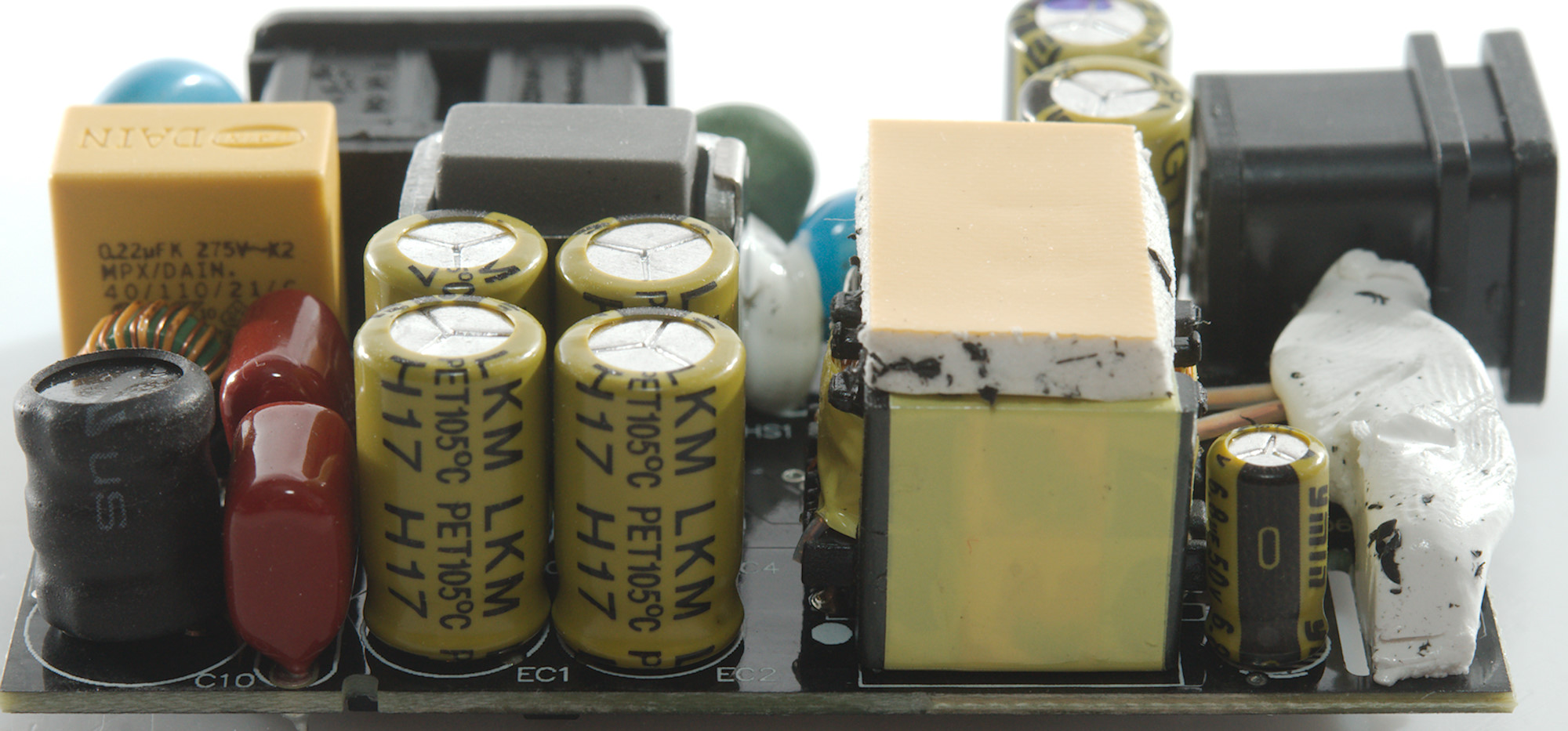
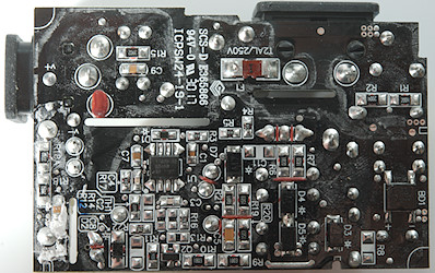
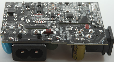
At the mains input is a inrush current limiter (NTC1) and transient protection (V1: 470V MOV), there is a common mode coil (LF1) and a inductor (L1) before the capacitor bank (EC1, EC2, EC3, EC4: 18uF 250V), that is two series and two parallel for a final result of 18uF 500V. The mains switcher transistor is isolated and mounted on a heatsink.
Between the mains side and the low volt side is a safety capacitor (CY1). The low volt side has a regular rectifier diode below the white stuff and two capacitors in parallel (EC6 & EC7: 330uF 35V).
The isolating booth and clip for the switching transistor and a look at it without these.


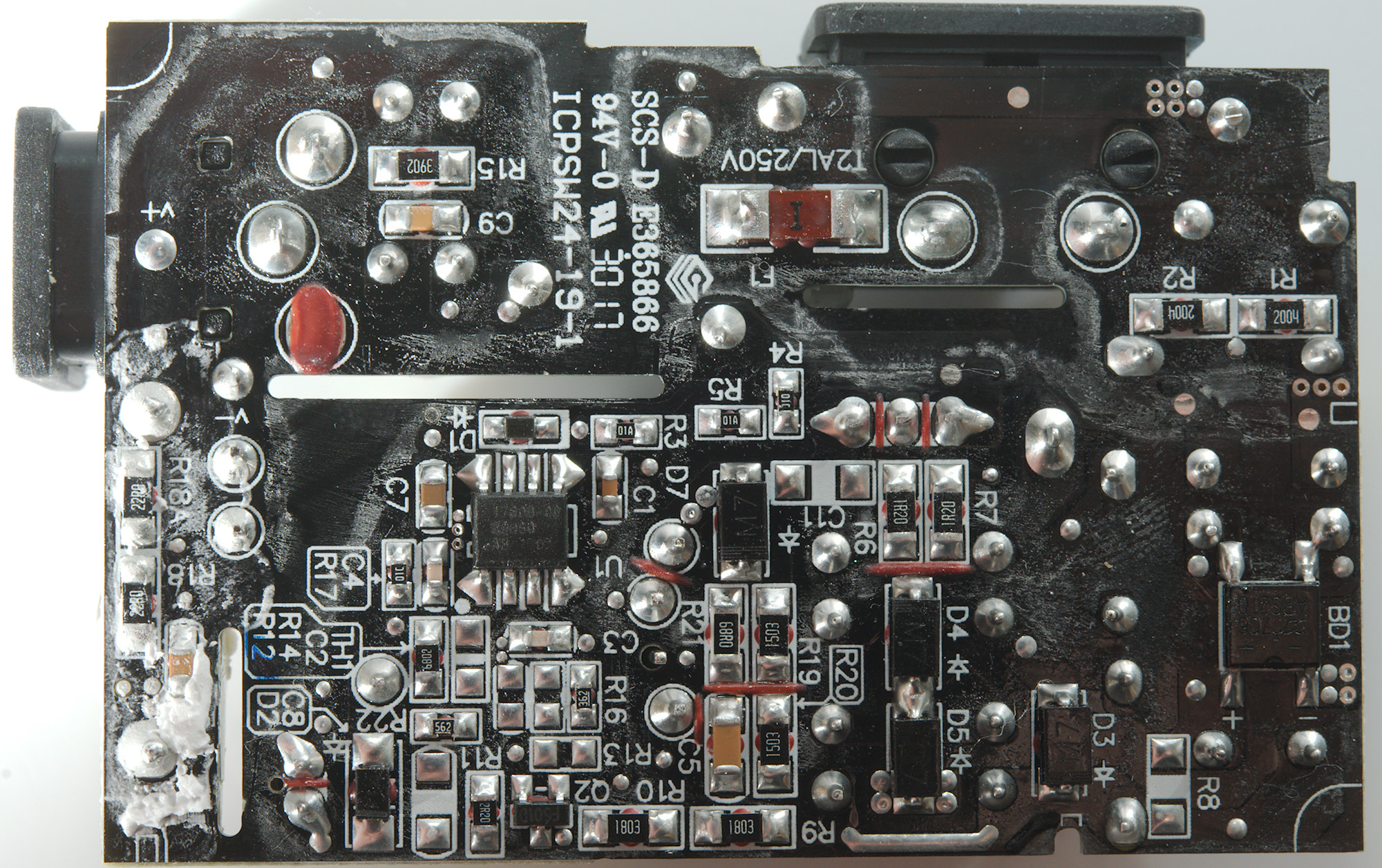
THe mains fuse (F1) is on this side, together with the bridge rectifier (BD1). There is also a mains switcher controller (U1: Marked: 1760B-00 / R9HSQ / AB 1707).
The distance between mains and low volt side is large enough.
Testing with 2830 volt and 4242 volt between mains and low volt side, did not show any safety problems.
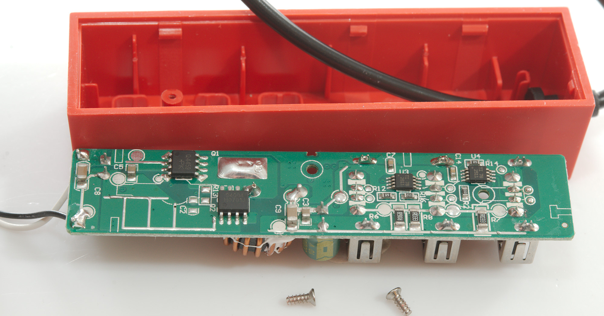
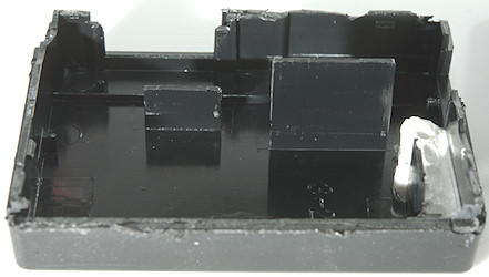
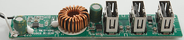
Tear down USB outlet
This outlet must converter the 24V from the power supply to 5V for the USB connectors.

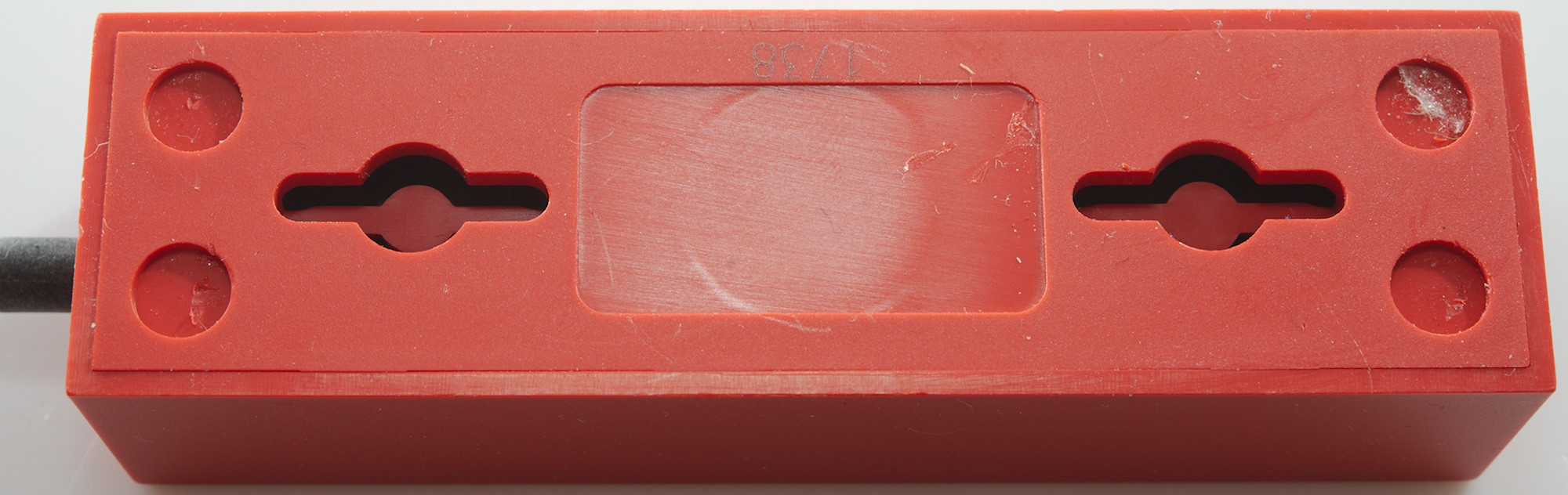
No screws in this enclosure
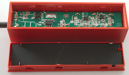
It used clips.

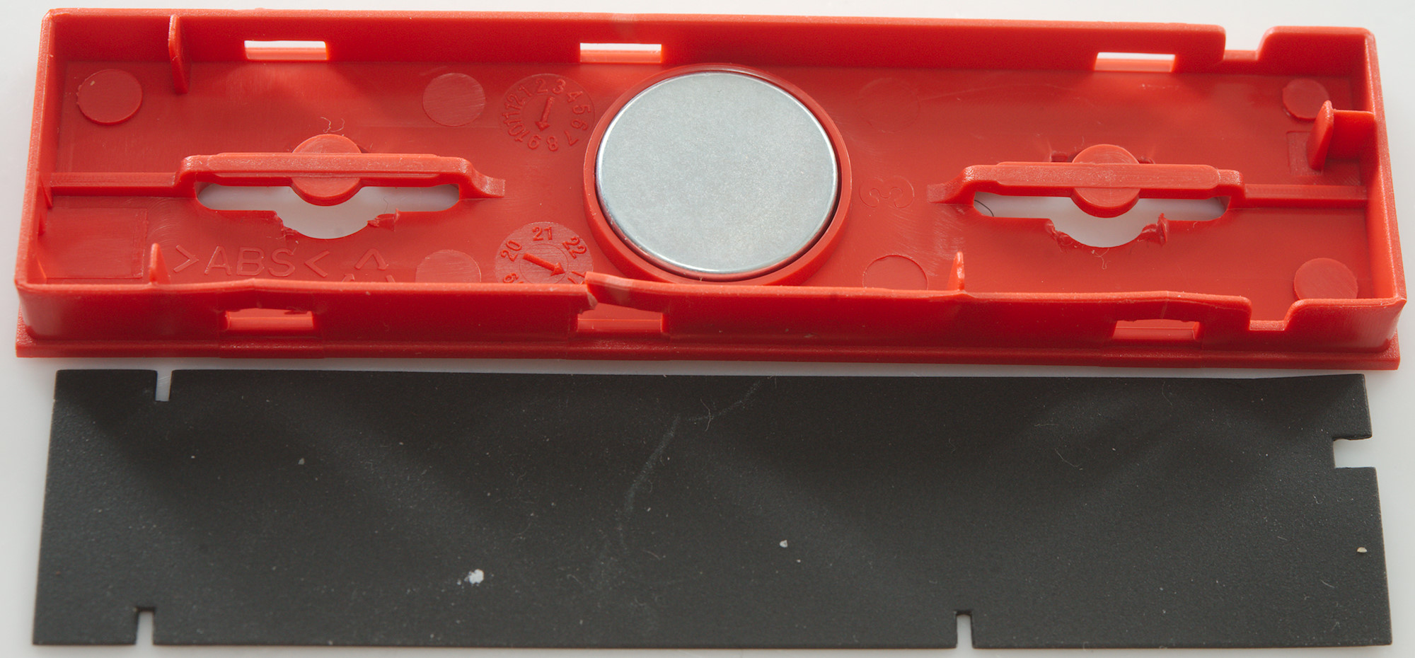
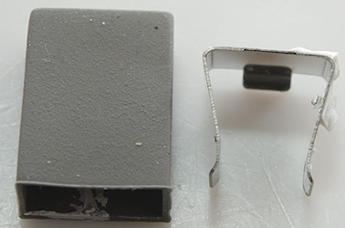
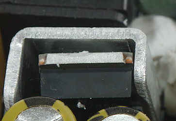
The magnet and the isolating and protection paper.
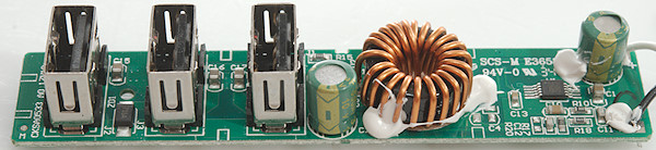
The is a lot of electronic in this outlet.
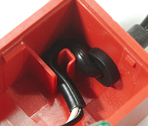
The cable has some strain relief.

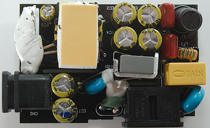
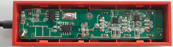
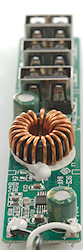
A had to remove two small screws to get the circuit board out.
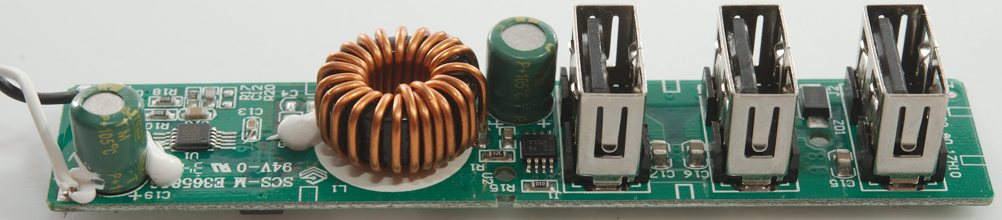
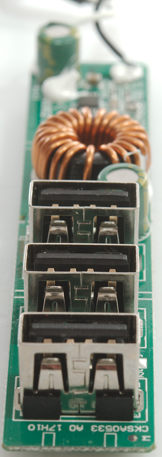
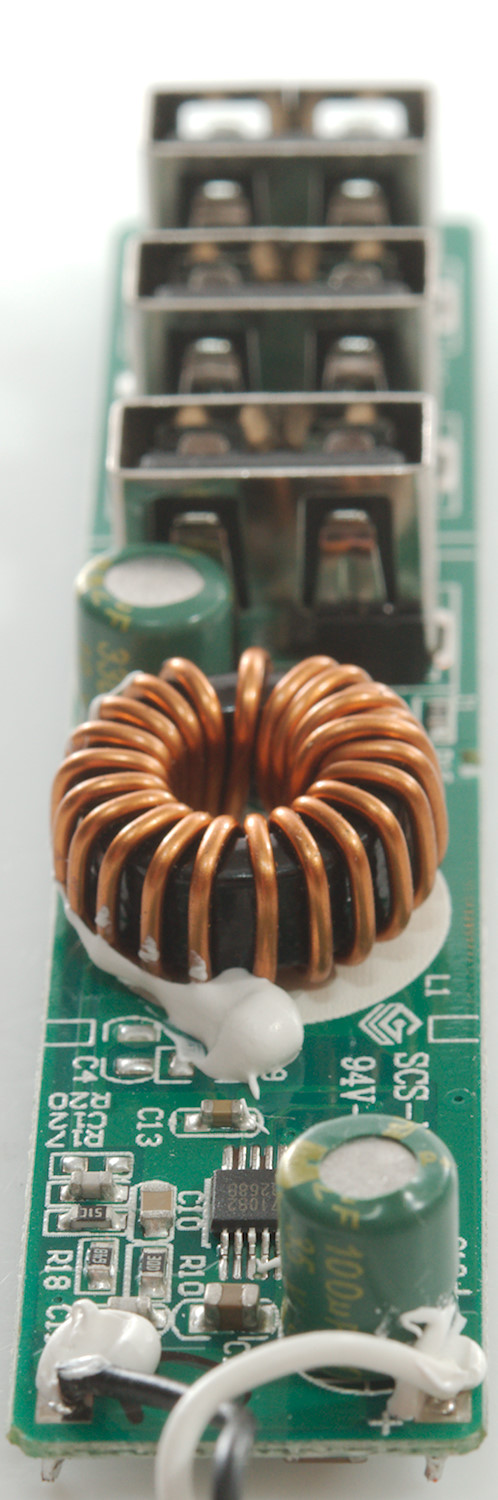
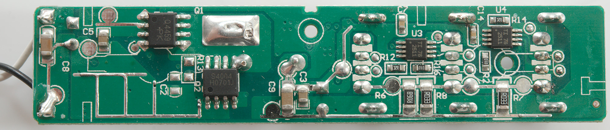
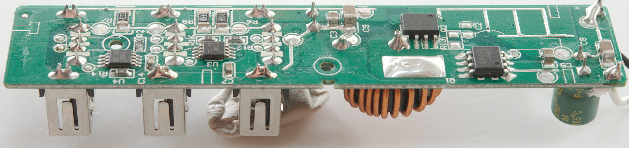
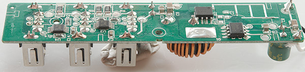
On this side of the circuit board are input capacitors, a switcher controller (U1: Marked 710B2 / 3268B) and the inductor (L1). There is also a smart USB charge controller (U2: TPS2511).
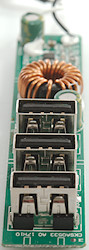
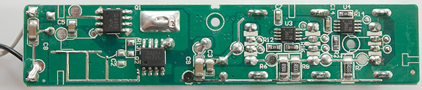
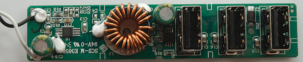
On this side is two power transistors (Q1: MCQ4459 & Q2: Marked S4004 / H0701J) and two more smart USB charge controllers (U3 & U4: TPS2511).
Conclusion
As a USB charger it is a bit low on power for 3 USB outputs, charging two devices at a time is more realistic. The noise is low and the safety is good and with auto coding most devices can get a fairly fast charge from it.
A nice detail with this Ikea charger is that they have look at how to deploy it in the home with all the different mounting options, the actual USB outlet is also very compact.
Notes
Index of all tested USB power supplies/chargers
Read more about how I test USB power supplies/charger
How does a usb charger work?