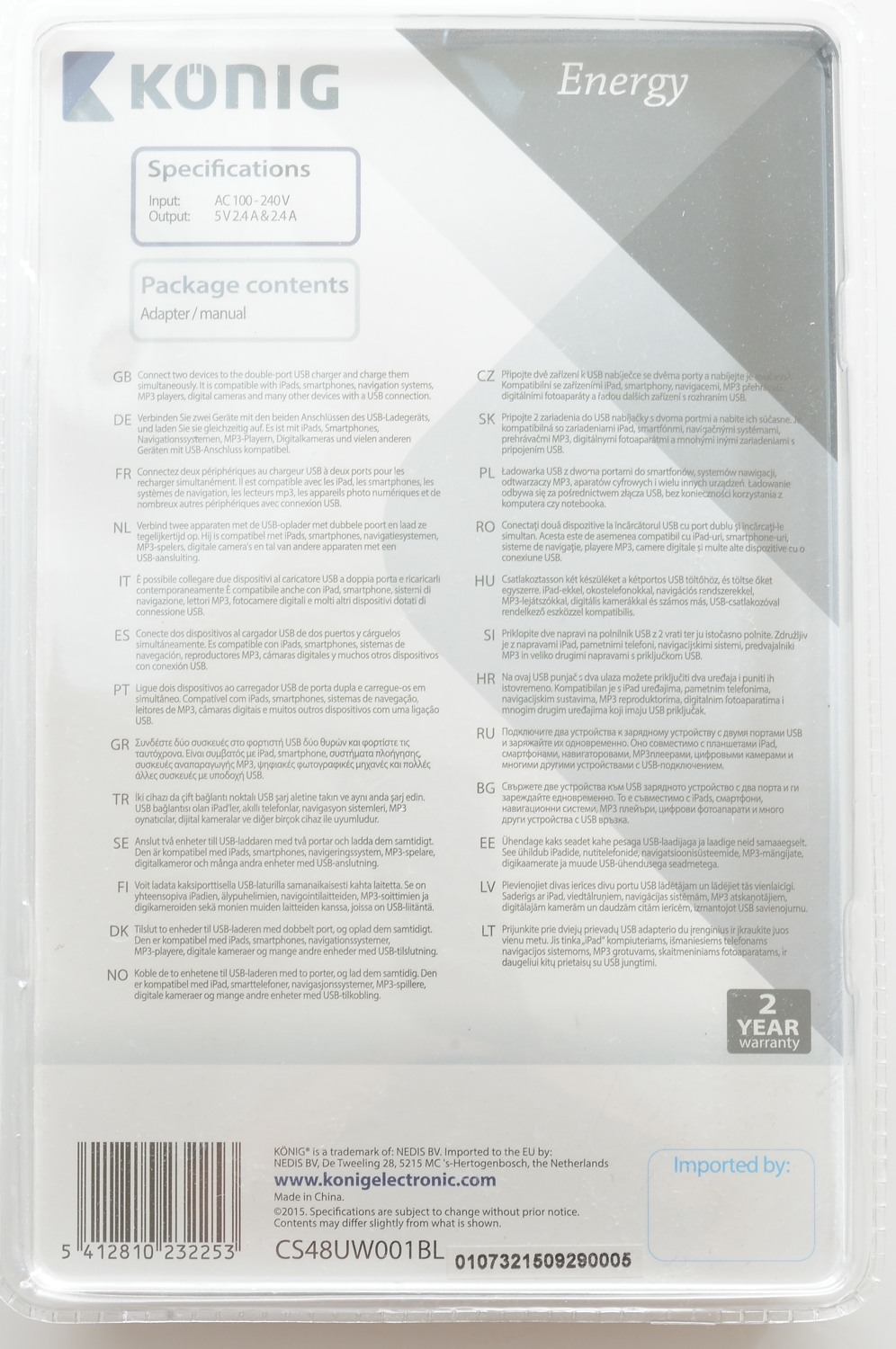
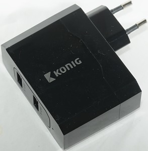
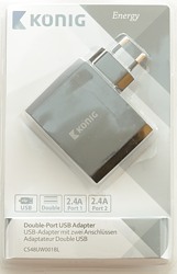
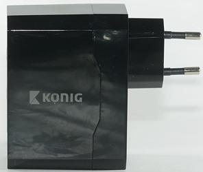
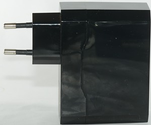
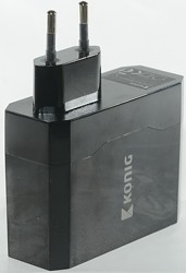
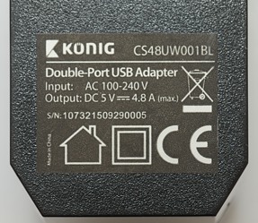
Konig 2x2.4A CS48UW001BL
Official specifications:
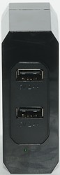
- No. of outputs: 2
- Usage: Home
- Socket type: USB
- Output voltage: 5 VDC
- Cable type: No Cable Included
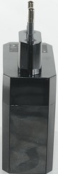
- Power plug: Euro / Type C (CEE 7/16)
- Colour: Black
- Voltage: AC 100 - 240 V
- Output current: 4.8 A
- Max output current per port: 2x 2.4A
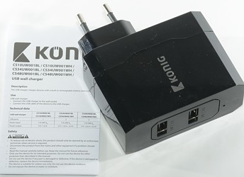
The box contains the charger and a multi language and multi device instruction/data sheet without any useful information.
There is a small hole below the usb connectors, behind the hole is a green led (See tear down).
Measurements
- Power consumption when idle is 0.1 watt
- Both usb outputs has automatic coding with Apple 2.4A as max.
- The two output ports are in parallel.
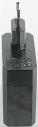
- Weight: 111g
- Size: 95 x 78 x 30.5mm
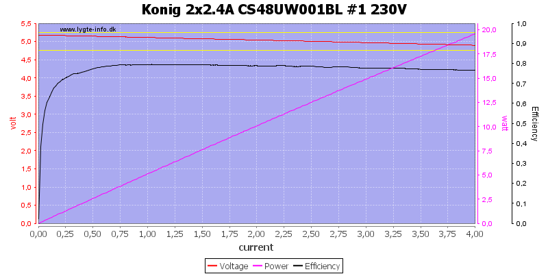
The charger has fairly good efficiency and no individual port overload protections.
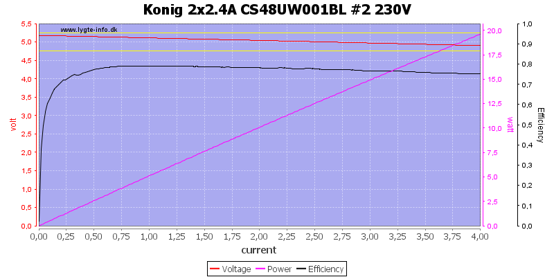
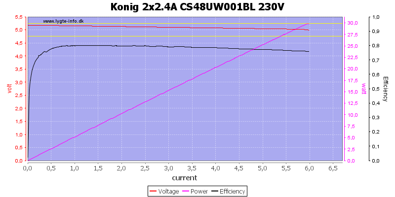
It has a total over limit at about 6A.
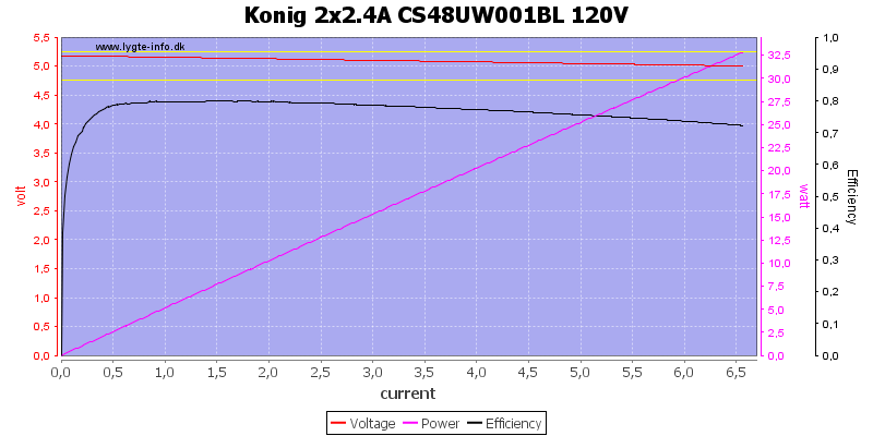
At 120VAC the overload limit is increasse to 6.5A
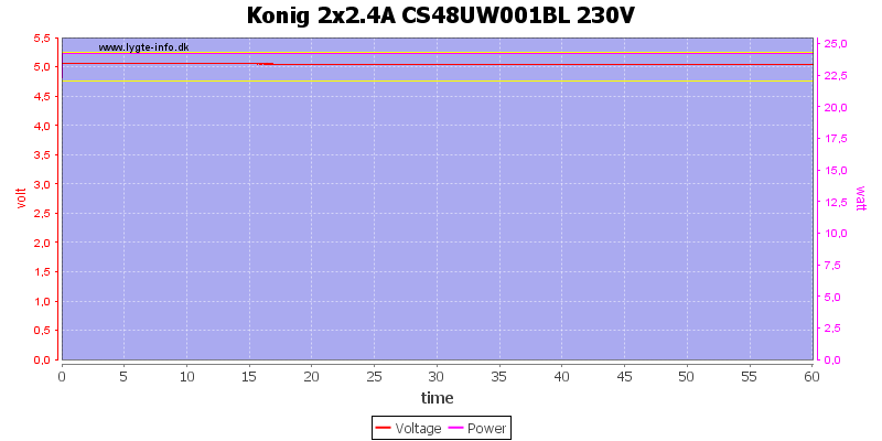
One hour at 4.8A works fine.
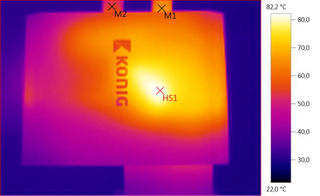
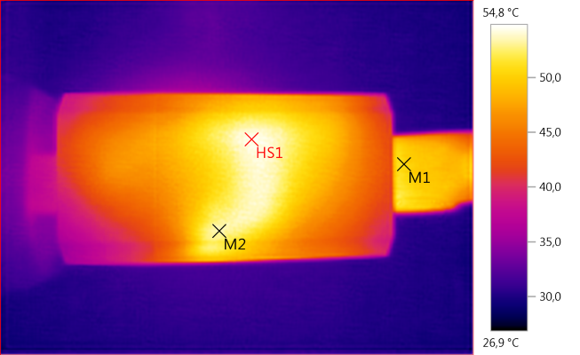
The temperature photos below are taken between 30 minutes and 60 minutes into the one hour test.
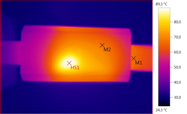
M1: 66,7°C, M2: 67,4°C, HS1: 89,3°C
HS1 is from the rectifier diode and it looks like the position matches some white glue.
M1: 66,6°C, M2: 54,8°C, HS1: 82,2°C
HS1 is the transformer.
M1: 50,7°C, M2: 53,2°C, HS1: 54,8°C
The shape of the warm area matches the mains switch transistors heatsink.
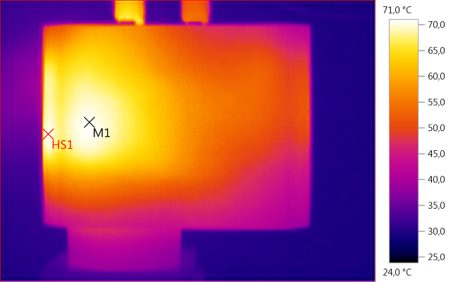
M1: 70,5°C, HS1: 71,0°C
HS1 is below the mains switcher heatsink.
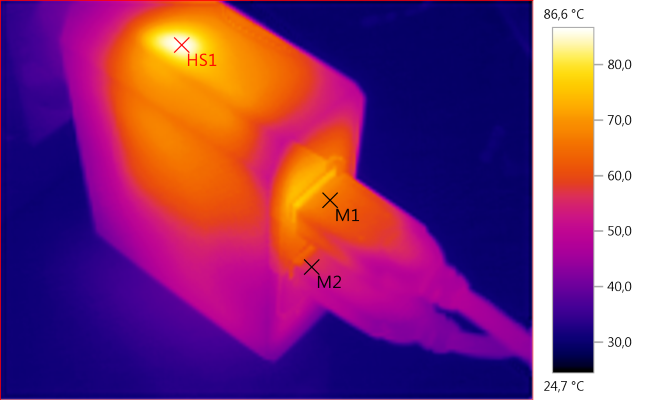
M1: 65,8°C, M2: 56,0°C, HS1: 86,6°C
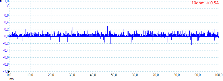
Noise at 0.5A load is: 29mV rms and 807mVpp, the peak noise is rather high.
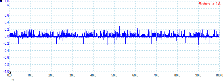
Noise at 1A load is: 41mV rms and 794mVpp.
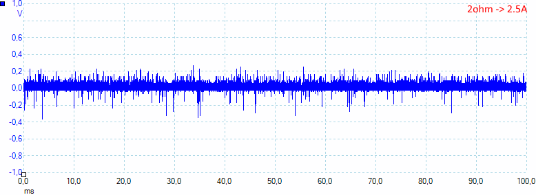
Noise at 2.5A load is: 57mV rms and 944mVpp.
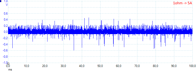
Noise at 5A load is: 75mV rms and 1377mVpp.
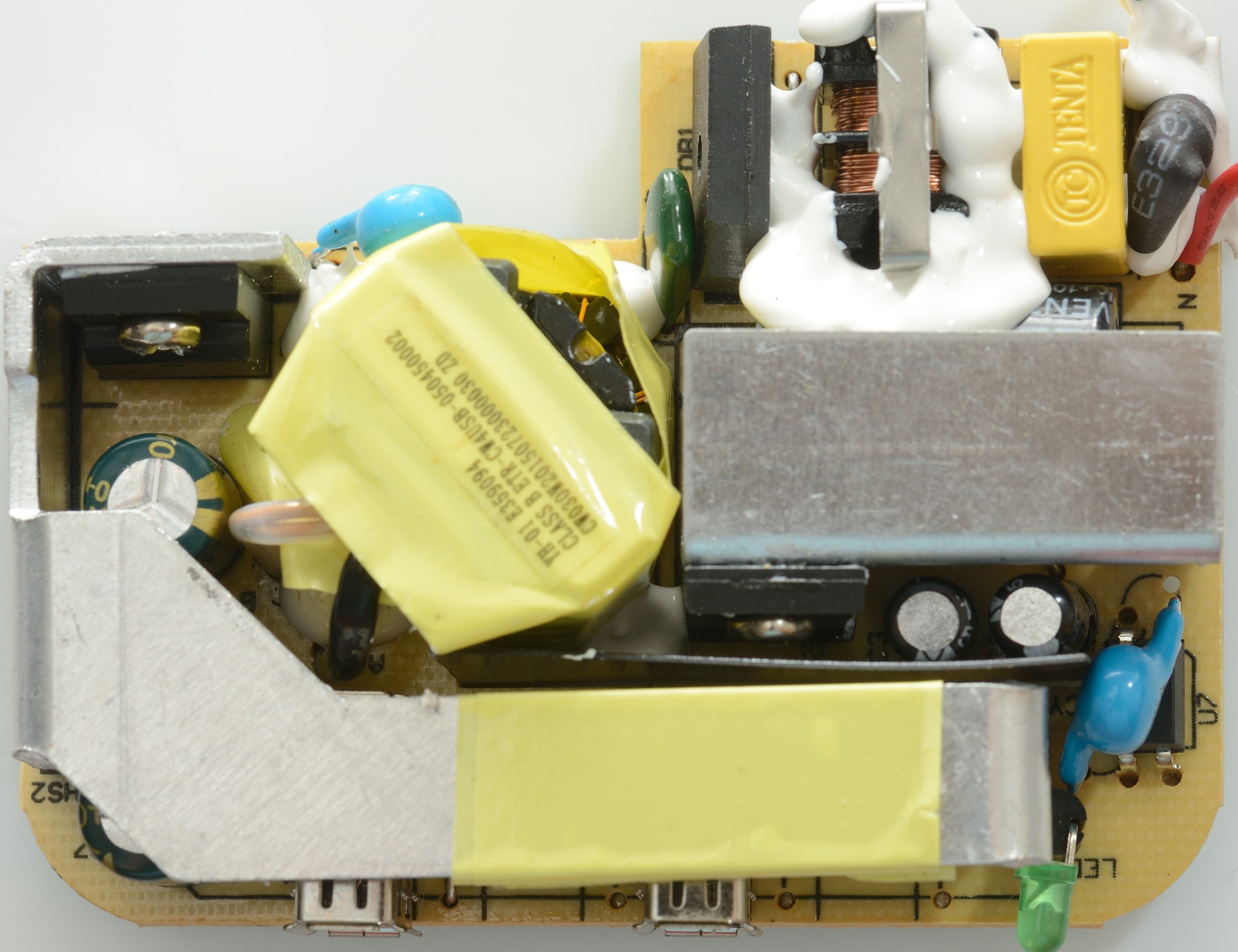
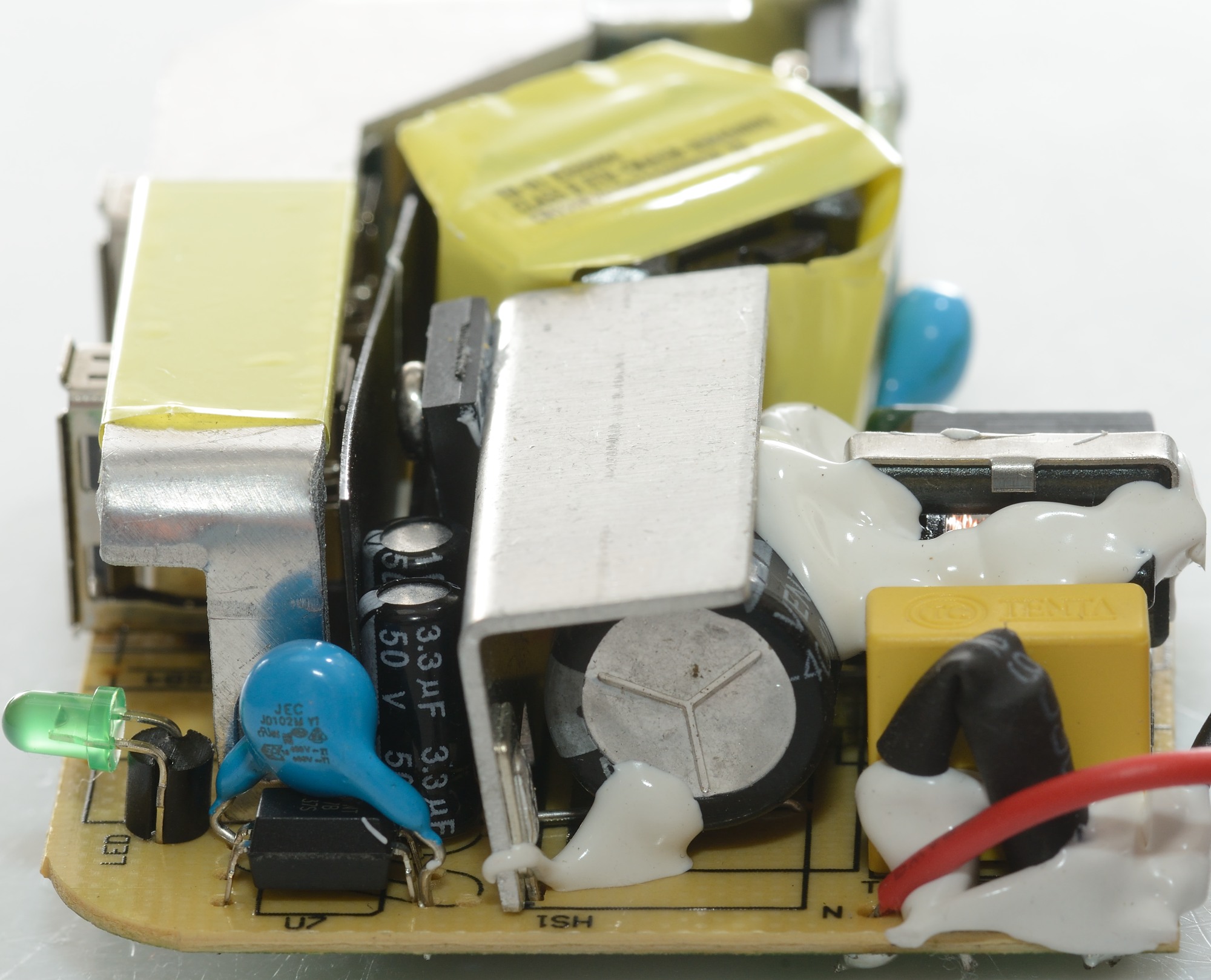
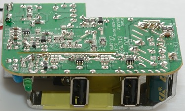
Tear down
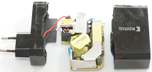
The charger looked easy to open: tie the bottom part in my vice and give the top part a few whacks with my mallet. It worked as expected.

At the mains input is a fuse (Inside black heat shrink), capacitor, a common mode coil and a bridge rectifier. The mains switcher is placed on the heatsink besides the common mode coil. There are two safety capacitors, one besides the transformer and one on top of the opto coupler (U7).
The rectifier diode is mounted on the long heatsink.
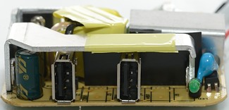
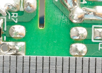
From this side the two usb connectors can be see and space for two usb connectors more. At the right side is the led, opto coupler and a safety capacitor. The black behind the usb connectors is some plastic isolation piece.
The heatsink is also used to carry current from one side of the circuit board to the other.
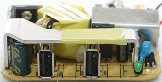
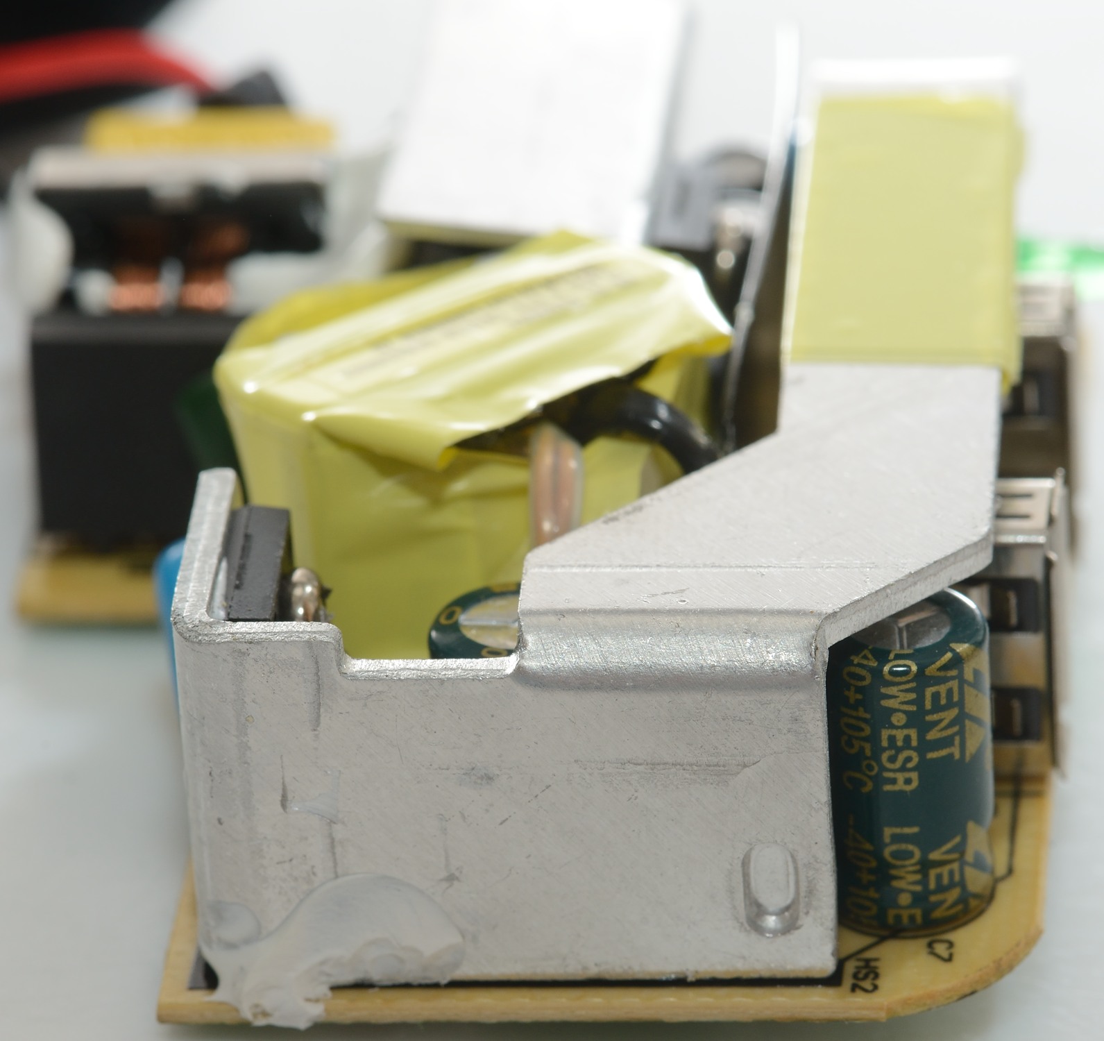
Here I have removed the isolation piece.
From this side there is not much to see, except the rectifier diode heatsink.
There is some white glue on the heatsink and I believe this is transferring heat to the box and making the hot spot in the first IR picture.

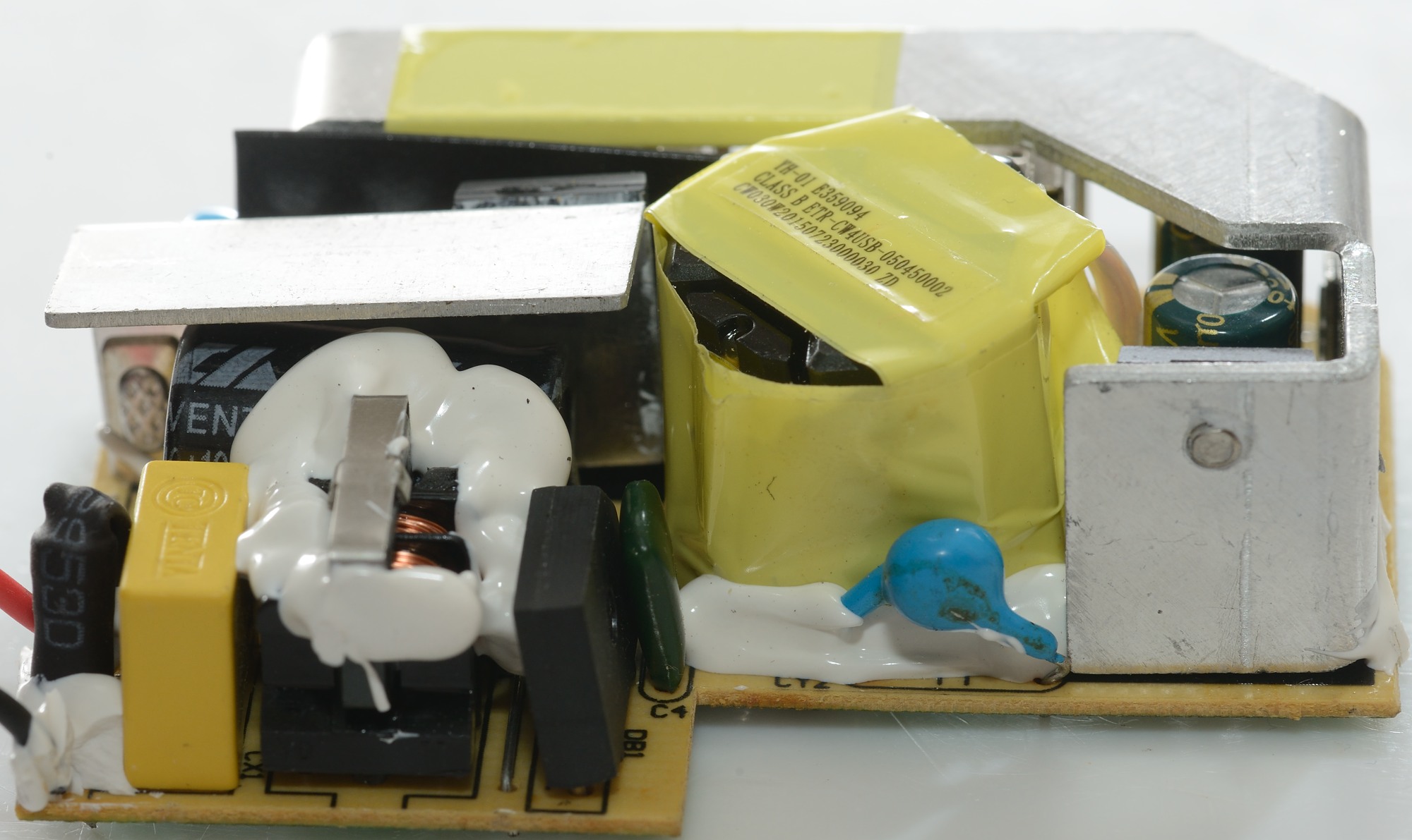
A closer look at the fuse, common mode coil, bridge rectifier and a safety capacitor.

Here the green led, the opto coupler and a safety capacitor. The fuse is behind the red wire.

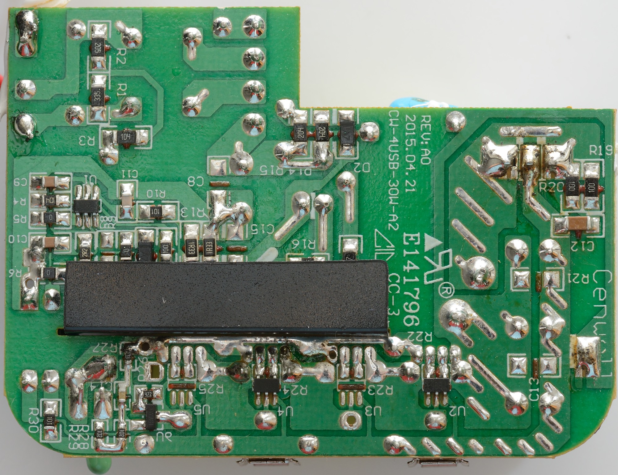
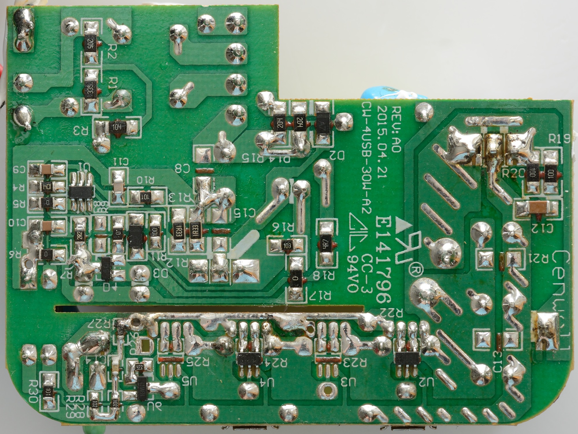
On the bottom is the mains switcher controller (U1 marked: 30F7), the reference (U6 431AEH), two auto coding chips (U2 & U4 marked: E98BJ)

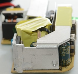
There was a few parts under the black piece.
It looks like there is good isolation distance.
The slot is filled with the plastic piece and there is a very long distance around that.
Testing with 2830 volt and 4242 volt between mains and low volt side, did not show any safety problems.
Conclusion
The charger can supply the rated current without problems, has auto coding and is safe, was it not for all the noise it would be a good charger.
Notes
Charger was supplied by Pro backup (probackup.nl)
Index of all tested USB power supplies/chargers
Read more about how I test USB power supplies/charger
How does a usb charger work?